Abstract: In modern industrial scenario the important role of machine tool and manufacture is very essential for improving each and every commercial expectation seem promote to improve output of the products and which is straight impact regarding the product cost. In our project report concentrating to recognize the performance improvement of the vertical turning lathe (VTL) machine tool through enhancing the cutting speed to improve production rate with fine surface finish. Design, feasibility of manufacturing, time with cost effective have also considered in this work. Furthermore, the precautions as well as sufficient measures have been regards simultaneously. The design software’s such as auto-CAD along with pro-e are used to draw the components design.
Keywords: vertical turning lathe; Design; production rate; surface finish; Auto-CAD; Pro-E
I. INTRODUCTION
In the circumstances of machine tool turning lathe is most general one for the function of metal cutting. In the process of turning, the job is rotating about its axis. The single point material removal tool would be fed on the job to shear away the excess material presents in the job to obtain the desired component. By using turning process, the external as well as internal surfaces could be machined to obtain contoured shape in an axially symmetrical part. The component range from pocket watch to grater diameter of the marine propeller shaft could be turned through Lathe machine propeller shaft. With two dimensions we could be expressed the full capability of the Lathe regarding the maximum diameter of the part, swing as well as maximum length between centers. Commonly, the general use of engine lathe machine is the majority among the basic turning machine tool. The two basic constraints for turning operations are holding the work while rotating and holding the cutting tool furthermore moving them towards Job to be machined.
VTL is a kind of lathe in which the chuck is placed symmetric to y-axis (i.e.) vertically. And generally it does not have tail stock like general purpose lathe machine.
Revised Manuscript Received on May 22, 2019.
Rajaravi C, Department of Mechanical Engineering, VEL TECH MULTITECH, Avadi, Chennai, Tamilnadu, India
Palani S, Department of Mechanical Engineering, VEL TECH MULTITECH, Avadi, Chennai, Tamilnadu, India
Yogesh P, Veltech Engineering College, Chennai-68, Tamilnadu, India
Suresh K, Department of Mechanical Engineering, VEL TECH MULTITECH, Avadi, Chennai, Tamilnadu, India
Selvam M, Department of Mechanical Engineering, VEL TECH MULTITECH, Avadi, Chennai, Tamilnadu, India
By using vertical lathe machine, the performance could be made as like engine lathe machine including make internal as well as external threads, plain as well as taper, step turning, facing and boring. The characteristic features of the vertical turning lathe are a horizontal table or faceplate that holds the work and rotates about a vertical axis; a side head that can be fed either horizontally or vertically; and a turning slide, mounted on a cross rail that can feed no rotating tools either vertically or horizontally.
Sharma et al (2013) found that when implementing one of the outstanding manufacturing quality improvement tool called Statistical process control, the quality of the products eventually obtain better customer satisfaction [1]. Wanare et al (2013) stated that the process capability tool has capable for combination with equipment for producing good quality products so as to meet all design necessities as well as expectation of the customers. Also, they ensure that all the process parameters are well match with manufacturing specifications with allowable process variation. [2]. Archenti et al (2011) discussed about the combination of framework to control the capability of the system of machining [3]. Rajvanch et al (2012) stated that for improving quality continuously, enhancing productivity and make effective managerial decision the indices of the process capability become useful very much. [4]. Shreehah et al (2010) used the capability indices to evaluate the output of the controlled process within the measurement limit as per the decision making [5].
Kahraman et al (2012) found that the process capability index has the numerical summary which comparing product performance and the characteristics of the process with the specifications [6]. Mottonen et al (2008) analyzed the opportunity to reduce the cost of breakdown regarding processes of products for electronics through regulating the cost of electronic production processes by regulate acceptable limits by simulation stages [7]. Gadalla et al (2016) found that the development of manufacturing method in reconfigurable manner with different efforts for reaching Among various efforts to develop reconfigurable manufacturing system, the new advancement in the area of research towards machine tool reconfiguration in both the sector of industrial manufacturing as well as academic technical institutions [8]. Padayachee et al (2012) stated that consideration of design of architecture in reconfigurable manufacturing tool, in order to change the machining platform configuration, the modular type of architecture as well as its various functions
could be preferred [9].
Design Development and Performance
Improvement of Heavy Duty Vertical Turning
Lathe Machine Tool
Koren et al (2013) found that the architecture of reconfigurable manufacturing tools was taken into account for the development of modules for extending the functions in to extend manufacturing functions [10].
Yin et al ((2012) analyzed that the number of computer tools were developed to support the reconfigurable machine tools design process [11]. Goyal et al (2012) found that the different optimization techniques as well as tools were developed to identify the best reconfigurable manufacturing tools [12]. The process cost of reconfiguration by using operational period, production unit cost as well as maximum number of operators involved[13] [14]. Chang et al found that normally visual information have two different kinds one is static for general as well as prompt and another one is dynamic for guiding with make instruction [15]
The main goal of our work is to increase the product output. For which the turning section manufacturing floor is selected. The vertical turning lathe machine is analyzed for increasing its performance. The different parameters such as designing, feasibility for manufacturing, cost effectiveness with desired timing are consider in this research work.
II. VERTICAL TURNING LATHE
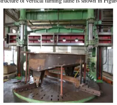
[image:2.595.68.270.351.533.2]The structure of vertical turning lathe is shown in Figure 1.
Fig. 1 structure of vertical turning lathe
By analyzing all the parameters and factors, it is clear that apart from feed rate and material type the chuck speed (rpm) plays a very important role in production timing. Feed rate is not negotiable as it plays a great impact on surface finish and tool life. Whereas compromising the material type leads to poor quality.
Thus by increasing chuck speed (in rpm) we could increase production output which meets our goal. The speed of the chuck has been analyzed based on the various methods for increasing the speed.
Methods of increasing
The RPM of the chuck can be increased by the following methods by changing the motor speed to higher values and by changing the pulley diameters.
Motor
Motor is the primary power producing element in a lathe machine. The mechanical energy produced from a motor is
transmitted through various power transmitting elements to the machine chuck for its rotation. Thus altering its speed will lead to change in chuck speed.
Pulley
The pulley means wheel that located on the axle which be designed for supporting rotation as well as alteration of direction of rope or belt alongside of its perimeter. The pulleys are employing for lifting the loads, applying forces along with power transmission and many ways. A “block” is referred to as gathering the axle as well as wheel along with its shell support in the contexts of nautical. It has groove in between the circumference of the flanges. The pulley is operated with any one of the drive element like chain, cable, rope as well as belt with proper meshing. Generally, for manufacturing, the lathe and the other machines are connected with puller by means of motor. It consists of power sources and transmission structure. A machine consists of a power source and a power transmission structure, which offered power with control of application. The transmission structure is called drive train which consists of clutch with gearbox and connected with propeller shaft to differential and shafts of the final drives.
III. METHOD OF CHANGING MOTOR SPEED
Motor Specifications
H.P = 42; VOLTS = 250; R.P.M = 580
Gear box specifications
HP = 53; Input speed= 590; Output speed = 28.3; from the given specifications it would be wise for us to choose motor of 720 rpm to increase the chuck speed.
Method by changing pulley diameter
Driver Pulley = 510MM Driven Pulley = 400MM
d1 n1= d2 n2 Where, d1 is the diameter of the driving pulley
n1 is the revolutions of the driving pulley d2 is the diameter of the driven pulley n2 is the driven pulley revolution. n2 = d1 n1 /d2
From the above relations we can conclude that by increasing driving pulley diameter, decreasing driven pulley diameter revolutions of driven pulley can be increased which in turn increases chuck speed.
Selection of the most appropriate method
By changing motor it is also must to change the gear box for suitable input R.P.M. The cost estimated for replacing the motor is about 10 lakhs of Indian currency. The speed increase can be achieved by either increasing driver pulley diameter or decreasing driven pulley by applying both greater results are produced.The cost estimated for changing the pulley diameters is about 80,000 of Indian currency.
Method by changing pulley diameter
Let us consider the pulley diameter to be increased to a certain value so that the
r.p.m to 12 rpm which is twice the current value.Thus it is aimed for increasing the chuck speed to a value of 100% so that maximum product output can be obtained.
IV. DESIGN CALCULATION
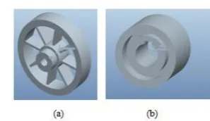
The design and other key factors of the pulleys are improved by theoretical method. The improvements are made for obtaining 100% increase in chuck speed which is 12 r.p.m. The drive (a) and driven (b) pulley are shown in Figure 2.
Fig. 2 (a) Drive pulley (b) Driven pulley
The design calculations are made as per specifications Driver pulley = 510 mm
Driven pulley = 400 mm Motor speed= 580 RPM
Revolution of Driven Pulley
Revolution of driven pulley =(diameter of driver pulley × revolution of driver pulley) /diameter of driven pulley
n2 = d1 n1 / d2 = (510*580)/400
n2 = 739.5
The current chuck bed speed is 6 RPM, where we are aiming to achieve twice the speed of 12 RPM.
Thus the revolution of driven pulley must also be twice which is 1479 RPM (N2)
To avoid failures and moment the driver pulley diameter must be always smaller than the motor’s armature for safe working conditions. The armature diameter is 720MM.Thus it is safer to consider the driver pulley as 700MM (D1) Where,
D1 is diameter of the driven to be designed; N1 is revolutions of driving pulley
D2 is driven pulley diameter to be designed; N2 = driven pulley revolutions
Diameter of Driven Pulley
Diameter of driven pulley=(Diameter of driving pulley revolutions of driving pulley)÷ revolutions of driven pulley
D2 = D1 N1 / N2
Where, D1= 700 MM; N1= 580 RPM; N2= 1479 RPM; D2 = (700*580)/1479;
= 274.5 MM
Thus let us conclude that Diameter of Driven Pulley as 275 MM.
Concluded values
D1 = driving pulley diameter to be designed = 700 mm N1 = revolutions of driving pulley = 580 rpm
D2 = driven pulley diameter to be designed = 275 mm N2 = revolutions of driven pulley = 1479 rpm
Some other values for implementation are,
Centre distance = 1200 mm; Connecting belt length = 3831 mm; Number of belts planned to be implemented is 8; the type of belt is planned as v-belt
Cad Designing
From the calculated values of driving and driven pulleyCAD models of both driving and driven pulleys are done, so that the design can be analyzed and improved for implementation.
[image:3.595.63.274.218.349.2]CAD model of driving pulley in pro-e
Fig. 3 CAD model of (a) Driver (b) Driven pulley
The numbers of spokes are chosen as 8 so that the design is well balanced in structure. The small pulley is manufactured with simple design and with no complex parts so that the pulley is small as well as balanced. Both the pulleys are given with one key slot for each for the introduction of key for a rigid power transmission so that vibration is avoided.The number of grooves in driven pulley is given as 11 so that the belts can be arranged on different angles for rigidness and slips can be avoided. The material for manufacturing was chosen as cast iron.
[image:3.595.346.495.236.322.2]possible due to reduce friction. The bearings are generally classified based on the operational type as well as direction of motion with method applying parts load.
A rolling element of bearings capable to carry the load through its rollers and balls contains with rings or casing. The virtual moment of pieces around the bearing elements is the reason for roll by way of extremely minimum resistance while performing as rolling as well as sliding. In order to make by way of minimum resistance of rolling among minimum sliding to make this system more rigid a projection in pulley design is introduced, so that the bearing can be placed over it.
The projection is given with a diameter of 180mm.Thus the bearing to be selected must have an inner diameter of 180mm for the respected I.D preferred bearing is 6036M with the following specifications.
Inner Diameter is 180 mm, outer diameter is 280 mm and the width or height or thickness is 46mm.
[image:4.595.326.528.252.408.2]The bearing is just an machine element for relative motion. It is needed to be fixed i.e. mounted on a casing so that the required support is obtained. Thus design is carried out for it. The CAD design of bearing casing and check are shown in Figure 4 (a) and (b0 respectively.
Fig. 4 CAD design of (a) Bearing Casing (b) Chuck and its parts
As per the specification of the bearing the interior of the casing is designed for 280mm as diameter and so the thickness. The pulley to the bearing is mounted to the casing on a rigid surface. The shaft is made as a simply supported beam for preventing the motor failure.Whereas no special precautions are made for the driven pulley as it is only reduced in its size and it is not attached to any power producing element. And its structural balance is also maintained by its design.
Precaution measures for chuck elements
As aim of the project is increasing chuck speed, it is the at most concern for checking failure possibility and taking precaution measures for the chuck elements.Apart from the elements that helps chuck from rotating, there are also other elements which is used for lifting the chuck table. These various parts are studied for failure and precaution is produced in this phase.Main chuck elements:Chuck table; Gear tooth below table; Chuck body shaft; Bush and Worm gear.
Comparing any other parts the section where heavy wear and stress shall occur is the section where bush and worm gear connect. The function of worm gear in this assembly is to transmit motion vertical wise.In general the worm gear
meshes with bush at the bottom of chuck shaft and when the worm gear is made to rotate it exerts force on the bush and allows the shaft (i.e.) chuck to move vertically.Due to the increase in the speed of chuck rotation apart from any other parts this section will be under high stress and wear forces.Comparing any other parts the section where heavy wear and stress shall occur is the section where bush and worm gear connect. The function of worm gear in this assembly is to transmit motion vertical wise.
In general the worm gear meshes with bush at the bottom of chuck shaft and when the worm gear is made to rotate it exerts force on the bush and allows the shaftchuck to move vertically.Due to the increase in the speed of chuck rotation apart from any other parts this section will be under high stress and wear forces. The wear section of chuck is shown in Figure 5.
Fig. 5 Wear section of Chuck
[image:4.595.68.267.373.461.2]V. RESULTS AND DISCUSSION
By the results found on design calculations pulleys were manufactured and implemented. The new (a) driver and Driven pulleys and (b) Bearing Case are shown in Figure 6.
Fig. 6 New (a) driver and Driven pulleys (b) Bearing Case
It is implemented with all accurate measures and values as designed. The current improvement is the machine function was noted down.
Old chuck speed: 6 RPM; Newchuck speed: 10 RPM; speed increased: 60%
Thus the aim for increasing the production output by increasing the VTL machine chuck speed is achieved.
Precaution measure for motor
The suggestion for installing the bearing and casing was approved and implied which produces a smooth power transmission and avoid failures in future.Thus the motor life is maintained.
Precaution measures for chuck elements
The precaution measures for avoiding chuck elements failure were proposed and accepted. Whereas it was said to be implied in the near future so that continuous production in current project of the organization can be achieved.
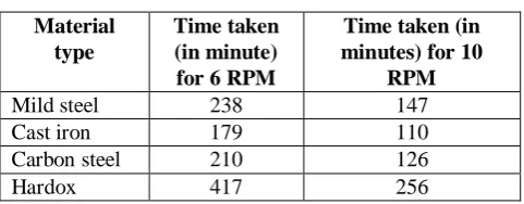
Feed rate: 0.5 mm/min; Job diameter: 4 m
[image:5.595.62.276.132.248.2]The machining times for different RPM are tabulated in Table 1.
Table. 1 Machining time for different RPM
Material type
Time taken (in minute) for 6 RPM
Time taken (in minutes) for 10
RPM
Mild steel 238 147
Cast iron 179 110
Carbon steel 210 126
Hardox 417 256
It is clear from the obtained data that the increase in chuck speed as resulted in decrease in production time. Thus the product output is increased.The advantages obtained by this implementation are: decrease in production time, increase in the quality of surface finish, increase in production output and increase in profit.
VI. CONCLUSIONS
This project is intended towards increasing the production output by the speed efficiency of vertical turning lathe machine. Accordingly design alterations were made and proposed for the machine considering different parameters such as possibility for manufacturing, calculation for design, effective prize, as well as constraints of timing. The safety as well as sufficient procedure is besides concurrently researched along with deployed on regard. For designing the parts the required software that Auto-CAD as well as pro-E have been utilized.
REFERENCES
1. Sharma, G.V.S.S. and Rao, P.S. (2013) Process Capability Improvement of an Engine Connecting Rod Machining Process. Journal of Industrial Engineering, 9, 1-9.
http://dx.doi.org/10.1186/2251-712x-9-37
2. Wanare, S.P. and Gudadhe, M.V. (2013) Performance Analysis of Vertical Machining Center through Process Capability, International Journal of Innivations in Engineering and Technology, 2, 198-207 3. Archenti, A. (2011) A Computational Framework for Control of
Machining System Capability. Ph.D. Thesis of KTH Royal Institute of Technology, 97 p. https://www.diva-portal.org/smash/get/diva2:458645 4. Rajvanchi, P.K. and Belokar, R.M. (2012) Improving the Process Capability of a Boring Operation by the Application of Statistical Techniques. International Journal of Scientific & Engineering Research, 3, 1-6. www.ijser.org/viewPaperDetail.aspx?I014630 5. Shreehah, T.A.A. (2010) Extending the Technological Capability of
Turning Operation. International Journal of Engineering, Science and Technology, 2, 192-201. www.ijest-ng.com/ijest-ng-vol2-no1-pp192-201http://dx.doi.org/10.4314/ijest.v2i1.59112
6. Kahraman, F., Esme, U., Kulekci, M.K. and Kazancoglu, Y. (2012) Process Capability Analysis in Machining for Quality Improvement in Turning Operations. Material Testing, 54, 120-125. http://dx.doi.org/10.3139/120.110306
7. Mottonen, M., Belt, P., Harkonen, J., Haapasalo, H. and Kess, P. (2008) Manufacturing Process Capability and SpecificationLimits. The Open Industrial and Manufacturing Engineering Journal,1, 29-36. http://dx.doi.org/10.2174/1874152500801010029
8. Gadalla M, Xue D. Recent advances in research on reconfigurable machine tools: A literature review. International Journal of Production Research 2016 (online, doi:10.1080/00207543.2016.1237795). 9. Padayachee J, Bright G, “Modular machine tools: design and barriers
to industrial implementation”, Journal of Manufacturing Systems, 2012; 31(2):92-102.
10. Koren Y, Hu SJ, Gu P, Shpitalni M, “Open-architecture products. CIRP Annals” Manufacturing Technology, 2013; 62(2):719-729.
11. Yin YH, Xie JY, Xu LD, Chen H, “Imaginal thinking-based human-machine design methodology for the configuration of reconfigurable machine tools”, IEEE Transactions on Industrial Informatics, 2012; 8(3):659-668.
12. Goyal KK, Jain PK, Jain M, “Optimal configuration selection for reconfigurable manufacturing system using NSGA II and TOPSIS”, International Journal of Production Research 2012, 50(15):4175-4191. 13. Samy SN, ElMaraghy H, “A model for measuring products assembly
complexity”, International Journal of Computer Integrated Manufacturing, 2010, 23(11):1015-1027.
14. Soh SL, Ong SK, Nee AY, “Design for assembly and disassembly for remanufacturing”, Assembly Automation, 2016, 36(1):12-24
[image:5.595.49.290.561.655.2]