Abstract: Wind turbines used in power generation have to deal with the aspect of reducing flow losses. In that case, the power generation systems are expected to have improved performance. Present work discusses one such experimentation to explore the flow over the cylinders and cylinder with cone. The effect of presence of cylinder on stream lines perpendicular to the fluid flow at cylinder is 4 cm from the center line on both sides. Flow gets deviated from its path and as the area increases. After crossing the cylinder center line, as the area decreases the flow gets accelerated and moves to downstream. When flow encounters the cylinders which are in parallel, similar complex features are observed. Fluid diverges from its path and flows over and re-attachment is found at a distance of 4 cm from both the cylinders. Presence of two cylinders causes two attachment points and two recirculation zones. These re-circulating zones at each cylinder rejoin with the free stream flow. Also, the effect on stream lines is up to 1.5cm from each cylinder towards another cylinder. There is formation of convergent section between them and it compresses the fluid as area is reduced, accelerating the flow up to center line of the cylinders. After that, fluid again gets diverged, reduces its velocity and rejoins with the main flow. Similarly, study is made when the cylinders are in series. Thus, results give more insight to the flow over cylinders, which are in parallel and series that find many applications in real time like wind turbines. The above complex behaviors are reduced to great extent when using the cylinder with cone. And it is observed that the vortex size is reduced. And the presence of this object on stream lines perpendicular to the direction is also reduced.
Index Terms: Flow over multiple cylinders, Flow separation, Recirculation, Boundary Layer.
I. INTRODUCTION
Power generation systems deal with the flow scenario of the working fluid. Flow of the fluid should be without any losses. Working fluid can be either gas or liquid. If any obstacle is present, it leads to flow losses. These losses lead to energy loss in the system under operation. Such losses lead to reduce the power generation efficiency and increase the generation as maintenance costs. In order to reduce these, we should ensure that flow is smooth and free from instances like separation, attachment, reversal and vortex generation. Wind turbines are the promising technologies in power generation in view of depleting fossil fuels. The primary application of
Revised Manuscript Received on June 05, 2019
K. Ashokachary, Asst. Professor, Dept. of ME, VJIT, Hyderabad, India. Contact No: +91-63026 08018
Dr. Chirra Kesava Reddy, Principal, Dept. of ME, SRTIST, Nalgonda J. Pradeep Kumar, Asst. Professor, Dept. of ME, VJIT, Hyderabad, India. V. Rajarao, Asst. Professor, Dept. of ME, JITS, Narsampet, Warangal Ravi Kumar Kotturi, Asst. Professor, Dept. of ME, VJIT, Hyderabad, India
wind turbines is to generate energy using the wind. Aerodynamics is a very significant aspect of wind turbines. Formation of wakes, the regions of disturbed flow downstream of a solid body moving through a fluid, caused by the flow of the fluid around the body. Wake regions contain lot of flow turbulence, leading to the formation of vortex regions. This will reduce the power generation capabilities of the wind turbine. Reduction of wake formation is possible only if we study it experimentally. Flow over cylinders is deals with this scenario. Flow in case of wind turbines has to deal with many aspects like flow separation and attachment, vortices and wakes as shown in Fig.1 [1]. It is very important to reduce flow separation and study when exactly vortex is generated. Vortex generators improve the performance of the blades by energizing the flow around its surface and reducing flow separation. The performance of the entire turbine in terms of power, load and service life has to be improved. Only, few researchers have studied about flow in wind turbines. The force generated because of wind interaction with the turbine blade is the basic motive of the wind turbine. Wang et al. [2] studied the fluid structure interaction causing aero elastic effects with increasing size of large wind turbine blades. Maximum stresses and tip deflections were found to be within the material and structural limits. Whale et al. [3] investigated the properties of vortex wake behind the wind turbine rotor at different operating conditions. They observed the fundamental behavior of the helical vortex with insensitive to blade chord Reynolds number. Pourrajabian et al. [4] studied a methodology to design fast-starting blade with more power output and allowable blade stress. A hollow blade expedited the starting at low speeds by decreasing the blade inertia, while the resultant stress along the blade not exceeding the allowable stress. Chalothorn et al. [5] used software package to design a 300 kW, variable speed horizontal axis wind turbine with various operating conditions to get maximum energy. It was found that at low wind speed around 10 m/s turbine achieved 50.5% efficiency at the design wind speed ratio of 7.5. Subbarao and Govardhan [6] applied staggering of the second rotor blade and varied speed ratio in order to ensure reduced flow losses in a turbine that has two rotors rotating in the opposite direction. This may positively affect the performance of the gas turbine stage. This means that flow losses occur when the flow passes over the turbine blade, where the working
fluid can be either gas or wind. It is clear that more turbine power output can be
Visualization of Flow Pattern over Cylinders and
Cylinder with Cone for Improved Performance
of Wind Turbines
achieved by designing the wind blade in such a way that the blade should have minimum flow separation with reduced vortex formation. In this context, our present study finds significance, where flow over cylinders in various configurations is studied. It will allow us to see the aspect of increasing the power output from the wind turbine, if we can reduce flow separation and related losses.
II. FLOW OVER CYLINDERS
Fluid particles change their direction, while flowing over the cylinder. These diverging fluid particles increase their pressure and reduce kinetic energy, so that near to the cylinder, the fluid particles move very slowly. After they cross the center line of the cylinder, pressure energy is converted into kinetic energy. After the center line of cylinder, the fluid particles get accelerated and rush to the downstream. This accelerated flow from both sides of the cylinder come close to each other and attach again, far away from the cylinder. After they get reattach, the fluid particles find the adverse pressure hill in the downstream direction. Also, they can find the low-pressure region past the cylinder. As they cannot overcome the adverse pressure hill, the fluid particles move back towards low pressure side slowly while attaching to the cylinder wall. Since it is a low-pressure region and because of the presence of unfavorable pressure differences, the back-flow fluid rotates and forms a re-circulated zone. This re-circulated flow regions mix with the free stream flow. The presence of the fluid viscosity slows down the fluid particles very close to the solid surface and forms a boundary layer. The fluid particle motion in low pressure region that is at the back side of the cylinder, creates circular eddies and vortices. Earlier, researchers have studied about flow over cylinders in various ways. But, experimentation towards various instances of cylinders is different. Earlier, Bansal, et al. [7] studied flow through a cluster consisting of three equally spaced circular cylinders. The spacing ratio between the cylinders was P/D=1 .3 5 and the operating Reynolds number was 2 .1×1 0 3 . Experiments were performed using flow visualization. For all cluster orientations, the results show large scale wake vortex shedding about five-cylinder diameters downstream of the cluster. Ong et al. [8] conducted 2-D numerical simulations are performed to investigate free surface waves past two semi-submerged horizontal circular cylinders in tandem. Validation studies of a numerical wave tank have been performed by comparing the numerical simulations with free-surface waves past a partially-submerged horizontal cylinder with the published experimental data under regular wave and deep-water conditions. Zhao et al. [9] also studied two-dimensional flow past two tandem square cylinders with varying incident angles of the downstream one is numerically investigated using an in-house code named the CIP-ZJU model. The spacing ratio (L/D, L is the streamwise center to center space between two cylinders and D is the square side length) of two cylinders is set at different values of 2, 3, 4, 5, 6 and 7. It was found that there exist two kinds of flow modes with different spacing ratios and incident angles. Particularly at L/D=4, there is a saltation phenomenon of the flow mode when the angle changes from 20° to 25°, which has not been studied before. Raiola et al. [10] described the near wake of
two identical circular cylinders in cross flow arranged in tandem configuration in the stream wise direction and with the additional interference of the ground. For a wall-to-cylinder gap equal to 1 diameter, the ground strongly influences the flow field, introducing asymmetry in the typical Von Kármán wake. The ground boundary layer is thickened past the downstream cylinder and a wall-jet appears, enclosed between the wall boundary layer and the cylinders wake. Eventually these flow structures are not distinguishable when the cylinders wake and the wall boundary layer are grown enough to merge. From POD analysis, vorticity blobs appear on the wall, paired with vortex shedding. Pang et al. [11] described the flow pattern around two circular cylinders in side-by-side arrangement with pitch ratios of 1.1 to 7 at a high Reynolds number (Re) of 6×10⁴. A new scheme was proposed to distinguish the wide wake and narrow wake by judging the velocity direction of a specific point in the flow gap. During the investigation of biased flow, an intermediate frequency between the frequencies of narrow and wide wakes was approached to that of a single cylinder. Islam et al. [12] studied two-dimensional numerical approach for flow past a square cylinder in the presence of flat plate, both at upstream and downstream positions for gaps of 0.5 and 1 with the range of Re numbers from 80 to 200. They compared with the flow pattern around a single square cylinder. It was observed that upstream flat plate plays vital role in significant drag reduction. On the other hand, rate of suppression of vortex shedding was high for downstream flat plate case at low Re numbers. To provide more detailed look, present work discusses one such experimentation to explore flow over cylinders. Flow behavior is studied for different cylinder configurations, while arranging them in either series or parallel.
III. RESUSTS AND DISCUSSIONS
A. Flow over single cylinder
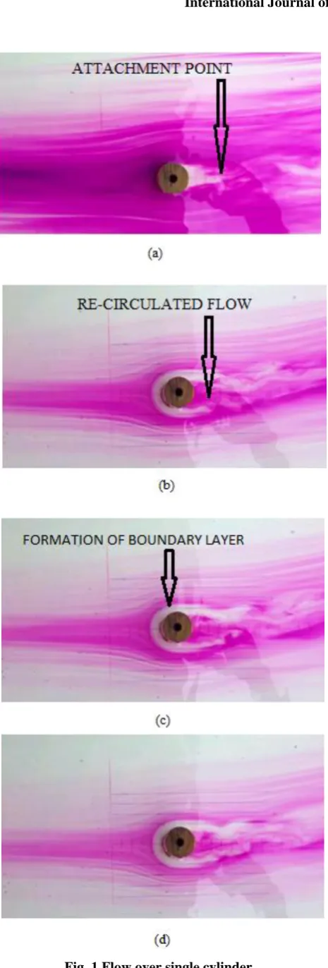
Fig. 1 represents the flow over single cylinder, when flow encounters the cylinder as obstacle in its direction. Then it gets many complex features like separation, attachment, reverse flow, vortex and formation of boundary layer. Initially, the fluid particle comes in contact with the cylinder. Then it diverges from its path over cylinder and it attaches at a distance of 4 cm from the cylinder. Because of the presence of low pressure at the cylinder back side, the attached flow comes back to the cylinder, this creates eddies, resulting in the formation of the recirculation zone.
Fig. 1 Flow over single cylinder
[image:3.595.217.522.75.696.2]B. Flow over single cylinder with cone
Fig. 2 represents the flow over a cylinder with cone shaped object. The blunt shape of object is facing the flow and cone shape (tip) is in the direction of flow (in the downstream). As the flow moves over this object flow separates at a place where cylinder is attached to cone i.e. almost at the center line
of the object. And after separation flow is not coming back unlike in the case of cylinders. This is because of tip, this tip breaks recirculated flow, hence there is a no chance of getting recirculated flow.
Fig. 2 Flow over single cylinder with cone
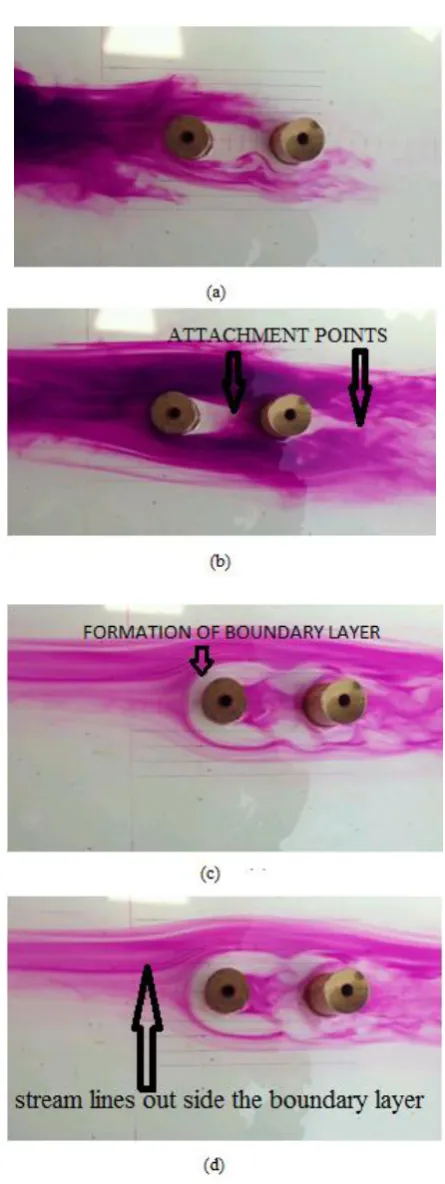
[image:3.595.319.533.240.694.2]Flow over twin cylinders when they are arranged in parallel is shown in Fig. 3. In this case, the flow encounters the two cylinders, which are arranged in parallel to each other in the direction of flow. The flow gets many complex features as we observed in the case single cylinder. In this case, the flow gets obstructed by two cylinders which are parallel to each other and separated by a distance of 4cm apart. Then the fluid diverges from its path and flows over the two cylinders and it attaches at a distance of 4cm from both cylinders. The presence of two cylinders causes two attachment points in the downstream. At the same time due to low pressure at each cylinder, eddies are created, resulting in the formation of two re-circulation zones. These re-circulating zones at each cylinder re-join with the free stream flow and go to downstream. As the time passes, we observe the formation of boundary layers near each cylinder. It is observed that these boundary layers have a thickness of 1 cm to each cylinder. The effect of presence of two cylinders on the streamlines perpendicular to the flow of fluid at the cylinder is about 4 cm from center line of the left cylinder towards left as well as the center line of the right cylinder towards right side of the flow as shown in Fig. 3.
[image:4.595.313.541.50.393.2]In between the two cylinders, the effect on stream lines is up to 1.5 cm from each cylinder towards another cylinder. We observe that there is formation of convergent section between the two cylinders, and it compresses the fluid between them. Because of reduction of area flow is accelerated between the cylinders up to the center line of the cylinders. After that, again fluid gets diverge and reduces its velocity and rejoins with the free stream flow and go to downstream as shown in Fig. 3.
Fig. 3 Flow over twin cylinders when they are arranged in parallel
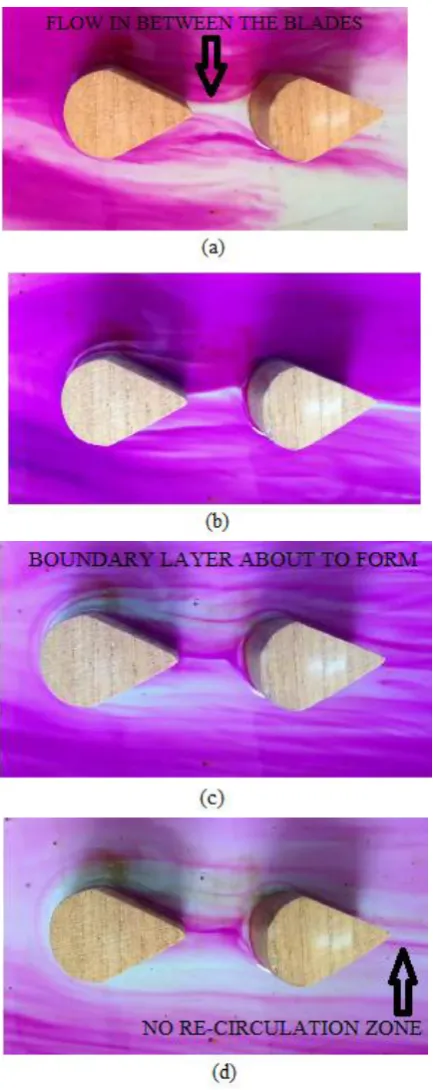
D. Flow over twin Cones when they are arranged in parallel
[image:4.595.60.278.429.727.2]Fig 4 Flow over twin cylinders with cone when they are arranged in parallel
E. Flow over twin cylinders, which are arranged in series
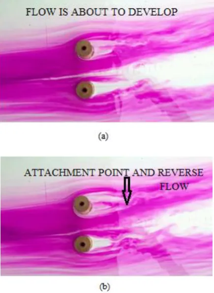
The flow over twin cylinders, which are arranged in series, is as shown Fig. 5. In this case, the flow encounters the cylinders, which are abstracting the fluid in its direction of flow. Here, flow gets obstructed by two cylinders that have same dimensions and separated by a distance of 4 cm parallel to the direction of flow. The presence of two cylinders, which are arranged in series, makes the flow diverges over the first cylinder and attaches at the second cylinder, then the flow diverges at second cylinder and attaches at 4 cm from the second cylinder in the downstream. Due to low pressures at each cylinder, the flow moves back in negative direction and creates eddies, resulting in the formation of recirculation zones at both cylinders, resulting in the formation of vortex at both cylinders as shown in the Fig. 5.
[image:5.595.54.285.48.490.2]As the time passes, we observe the formation of boundary layers near to each cylinder as shown.
Fig 5 Flow over twin cylinders when they are arranged in series
It is observed that these boundary layers have a thickness of 1 cm. The effect of presence of two cylinders on streamlines perpendicular to the direction of flow is about 4 cm from the center line of two cylinders and this effect can see on both sides of the cylinders. In between the cylinders the fluid particles generate strong wake structure as shown in fig (c). When cylinders are placed in parallel arrangement reverse flow with weak vortex can be
But multi cylinders with series arrangement produce strong wake structure and this can be minimized by increasing the distance between the cylinders.
F. Flow over twin cones when they are arranged in series
[image:6.595.66.283.232.778.2]Fig. 6 represents the flow over two objects in series. Initially the flow comes in contact with the one object and after passing over the first one, the flow moves to the second object. The flow between the objects is not recirculated because of the first object tip. where as in case of two cylinders, when they are arranged in series it can be observed that there is a strong vertex in between the cylinders. This vertex can be eliminated by using these objects as shown in figure.
Fig. 6 Flow over twin cylinders with cone when they are
arranged in series.
IV. CONCLUSION
In this work, flow physics over cylinders and cylinder with cones are studied, which is useful in increasing the performance of wind turbines. The effect of presence of cylinder and cylinder with cone on stream lines perpendicular to the fluid flow is analyzed. When flow encounters these models which are in parallel, similar complex features (same as that of single cylinder) are observed. But, presence of multi-cylinders causes more attachment points and more recirculation zones. The boundary layer thickness is affected, if the distance between the models is reduced. By placing the models in series, the vortex zones are reduced and boundary layer size is also changed. Flow separation is not changed, as only one cylinder is facing the flow as in case of single cylinder. But, in the case of parallel arrangement of cylinders, the flow separation is changed because of the presence of more cylinders in the direction of flow. Flow separation occurs on each cylinder and forms more than one boundary layer. When using two models of cylinder with cone cross section in series connection the flow is fully upgraded due to formation of less vortex between the models. When models are placed in parallel to the flow direction the improved flow can be observed as these models are eliminating the vortex in the downward direction, this is because of presence of tip of the cone in down stream of flow which eliminates the recirculated flow. By studying the flow scenario better and thereby reducing the flow losses, we can move towards improved performance of wind turbines. This ensures better utilization of resources available, thus making them more sustainable. Present work gives more insight to the flow physics of fluid passing over cylinders, which finds many real-time applications in energy systems
REFERENCES
1. J. Whale, C.G. Anderson, R. Bareiss, S Wagner, “ An experimental and numerical study of the vortex structure in the wake of a wind turbine”. Journal of Wind Engineering and Industrial Aerodynamics, vol. 84(1), 2000, pp. 1-21.
2. A. Pourrajabian, P. A. N. Afshar, M. Ahmadizadeh, D. Wood, Aero structural design and optimization of a small wind turbine blade”,Renewable Energy, vol. 87(2), 2016, pp. 837-848.
3. L. Wang, R. Quant, A. Kolios, “Fluid structure interaction modeling of horizontal-axis wind turbine blades based on CFD and FEA”, Journal of Wind Engineering and Industrial Aerodynamics, vol.158, 2016, pp. 11- 25.
4. C. Thumthae, “Optimum blade profiles for a variable-speed wind turbine in Low Wind Area”, Energy Procedia, vol.75, 2015, pp. 651- 657. R.Subbarao and M.Govardhan, “Computational Studies on the effect of speed ratio and stagger angle in a counter rotating turbine with respect to flow field and performance”, Fluid Mechanics and Fluid Power – Contemporary Research, 2016, pp. 933-944.
M.S. Bansal, S. Yarusevych, “Experimental study of flow through a cluster of three equally spaced cylinders of local pressure drop for turbulent flow in axi-symmetric sudden expansions with chamfered edge”, Experimental Thermal and Fluid Science, vol. 80, 2017, pp. 203-217.
X. Zhao, D. Cheng, D. Zhang, Z. Hu, “Numerical study of low-Reynolds-number flow past two tandem square cylinders with varying incident angles of the downstream one using a CIP-based model”, Ocean Engineering, vol. 15, 2016, pp. 414–421. M. Raiola, A. Ianiro, S. Siscetti, “Wake of tandem cylinders near a wall”, Experimental Thermal and Fluid Science, vol. 78, 2016, pp. 354- 369. 6. J.H. Pang, Z. Zong, L. Zou, Z. Wang, “Numerical simulation of the flow around two side-by-side circular cylinders by IVCBC vortex method”,vol. 119, 2016, pp. 86-100.