Abstract— The proposed work is about vehicle crash evasion framework utilizing an ultrasonic sensor for a vehicle. We utilize the use of electronic frameworks implanted in a car which is required to limit the vehicle mishap fiasco. The RFID (Radio Frequency Identification) methods focus on building up a model of the backside and other significant vehicle crash shirking framework that will recognize the separation between two vehicles moving in a similar path, in a similar bearing and alarm the driver at whatever point the person is in threat range utilizing a microcontroller. The separation is estimated by an ultrasonic sensor used to detect the snag ahead.
I. INTRODUCTION
A fender bender is an occurrence during which a car either leaves from standard pathway into a dump, or crashes into whatever makes harm the vehicle, including different autos, utility poles, structures, and trees. Here and there an auto crash may likewise allude to a vehicle striking a human or creature. Auto collisions additionally called streetcar crashes (RTAs), car accidents, car crashes, street mishaps, individual damage impacts, engine vehicle mishaps, and accidents impacts more on the human life in the most worst manner based on the statistics generated by WHO. About 90% mishaps are due to the driver carelessness which gets increased in the most recent days due to lack of governing sectors in the transportation sectors. Department of Transport distributes street passing acknowledgement for every vehicles crossing screening area located at appropriate stations. Main insights are accessible by "Danger of damage estimated by the level of drivers harmed in two-vehicle damage mishap". The evaluated insights demonstrate a 20 to 30 proportion of in-vehicle mishap passing between protected and analyzed simulation models of vehicle. Various books have basically investigated the obligation of vehicle creators for security. Auto crashes fall into a few noteworthy classifications, for example, Main-head impacts, Side-end vehicle crashes and Level intersection mishaps which can happen with different cars, different vehicles, for example, bikes or trucks, with people on foot or enormous creatures, and with stationary structures or items, for example, trees. In an impact between two vehicles, the inhabitants of a vehicle with the lower mass will probably endure the more noteworthy outcomes. This undertaking goes for building up a viable apparatus for improving the operational effectiveness and use of vehicles. The uses of RFID have demonstrated progressively invaluable in
Revised Manuscript Received on September 10, 2019.
P.Parameswari, Department of MCA, Kumaraguru College of Technology, Coimbatore, Tamilnadu, India.
E.B.Priyanka, Department of Mechatronics Engineering, Kongu Engineering College, Perundurai, Tamilnadu, India.
everyday life which can give high-precise correspondence of information between the tag and peruser. This task investigates a specialized point of view and talks about the benefits and bad marks in impact cautioning framework.
II. EXISTING AND BACKGROUND WORK BASED ON RFID
Radio Frequency Identification (RFID) is a programmed ID strategy, depending on putting away and remotely recovering information utilizing gadgets called RFID labels or transponders. An RFID tag is an article that can be appended to or consolidated into an item, creature, or individual with the end goal of recognizable proof utilizing radio waves. Chip-based RFID labels contain silicon chips and receiving wires. Uninvolved labels require no inner power source, though dynamic labels require a power source.
2.1 History Of Rfid Tags
In 1945, the Soviet government developed and experimented episode radio waves incorporated with sound data. In the world-war II, the propagation of sound wave are used for their secret communication with the model development of transponder. The innovation comes with the stage of resonator with channel for frequency range fixing and modulating the phase with quad core ranging. The reflection and resonance principle replaced the electromagnetic field combination with inductor and capacitor for efficient data range communication.Stockman anticipated by proclaiming "extensive innovative work must be done before the staying fundamental issues in the reflected-control correspondence are fathomed, and before the field of helpful applications is investigated."
2.2 Types Of Rfid Tags
RFID cards are mainly classified as "vicinity" or "intermediary" cards. It includes three main categories: detached, semi-inactive (otherwise called semi-dynamic), or dynamic.
2.2.1 Passive Tags
Latent RFID holds no internal built power supply. The CMOS coordinated chip transmit the momentum based electrical current flow through the wires to propagate the signal transmission by tuning proper modulation techniques. It relies mainly on the backscatter data transmission to initiate the frequency allocation. The easily erasable programmable RAM is used to make reliable process in the automobiles with easy temporary memory storage buffer.
Collision Warning System using Rfid in
Automotives
The ID number will be supported with bar code to access the specified memory location address with proper program code.
The expansion of the radio wire makes a label differing fromminimum dump card to the on-board single chip transient controller. Uninvolved labels have down to earth perused separations running from around 12 cm (6 in.) Commercial contingent upon the picked radio recurrence and receiving wire configuration/size is fixed with the standard of ISO 4390 Er25.
2.2.2 Semi Passive Tag
Semi-aloof RFID labels are fundamentally the same as inactive labels with the exception of the expansion by little battery. The in-built batter enables label IC for continuous controlling to evacuates the requirement by aeronautical intended to gather control by various advanced approaching sign. Aerials be further enhanced by supporting with backscattering signal. Semi-detached RFID labels are along these lines quicker accordingly, however less solid and ground-breaking than dynamic labels. Semi-latent labels offer advantages in situations by great deal of metal or liquids which disperse the RF field.When semi-latent labels are coding oriented-point stimulated, consumers constancy gets increased all the more dependably and progressively troublesome conditions.
2.2.3 Active Tag
Dynamic RFID labels holds miniaturized power booster utilized to control any microprocessor that develop the active sign. Dynamic labels are normally considerably much dependable (for example less mistakes) than uninvolved labels to lead a "session" with a per-user. Dynamic labelstransmit at higher power levels than prescribed frequency spectrum, enabling progressively compelling on "RF tested" situations. Numerous dynamic labels were down to earth scopes of many meters mainly due to their battery life of as long as 9 years.
Some dynamic RFID labels incorporate transmitters, for example, real-world data logging mainly been utilized for solid development checking or to identify specific characterization of transient products. Different transmitterswere hitched with dynamic RFID incorporate mugginess, stun and physical quantity identification. Dynamic labels possess longer range (roughly 5 km) and bigger recollections than detached labels by its capacity to stockpile extra data transmitted by the handset.
III. THE RFID SYSTEM
An RFID frame structure comprises of several segments: labels, label perusers, edge servers, middleware, and application programming. The motivation behind an RFID framework is to boost up the data communication in the short range with better multiplexing and modulation techniques. The proper tags will be allocated for well-tuned identification with bar code or labelling with specified frequency bands. The utilization of RFID in following and access applications previously showed up in 1932, to distinguish flying machine as cordial or hostile ("recognize companion or adversary" (IFF). RFID immediately the moving mobility rate is monitored to compare with the receiving tag field correlation. On the upgradation of refined technology, progressively unavoidable and potentially intrusive usesof RFID labels are incorporated for well enactment.
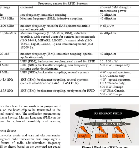
Table 1. Frequency ranges used for RFID systems
The per-user deciphers the information as programmed decoded data on the board-chip to be transmitted to the master terminal control unit. The application programming regularly utilizing Physical Markup Language (PML) on the main firmware for enhanced sensibility and warning notification.
3.1. Frequency Ranges
RFID frameworks create and transmit electromagnetic waves as designated radio frameworks band range signals. The main feature of radio administrations frequency allocation will be altered based on the generated tag coded signal rates of RFID functioning frequency. It is especially imperative byassuring that RFID frameworks don't meddle with close-by radio and TV, versatile radio administrations (police, security administrations, and industry), and cell phones. The main extensive care relies on the radio administrations altogether confines the scope of appropriate working frequencies accessible to a confined RFID framework. Hence, it is generally just conceivable to utilize recurrence runs that have been held explicitly for mechanical, logical or restorative applications situated on the low frequency band areas. The frequencies characterized standard normsby ISM (Industrial-Scientific-Medical) to be followed based on the utilization band range areas with proper specifications.
[image:3.595.53.552.70.379.2]3.2. Working Of Rfid
Figure.1 Working of RFID system
3.2.1. Modulation
Occasional vacillations in the plentifulness of the bearer used to transmit information again from the tag to the peruser. Frameworks consolidating inactive RFID labels work in manners that may appear to be strange to any individual who as of now gets RF or microwave frameworks as appeared in Figure 1. There is just a single transmitter – the detached tag isn't a transmitter or receiver in the most perfect meaning of bidirectional correspondence communication. The RF field produced by the decoder tag has three purposes:
3.2.2. Generation of power in the coupling coil to boost up the coil:
peruser field. 327 kHz and 32.58 MHz label plans must work over a huge unique scope of bearer contribution, from the extremely close field (in the scope of 200 VPP) to the most extreme read separation (in the scope of 5 VPP).
3.2.3. Powered with clock source in synchronizes source manner
Numerous RFID labels separate the bearer recurrence down to create a finite model machine operated by proper timing triggering pulse from the clock, counters, and so on and to determine the information came back to the peruser on the basis of transmission bit rate speed. A few labels, notwithstanding, utilize locally available oscillators for clock age.
3.2.4. Back data propagation through carrier tag
The back data propagation is established by implementing back scatter modulation technique. The reader tag produces radio frequency waves and the modulated signal is transmitted to the receiving tag. The receiving tag converts the data to the energizing field based on the energy module propagation with the emitter tag. The signals are stored in the processor for controlling and sequencing programming in the radio coil.
IV. IMPLEMENTATION IN AUTOMOBILES FOR COLLISION WARNING SYSTEM METHODOLOGY
4.1.Concept of distance measurement
Atransponder holding inductive coupling contains an electronic information conveying gadget, more often than not anon-board microchip incorporated with zone loop that capacities as a radio wire as appeared in Figure 2. Inductively coupled transponders are quite often worked inactively. This implies all the vitality required for the activity of the microchip must be given by the peruser. For this reason, the peruser's receiving wire loop creates a solid, high recurrence electro-attractive magnetism passes into the coil windings to energize the cross wiring sensor system. Since frequency band associated with data transmissioncapability (< 142 kHz: 3200 m, 17.21 MHz: 34.21 m) plays major role between the radio wire coupling windings and the fixed transponder, the electro-attractive field serves as the straightforward attractive exchanging field as for the separation among transponder and receiving wire. A minimum power rating of produced field infiltrates
the reception apparatus curl and boost up the voltage in the auxiliary loop for sensing the transponder. By enlistment, a voltage (VI) is created on the radio wire coils due to the transponder interaction. This voltage is corrected and fills in as the main actuator for the information conveying gadget (board-chip). A capacitor is associated with the peruser's receiving wire loop in parallel combination, the capacitance of discharged rate gets mapped with the inductance of the coil by the generated electro-magnetic field around the radio wire. High flows are produced by receiving wire loop on peruser due to reverberation venture above the thunderous circuit, further utilized to create the necessary field qualities for the functioning of the positioned transponder as appeared in Figure 3.
The radio wire terminal section is operating with the magnetic induction principle to transmit the detected signal from the proximity sensor and alert the driving person. The capacitor is cross coupled to reduce the excess current passage to the relay circuit through radio wire transmission. The initial voltage is maximized and it gets coupled and transformed to higher end through secondary winding of the step up transformer. The wires gets cross connected to send the alert signal to the emergency warning system in the chassis of the automobile. The auxiliary layer perform other functions like communicating data to the Engine Management system about the detection ratio rate for better perception. The voltage rise at certain point is controlled by the realy and the capacitor coupling. The capacitor discharges excessive current which is consumed by the battery for charging purpose with the happening rate of 0.76 seconds.
On the off chance that a full transponder (for example the self-resounding recurrence of the transponder relates with the transmission recurrence of the peruser control utilization estimates the occurrences of voltage drop in the peruser receiving wires to the peruser's radio wireat the interior obstruction by supply current). This is set with in the attractive rotating field of the peruser's reception apparatus, and after that this draws vitality from the attractive field. This extra turning on and off of a heap opposition at the transponder's receiving wire along these lines impacts voltage changes at the peruser's radio wire and in this manner remote transponder stabilizes the voltage drop by receiving the proper switching control signal from the main terminal.
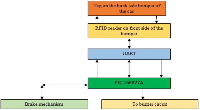
Figure 3. Block diagram of collision warning system
Figure 4. Percentage of death toll vs types of collision without warning system.
Figure 5. Percentage of death toll vs cause of death without warning system
[image:5.595.114.485.595.730.2]Figure.7 Percentage of death toll vs cause of death with warning system
V. RESULT AND DISCUSSION
Among various collisions analyzed in Figure 4-7, the rear end collision and head on collision have most impact on the lives of the people .The death toll is higher at the rear end collision in order to save the precious lives there need a safety system .
The result analysis describe that there is a death toll of 33% due to vehicle collision for each and every year. The insights shows that for mainstream, gently assembled autos, tenants have a 6–8% possibility of death in a two-fender bender. Customary "security autos, for example, the Higher end cars like Mini cooper reduces the death rate due to advanced opportunity given with collision detection with the 8% reduction by 76 Mini cooper model and Lamborghini by 12%. The BMW and Skoda are most preferred model which satisfies with BS IV norms incorporated with rear end warning system to motivate to reduce road crash by 36%. In any case, in different vehicle crashes SUVs are very little more deadly than traveler autos. In spite of the fact that, rollovers are considerably more typical in SUVs when contrasted with traveler vehicles due to their top weight. Thus SUVs really present a more prominent risk on rollover and cause a casualty as opposed to traveler vehicles. Motorcyclist passing inside England and Wales remain at 53% of the yearly street demise measurements. Bikes with higher engine capacityaround 200cc where undergone several injury rate of 12% with crashing over heavy duty vehicles with the crashing rate of 5% to 20%. These undertaken survey related to street passing vehicle collision analysis. The vehicles with 50cc duty vehicles are undergone only minor rate of injury collision due to the lack of following Compulsory Driving Norms (CDN).
These statistics enables us to implement a safety system which safeguards the people from the crash to death.It is predicted that in this research prospects will have major role in reducing the impact caused by various collision. Particularly rear end collision and head on collision are approximately reduced to a value by 60%to 80%.
The graph in Figure 7 represents percentage of death toll versus the types of collision with the warning system. It confrims that there will be a reduction of 40 to 50 percentage of death toll with increase in safety using the warning system in automotive. We predicted that collision warning system designed here will provide an automatic braking more effectively and efficiently. Two vehicles with
the relative speed of 300 km/hr can be controlled effectively without the collision. Since, the entire monitoring and execution process is completed within 300microseconds for each and every routine. This enables us to provide safety with accuracy.
VI. CONCLUSION
RFID based vehicle warning system promises to bring radical improvements over many other systems that have an impact on the lives of everyone. By combining RFID with PIC controller, the identification with warning is more effective. Intelligent system with RFID will enable car and the truck users to avoid collision and find more efficient way of driving towards the destination. This project focuses primarily low cost RFID sensors, PIC controller for any integrated movement warning tasks.
VII. REFERENCES
1. James K. Kuchar and Ann C. Drumm, 2007, The Traffic
Alert and Collision Avoidance System, VOLUME 16,
NUMBER 2, 2007 LINCOLN LABORATORY
JOURNAL.
2. Cheng-Neng Hwang, Joe-Ming Yang and Chung-Yen
Chiang, 2001, The design of fuzzy collision-avoidance expert system implemented by h∞- autopilot, Journal of Marine Science and Technology, Vol. 9, No. 1, pp. 25-37 (2001)
3. “Safety Analysis of Proposed Changes to TCAS RA Reversal Logic,” RTCA DO298, Washington, D.C., 8 Nov. 2005.
4. J. Kuchar, “Update on the Analysis of ACAS
Performance on Global Hawk,” Aeronautical
Surveillance Panel, International Civil Aviation Organization (ICAO), SCRSP WG A/WP A10-04, Montreal, 1–5 May 2006.
5. Nagaraj Balakrishnan, Reshmi S., and R. Arunkumar. "Smart real time rescue system for fishermen." Pak J Biotechnol 15, no. 1 (2018): 73-75.