SUPPORTING “DESIGN FOR REUSE” WITH MODULAR DESIGN
JS Meehan, AHB Duffy, RI Whitfield
CAD Centre, James Weir Building, University of Strathclyde, Glasgow, G1 1XJ, United
Kingdom
Correspondence to: RI Whitfield, CAD Centre, James Weir Building, University of Strathclyde, Glasgow, G1 1XJ, United Kingdom.
Telephone: +44 (0) 141 548 3020
Fax: +44 (0) 141 552 3148
1 Abstract
Engineering design reuse refers to the utilisation of any knowledge gained from the design activity to support future design. As such, engineering design reuse approaches are concerned with the support, exploration and enhancement of design knowledge prior, during and after a design activity. Modular design is a product structuring principle whereby products are developed with distinct modules for rapid product development, efficient upgrades, and possible reuse (of the physical modules). The benefits of modular design centre on a greater capacity for structuring component parts to better manage the relation between market requirements and the designed product. This paper explores the capabilities of modular design principles to provide improved support for the engineering design reuse concept. The correlations between modular design and ‘reuse’ are highlighted, with the aim of identifying its potential to aid the little-supported process of ‘design-for-reuse’. In fulfilment of this objective we not only identify the requirements of ‘design-for-reuse’, but also propose how modular design principles can be extended to support ‘design for reuse’.
2 Introduction
‘Design-for-reuse’, whereby current artefacts are designed with a specific emphasis on promoting, extracting and enhancing re-usable knowledge elements, has been shown in previous studies to have the most significant impact on the realisation of ‘reuse’ related benefits [1]. Interestingly however, research by the author [2] [3] has shown that, of all the reuse processes, ‘design for reuse’ suffers from a most notable lack of support. Thus, the potential for various principles to support ‘design for reuse’ was investigated as part of a project to develop a method to improve support for formal design reuse. This lead to the identification of modular design as a candidate for modelling and structuring design knowledge for ‘reuse’.
Modular design is a natural extension of structuring principles. It involves the creation of artefact variants based on the configuration of a defined set of modules. Modules are commonly described as a group of ‘functionally’ or ‘structurally’ independent components clustered such that ‘interactions are localized within each module and interactions between modules are minimised’ [4]. The principle aims to create variety, reduce complexity and maximise kinship in designs and across product families. Due to the fact that individual module functions and/or structures must eventually combine to realise the overall function/structure of the artefact, the modules can never truly be independent and must be defined together with the system to which they belong. Thus, further ‘between module’ or ‘interface’ constraints must be considered for modules to be successfully configured to meet overall system requirements. Modular design research can generally be grouped into 3 categories: the identification of modules; the design of modules, and designing with modules. The approach outlined within this paper predominantly considers issues related to the first two categories. However, the later is encompassed when the output of the tool is further utilised from a ‘design by reuse’ perspective.
2.1 The relation between modular and reuse principles
In exploration of why modular design so readily maps to the ‘reuse’ perspective we consider some of the major benefits of the modular approach [5] [6] [7] [8] [9] [10] [11] [12], these include:
• Efficient upgrades because it ‘bounds change into smaller areas of product development’ and thus upgrades of the overall functionality of a design can be achieved without completely redoing the design’.
• Improved design understanding due to the need to understand how and why individual elements interact in the overall system. Thus, modular design enhances learning at the component level and increases understanding through the drive to capture solution-based design knowledge, past experiences, and documentation of working procedures.
• Improved knowledge structures as the principle reinforces the need for better structuring and handling of tasks and knowledge. Here, modular architecture provides a knowledge map of where to store new knowledge and access previous knowledge.
• Improved knowledge management as the modular architecture can promote a systematic approach to knowledge management and can aid the definition of a model for managing information flow and knowledge in product development.
• Improved knowledge utilisation whereby through reuse of defined modules, well-known knowledge is consequently utilised relating to savings in time and money.
• Rapid product development facilitated by the ability to rapidly reconfigure existing modules and introduce new modules. Further, modular design can be utilised to support fast adaptation in developing markets.
• Reduction in costs due to the rapid development opportunities afforded by modular designs, where costs and lead times are cut, and business efficiency improves through the reuse of design and manufacturing processes.
These benefits centre on a greater capacity for structuring both physical parts and artefact knowledge to better manage the relation between market requirements and the design artefact. Hence, they support increased utilisation of experiential knowledge for new product development and thus provide an approach on which to actively support reuse.
However, despite the existing evidence as to its benefits, ‘little work has been done on these research issues’ [5]. In 1995, Chang and Ward [10] noted that ‘none of the design theories or tools in the mechanical world serves as an articulate procedure for designers to follow in practicing modular design.’ Despite continued developments in the field of modular design, further inadequacies were highlighted by Miller and Elgard [13], and Huang and Kusiak [14]. The later stating that ‘modularity has been treated in the literature in an abstract form’ and ‘approaches are needed to determine modules, represent modularity, optimise modular design and assess the impact of modularity on the design process, manufacturing and management’.
2.2 Modular design supporting ‘design for reuse’
There is a current drive towards modular structuring of products, motivated by the large body of evidence as to its benefits. However, the phenomenon still suffers from a lack of definition and understanding. As for reuse, currently no modular design methodology specifically emphasises support for ‘design for reuse’.
To support ‘design for reuse’ it is hypothesised that a modular design methodology/tool would be required to:
• Support the dynamic knowledge generated by the designer by:
o Supporting the different viewpoint requirements of the designer throughout the product
development process.
o Support design knowledge as it proceeds from the abstract to the concrete.
o Support mapping between viewpoints to increase trace-ability and understanding of the
impact of design decisions.
o Capture generated design knowledge in an explicit formalism to support its subsequent
reuse.
• Support the generation of modules based on various viewpoint and/or lifecycle objectives by:
o Providing a mechanism to cluster elements into modules within each viewpoint or
alternatively across a number of viewpoints.
o Allowing the designer to map between each viewpoint to optimise module definition and
design.
o Providing mechanisms to bias clustering to optimise the generated modules with respect
to significant lifecycle objectives.
o Support mapping between viewpoints to facilitate a deeper understanding of the impact
of change in a module and/or of a life cycle objective.
• Support the reuse of generated modules and their associated knowledge by:
o Providing an explicit formalism for design knowledge / module definitions.
o Allowing new design changes/ decisions to be mapped onto a previous module design
process to explore their impact and support partial reuse of design modules.
3 Current
approaches
insufficiency of such current work we must firstly define our understanding of some essential terminology within the context of the proposed methodology.
Viewpoints in Design
Initially, it is important to provide a more concise definition of our understanding of a ‘viewpoint’ within the context of this research. Viewpoints represent structured views of ‘engineering design’ required by the designer to evolve the engineering design process to a suitable conclusion [15]. Previous work by Duffy [16], and Manfaat [17], has concentrated on the notion of a ‘customised viewpoint’ which advocates the abstraction and generalisation of specific design knowledge into appropriate viewpoints according to the designer’s needs as illustrated by Figure 1. For example, designers may generate viewpoints based on their current focus: geometrical, numerical, spatial, functional, mechanical, behavioural, structural.
KEY:
Abstract Concept Relation Between Concepts
Plane Representing A Viewpoint
Designer Imposed Perspective Viewpoint originating from a source
Designer
[image:5.612.148.467.218.495.2]Sources of Design
Figure 1. Customised viewpoint approach in design [16]. Design Life-Cycle Objectives
Secondly, we define a life-cycle objective to be the expression of a required or preferential need with respect to an individual or group of artefact stakeholders from any stage of the entire artefact life-cycle (of which the ‘design process’ can be considered only one phase i.e. customer, designer, manufacturer, assembler, user, maintainer, disposer). The prime concern of this research however is the artefact life-cycle phase of ‘design’, from ‘requirement to definition’, and how best to support this ‘for reuse’.
3.1 Single viewpoint approaches
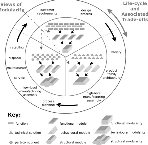
The majority of approaches focus solely on a particular viewpoint, generally a functionally or structurally orientated one. Existing approaches to modularity could be grouped into 3 distinct categories based on: function, the potential means or technical solution of realising this function, and finally on physical parts and/or components as shown in Figure 2.
modules. The realisation of the defined ‘functional’ modules as physical entities is left to the designer. Kusiak and Huang modularise at a functional level to support a deeper investigation of the performance versus cost trade-offs of potential solutions to customer requirements. Thus, functions are selected and clustered into distinct modules with ‘fuzzily’ defined parameters. Such early representation of modularity supports the subsequent decision making process allowing the designers to concurrently investigate design trade-offs at a greater level of detail while maintaining the overall integrity of the design. Ouyang et al utilises ‘functional modularity’ to support a ‘design by reuse’ perspective. Based on a defined set of customer requirements they can select the most similar functional modules from previous cases of machine tool elements. Thus suitable modules are made available for either their direct reuse, or as the basis for the development by the design team. Such cases illustrate, as depicted in Figure 2, that the focus of approaches which embody what we term here as ‘functional modularity’ is on facilitating ‘early’ life cycle objectives i.e. those associated with the matching or mapping of customer requirements.
Chang and Ward [10] provide examples of ‘behavioural modularity’ based on the technical solutions or means of fulfilling the functional criteria of a design. Chang and Ward focus on the minimisation of variation across a product family by reducing the ‘conceptual noise’ of technical solutions with respect to the requirements of components and/or assembly sets i.e. module and/or component sharing philosophy. Erixon’s Modular Function Deployment (MFD) approach [20], looks at modularity across the wider spectrum of the design process, however, the module identification phase focuses on clustering of potential technical solutions (or means) to functional objectives. Here the solutions are analysed and grouped into modules based on their correlation with a number of module drivers. The main emphasis here, as depicted in Figure 2, is on ‘mid-life-cycle’ objectives such as creation of variety, component/module sharing across product families and generations, and high level manufacturing and assembly trade-offs.
Key:
function functional module functional modularity
technical solution behavioural module
part/component structural module
behavioural modularity
structural modularity customer
requirements
variety
high-level manufacturing
assembly product family architecture
low-level manufacturing
assembly process planning service
disposal recycling
design process
Life-cycle and Associated Trade-offs Views of
Modularity
[image:6.612.185.424.378.613.2]maintenance
Figure 2. Modular design views and their impact.
disposal method, recycling capabilities etc. Similarly, Masuda utilises the modular design at a ‘structural level’ to improve the upgrade prospects of products which are technologically driven or have long in-service life spans. Kamrani, utilises this modular approach, in well-developed design domains when technology, materials and design is mature and subject to little flux, with the aim of maximising kinship in terms of manufacturing requirements and assembly operations and thus capitalising on potential process improvements. ‘Structural modularity’ focuses predominantly on later-life cycle objectives i.e. low level ‘nuts and bolts’ assembly, process planning, service, maintenance, parts reuse, recycling and disposal (see Figure 2).
Each ‘view’ of modular design is seen to support a particular ‘stage’ of the ‘design phase’ of the artefact life-cycle, thus, design knowledge generated out-with the considered ‘stage’ is neither explicitly captured, modelled nor utilised by the approach. ‘Design for reuse’, the identification, extraction and enhancement of possible reusable knowledge fragments, requires a systematic approach to the capture and structuring of generated knowledge throughout the engineering design life-phase from its inception. Thus, due to the potential for knowledge of different types, media, scope, and abstraction level, to exist at different levels of completeness we surmise that it is inconceivable to utilise any individual viewpoint as a facilitator of ‘design for reuse’ [3]. For instance, Kamrani [22] expresses concern that ‘conceptual design modules’ those of a ‘functional to technical nature’, cannot meet the constraints of later stages of design. Further, it can be said that due to the nature of ‘structurally’ orientated modules they fail to capture and/or explicitly represent knowledge from earlier conceptual phases of design. Further, each ‘view’ of design is seen to facilitate an exploration and realisation of a particular set of life-cycle objectives pertaining to the designed artefact. However as knowledge external to the taken ‘view’ is not utilised the impact of the trade-off between differing sets of life-cycle objectives cannot be explored. However, we aim to overcome these difficulties and exploit both the structuring and life-cycle objectives exploration capabilities afforded by a modular approach as a mechanism for supporting ‘design for reuse’. Thus, we have identified and aim to address the need to develop a methodology which allows the designer to examine and express modularity throughout the design process to promote a deeper understanding of: the nature and evolution of modularity; life-cycle objectives and modular trade-offs; and to promote systematic extraction and representation of design knowledge from project inception ‘for reuse’.
3.2 Multi-viewpoint
approaches
Although the majority of modular design approaches can be categorised within the views posited in Figure 2, there is increasing recognition of the requirement to support the multiple viewpoints of design within a coherent and integrated structure. Jarventausta and Pulkkinen [24], and Salheih and Kamrani [25], Tseng and Jiao [26] have all attempted to encompass such aspects in their approaches to product platform, product architecture and modular design.
When, Jarventausta and Pulkkinen [24] discuss ‘views’ of a product model, they equate to the requirements of individual stakeholders with respect to the designed artefact. The approach focuses on internal stakeholders, which include: engineering design, manufacturing, marketing, logistics, sales etc. As shown in Figure 3, they treat engineering design as a single ‘viewpoint’ where previously we have illustrated that to facilitate effective ‘design for reuse’ we require to support this ‘engineering design phase’ over the series of ‘viewpoints’ which evolve the design from the abstract to concrete.
Sales View
Manufacturing View
Marketing View
The Engineering Design Activity
As a View of the Product Model
As Customised Views
Sources of Design
The Product Model
An Attached View
Data structured within view to represent stakeholders requirements /objectives.
[image:8.612.95.530.78.370.2]KEY:
Figure 3. Views of the product model [24] and customised views [16].
Salheih and Kamrani[25] note that the principle of modularity ‘can be applied in product design, design problems, production systems, or all three’, thus acknowledging the need to support different views of the artefact design. Their four-step methodology covers the design process from need to concept with the aim of determining the modularity in design concepts and utilising these modules as the basis for the allocation of development teams. The detailed design of such modules is left to the development teams. Further, due to the need for decomposition of the design concept, the focus of their approach is predominantly towards cases of redesign and/or where the design and problem domain are well developed, documented and understood. Thus, they observe modularity only at the ‘macro level’ where the granularity of design problem and process is at a relatively low level i.e. basic needs, requirements and component types. The product’s modularity is only explored in one step (step 4: concept integration) and through one view (a low level structural view). The previous steps being utilised as data gatherers to support this analysis. Despite an acknowledgement of the need to support different ‘views’ of modularity in design and their additional prescription of necessary design activities for earlier design, they do not explore nor attain modularity and its associated benefits until late in the design process. Thus the approach fails to adequately support the artefact evolution and thus support and maintain design knowledge for reuse.
views are independent and issues relating to different business functions are dealt with in different views and mapping between the viewpoints is utilised to maintain the product family when initiating new product design. Thus, the approach aims at exploring the underlying modularity of the various technologies applied to already existing products and their customer base.
The three approaches all support product modularity from ‘design-by-reuse’ perspective. They are all applied to cases of redesign or cases that do not ‘include novel engineering design tasks, but systematic variant design’ [24]. All require access to a significant number of past cases, and require that there is an abundance of customer and marketing information available on the product. For example Tseng and Jiao’s approach is applied to the field of industrial products, due to: the availability of large repositories of product knowledge; an abundance of historical data; the ease of accurately classifying market needs; the knowledgeable customers, the limited customer base; and the incremental as opposed to innovative nature of development. The above approaches attempt to explicate the underlying modularity of an existing set of past cases for utilisation to support new design. Each acknowledges that there can be multiple ‘views’ of the artefact knowledge. The tendency is however to consider ‘engineering design as a single ‘view’ with others representing additional phases in the lifecycle of the artefact and/or life-phase objectives/requirements. The author’s proposed approach focuses solely on views of the ‘design process’ with the intention of furthering the understanding of relation and constraints within and across viewpoints of the design process to aid the realisation of modularity from project inception. By developing methods to define and manage modularity from the higher level ‘functional’ requirements to ‘lower level’ parts, geometry and physical characteristics, we aim to take into account life-phase modular needs during design whilst utilising the principle as a tool to extract, manage and enhance design knowledge ‘for reuse’.
3.3 Issues in modular design support for reuse
A number of issues have been raised through research into existing modular design methodologies. These include issues of knowledge management, relation definition and the incorporation of life-cycle objectives during design. The following illustrates why their resolution is of particular importance to successfully support modular design for reuse.
3.3.1 Knowledge modules
In addition to the definition of the physical module, Miller and Elgard [Miller and Elgard, 1998] recognise the need to capture related ‘knowledge modules’ and abstractions of these. They express a need to explore the concept of modularity in relation to ‘knowledge management and modules seen as knowledge carriers’.
Such exploration is essential to facilitate a ‘design for reuse’ modular methodology as it is well documented that previous solutions are rarely wholly re-usable [29], [30] & [3]. Without adequate provision for the knowledge related to how and why the final solution was derived, it is difficult to effectively facilitate the ‘reuse’ of partial solutions. Thus, as current approaches do not adequately formalise, nor maintain, the knowledge behind defined modules they are consequently too inflexible to fully support ‘design for reuse’.
3.3.2 Relations
constraints. Some approaches attempt to overcome such problems by assigning weighted measures or similarity functions to relations, however, none fully support the dynamic dependency characteristics in terms of type, strength, importance, direction, and transformations based on viewpoints and module drivers. Thus, it is suggested that a deeper understanding and more adequate support of: within and between module relations, and across viewpoint relations would aid in the management of such difficulties.
3.3.3 Lifecycle objectives
Life-cycle objectives such as recycling, maintenance, assembly, and disposal are the focus of a number of modular design approaches [21], [31]. For instance, Gu et al focus on the grouping of components with similar life spans or material compositions for recycling or disposal. Different sets of lifecycle objectives are the distinct consideration of particular ‘views’ of modular design (as illustrated in Figure 2). Thus, out-with the boundaries of that particular ‘view’ the designer has, no formal mechanisms to further explore the implications of these chosen objectives and resulting trade-offs exist as the artefact definition evolves. However, a multiple viewpoint approach would allow for a ‘deeper’ understanding of how a life cycle objective related to, for instance, ‘functional’ performance impacts on, say, the ‘structural’ components and vice versa. Thus, any trade-offs between objectives can be explored from design inception.
The above properties of modularity require further research. The need for research in these areas has been noted in [13], [21], [31] and [23]. Thus, where the benefits of modular design suggest a potential to support the process of ‘design for reuse’, the problems lie in our current understanding of what and how to support design knowledge, to meet the needs of the designer in creating and maintaining modules and their associated knowledge for ‘reuse’.
4 A modular design methodology for reuse
A novel ‘multi-viewpoint modular design methodology’ has been developed that aims to address the previously outlined issues and inadequacies of modular design support. The methodology consists of four main elements: a knowledge formalism, an interdependency matrix application, a clustering mechanism and a mapping mechanism.
4.1 Modular design methodology components
The methodology has been developed to support the exploration and maintenance of a modular design by modelling viewpoints and perspectives of design knowledge, optimising these models, identifying their inherent hierarchical modular structure and then mapping between these viewpoints.
4.1.1 The knowledge formalism
Means View Function
View
Solution View
Parts View
Multi-views of Current Working Knowledge (CWK)
[image:11.612.172.433.73.161.2]Causal-Link Relation
Figure 4. Multi-viewpoints of CWK in design [32].
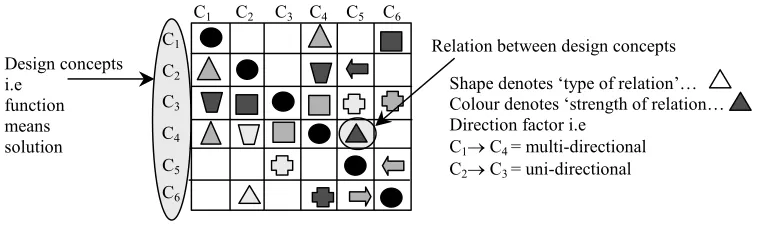
The approach allows the designer to formalise knowledge within viewpoints as concepts (encapsulating knowledge of the designer’s ideas of the design) with attributes (input matters, output matters, behaviour properties, principle properties, parts, etc.) and constraints (both on the concept and attributes - Figure 5a and relations between concepts - Figure 5b). Concept constraints indicate application conditions whilst attribute constraints represent dependencies between individual attributes. Between concept relations can have a type (Has-kind, A-kind-of, A-part-of, Has-part, Functional-dependency, Physical link) and a direction (see Figure 6). Relation constraints consist of pre and post relation constraints. The formalism also notes a causal link relation across viewpoints, Figure 4.
Constraints Constraints
Concept attributes
Concept Concept
Constraints
Relation (type, direction)
(a) (b)
Figure 5. Main elements of CWK [32].
This formalism was utilised since it supports the evolution of a design whilst defining relation/dependency knowledge between concepts both within and across viewpoints of design.
4.1.2 The interdependency matrix application
[image:11.612.139.478.323.456.2]matrix formalism as illustrated in Figure 6. The representation of the formalised design knowledge concepts and their dependencies within a matrix is termed the viewpoint model.
C1 C2 C3 C4 C5 C6
C1
C3
C2
C4
C6
C5
Design concepts i.e
function means solution
Relation between design concepts
Shape denotes ‘type of relation’… Colour denotes ‘strength of relation… Direction factor i.e
C1→ C4 = multi-directional
[image:12.612.114.494.113.228.2]C2→ C3 = uni-directional
Figure 6. An Interdependency Matrix Application.
A viewpoint model is created for the differing viewpoints of interest throughout the design phase, i.e. function, working principle, structure. Within the viewpoint model, the matrix rows and columns represent the same concepts (in the same order) and dependencies within the matrix itself.
4.1.3 The clustering mechanism
Various clustering and grouping techniques are currently under investigation to support the module design and optimisation process. The techniques are required to support module design based on a number of issues, including:
• Maximisation of internal relations between concepts.
• Minimisation of external relations between concepts.
• Concept, attribute and relation constraints.
• Significant lifecycle objectives i.e. manufacturing, maintenance, technology life-spans etc.
• Maximum and minimum module number and size.
A clustering criterion was produced as the first stage of addressing the issues identified above within Equation 1. The equation represents the summation of the dependencies both above and below the leading-diagonal multiplied by the distance from the diagonal on the basis of their weight. The focus of minimising the clustering criterion is therefore to get the most weighted dependencies as close to the diagonal as possible. Thus grouping dependent concepts together with priority automatically given towards those with higher weighted dependencies.
(
)
(
)
∑ ∑
= =−
×
=
Ni N
j
j
i
w
i jCriterion
lustering
1 1 ,
C
1Where N is the number of concepts in the matrix, i and j are the row and column indices, and wi,j are the dependency weights.
Once the clustering criterion has been minimised for a given matrix, the Module Identification Mechanism is used to address the difficulties associated with identifying modules. The Module Identification Mechanism consists of two parts: the Module Strength Indicator (MSI) function and a Module Structure Matrix (MSM).
strength of the internal dependencies is defined as the actual weight of the dependencies divided by the maximum number of dependencies that may exist within a concept grouping. The maximum value of dependencies that may exist within a concept grouping can be defined as the number of potential dependencies between the concepts in the group multiplied by the maximum weight value of the dependencies. The maximum number of dependencies within any concept grouping is the sum of the available row and column intersections, i.e. squares in the matrix excluding the diagonal. Thus, the maximum value of dependencies, of any potential grouping, is the sum of the available row and column intersections within the concept grouping multiplied by 1.0 (the maximum value of a dependency).
Equation 3 determines a mean value for the external dependencies out with the concept grouping. The focus is towards identifying concept clusters that have a maximum number of internal dependencies and a minimum number of external dependencies, i.e. concept groupings of high modular value. Therefore subtracting Equation 3 from 2 can derive the relative modularity of the clustered sequence, with respect to its concepts’ internal and external dependencies. The MSI function, Equation 4, therefore provides a modularity metric directly related to the overall modularity characteristics of the design artefact.
(
) (
2 1)
2 1 2 , 2 1 2 1
n
n
n
n
w
MSI
n n i n n j j i i−
−
−
=
∑ ∑
= = 2(
)
(
)
(
(
2) (
2 1))
, , 1 2 1 0 , ,
2
2
2 1 1n
n
n
N
w
w
n
n
n
w
w
MSI
i n j ni j j i i j n
i j j i
e
×
−
×
−
+
+
−
×
×
+
=
∑ ∑
= =∑ ∑
= = 21 2 N n
n n
MSI
MSI
MSI
3 ei
−
4=
Where; n1 = index of first component in module, and n2 = index of last component in module.
Given that the maximum dependency weight that can be assigned within the matrix is 1.0, the maximum MSI value that can be returned from Equation 4 is 1.0. This represents the strongest possible module solution, i.e. a module consisting entirely of maximum weight internal dependencies (1.0 from equation 2), with no related external dependencies (0.0 from equation 3)
4.1.4 The mapping mechanism
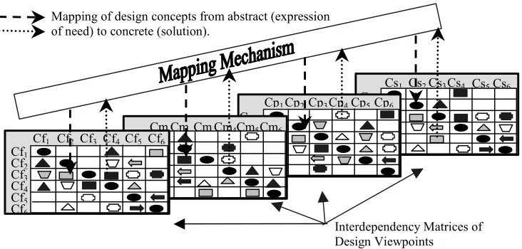
The three elements of the methodology described within Sections 4.1.1-4.1.3 are applicable to each of the design viewpoints separately. This results in the definition of a modular structure for individual viewpoints but not for the identification of the overall modularity of the product structure or maintenance of the modularity across viewpoints of the product structure. However to support the evolution of the modular design there is a requirement to map between the individual viewpoints. Thus, a mapping mechanism is defined to support cross-viewpoint modular development and analysis.
Cs1 Cs2Cs3Cs4 Cs5Cs6
Cs1
Cs2
Cs3
Cs4
Cs5
Cs6
Cp1Cp2Cp3Cp4Cp5Cp6
Cp1
Cp2
Cp3
Cp4
Cp5
Cp6
Cm1
Cm Cm
Cm2
Cm
Cm
Cm4
Cm4
Cm5
Cm5
Cm6
Cm6
Cf1
Cf1 Cf2
Cf2
Cf3
Cf3
Cf4
Cf4
Cf5
Cf5
Cf6
Cf6
Interdependency Matrices of Design Viewpoints
[image:14.612.129.495.70.245.2]Mapping of design concepts from abstract (expression of need) to concrete (solution).
Figure 7. Mapping mechanism.
The mapping mechanism consists of two parts, a modelling formalism and an optimisation mechanism. The modelling formalism consists of a knowledge formalism and a matrix formalism. The knowledge formalism is based on the previously described formalism within Section 4.1.1. However the focus here is on concepts and their cross-viewpoint dependencies, termed causal-link dependencies that represent the mapping of concepts between viewpoints as they progress from the abstract to the concrete. A causal link dependency can exist between any two concepts across any two of the three viewpoints of the design knowledge posited here. Again, due to the two dimensional limitations of the matrix formalism, only two of the three viewpoints can be represented in any one model. As such the matrix formalism differs from that previously defined in that each matrix represents concepts from two viewpoints and the causal-link dependencies between these. The resulting model is termed a Cross-Viewpoint Model.
The optimisation mechanism has consists of a Genetic Algorithm (GA) and a Cross-Viewpoint Clustering Criteria (CVCC). The CVCC is similar to that described within Section 4.1.3, however it is used to measure the sum of the distances between each two consecutive dependencies of each concept in both row and column. The GA alters the concept order, which in turn alters the positioning of the dependencies within the matrix.
4.2 Application
As the methodology was developed to support improved engineering design reuse, the procedural knowledge is defined based on its application within a current design activity (i.e. for reuse). The envisaged application process of the above methodology involves an iterative application loop which supports the generation of modules as the design evolves from the abstract to the concrete as shown in Figure 8. The design activity starts and knowledge is generated and utilised as the basis for the methodology’s modelling mechanism.
concept as a standalone entity. The process is repeated until all the remaining function viewpoint concepts have been verified.
On completion if the function viewpoint model verification process, the designer selects a GA structure on which to base the optimisation. The GA structure determines the population size, number of generations, and the mutation and crossover operators and probabilities. The aim is to generate an optimised function viewpoint model. The concept groupings defined in this model can be utilised as the basis to define and allocate further design tasks required to evolve the design activity and its associated knowledge, for example, the function concept groupings may be utilised as the basis to define the boundaries for individual designers and/or design teams, to research potential working principle or solution concepts to realise these functional groups. However, in complex or highly constrained problems, the concept grouping boundaries may not always be clearly visible from the optimised function viewpoint model and the designer can apply the module identification mechanism to facilitate this process. The module identification mechanism provides an interpretation of the modularity within the product structure. In this instance, the application of the module identification mechanism results in a modular structure for the function viewpoint. The modular structure model enables the designer to clearly interpret the inherent modularity of the product structure including hierarchical modularity and the differing modular configurations available to the designers. Again, this knowledge can be utilised to define the boundaries of the further design tasks required to evolve the design activity towards a successful conclusion.
The modular analysis of the function viewpoint can provide knowledge required to define tasks to evolve the design activity and contribute to the associated evolutionary design knowledge. The designers may then generate knowledge of the working principle concepts required to realise the function concept groupings.
The working principle concepts can be analysed both as an individual model of a viewpoint (a working principle viewpoint model) and with respect to its capabilities to maintain the modular solution. The analysis of the working principle viewpoint model is carried out through the same process as that described above for the function viewpoint model. The analysis results in knowledge of optimum working principle groupings on which to base further design tasks and research required to support the realisation of these groupings as structural entities, i.e. solution concepts or parts. The analysis of the capabilities of working principle concepts to maintain the modular solution defined in the function viewpoint is achieved through the application of the methodology’s mapping mechanism.
The mapping mechanism analyses the working principle concepts that have been defined by the designers to realise the function concepts. As such, the results (the concept order) defined in the optimised function viewpoint model is utilised as the basis for the analysis. A matrix formalism is applied to both the function and working principle concepts. The cross-viewpoint dependencies between these are defined and represented within the matrix body. The analysis begins with the designer checking all the dependencies between the function and working principle concepts. The designer queries if the concepts in each viewpoint have at least one more working dependency with the concepts from the alternative viewpoint, i.e. whether each working principle concept realises (or partially realises) a function concept and whether each function concept is realised by at least one working principle concept. Each concept in a preceding, more abstract viewpoint should be realised by one or more concepts in the following more concrete viewpoint to maintain the integrity of the design. For example, if a function concept is not realised by a concept in the working principle viewpoint, the design will evolve without embodying aspects of the defined functionality.
Methodology Elements Generate Design Ideas Knowledge Formalism Module Formalise Viewpoint Concepts, Relation, Constraints, Attributes Analyse Interdependency Matrix Pick Redundant Elements Choose Clustering Parameters Matrix Application Module Generate Viewpoint Modules Apply Interdependency Matrix Clustering/ Grouping Module Allocate Design Activities Based on
Defined Modules Evolved Design Model Store Version for Re-use Mapping Module Assess Importance Is Design Complete Disregard Check Consistency YES YES NO NO Consistency Maintained? OR Design Activity Design Model Question Decision Activity
Methodology Element Design Process
[image:16.612.85.521.73.473.2]Design/ Process KEY:
Figure 8. Methodology application process.
The process is repeated for the individual structure viewpoint and a mapping from the working principle viewpoint to the structure viewpoint. This application to the function, working principle and structure viewpoints represents one cycle of the methodology itself. However, the design activity is an iterative process and the designer’s knowledge of a design from a particular viewpoint evolves as the design progresses. Thus, the designer generates knowledge of more concrete and detailed viewpoint concepts as the design evolves.
5 Conclusion
A novel multi-viewpoint modular design methodology has been developed, based on the phenomena of modular design support for engineering design reuse, to fulfil the objective of developing and defining a multi-viewpoint modular design methodology. The methodology was developed with the aim of addressing the limitations of existing modular design approaches and satisfying the identified requirements.
modelling evolutionary design knowledge for analysis, modular optimisation to identify inherent modularity and map between design viewpoints to maintain the modular solution.
The multi-viewpoint modular design methodology embodies four main elements: a modelling formalism, an optimisation mechanism, a module identification mechanism and a viewpoint mapping mechanism. The overall methodology defines the declarative and procedural knowledge required to fuse the methodology elements into a coherent framework and provide an articulate procedure for designers to follow in practice.
The modelling mechanism embodies a previously developed evolutionary knowledge formalism that supports current working knowledge and a dependency structure matrix to provide a representation, termed a viewpoint model, on which to support a modular analysis.
The module identification mechanism embodies a module strength indicator function and an alternative representation of the design model termed the module structure matrix, The module strength indicator function and application process is based on the formalism of a definition of modularity extracted from the identified characteristics of modular design. The module strength indicator values are interpreted and modelled to produce a modular structure model, an alternative representation of the viewpoint model. The methodology was developed within the aim of addressing the limitations of existing modular design approaches and satisfying the identified requirements. To fulfil the objective of evaluating the functionality of the developed approach, it was partially realised within a computational environment and implemented within two industry based engineering design processes [15], [33]. The results of both implementations identified potential improvements in the modularity of the designs. In addition, the methodology was deemed by the industrial partners involved to provide an articulate procedure for practising designers [15].
References
1. Duffy, A.H.B., A.F. Ferns. An Analysis of Design Re-use Benefits. in 12th International Conference on Engineering Design. 1999. Munich Germany.
2. Duffy, A.H.B., J.S. Smith, S.M. Duffy. Design Reuse Research - A Computational Perspective. in Engineering Design Conference on Design Reuse. 1998.
3. Smith, J.S., A.H.B. Duffy. Re-using Knowledge - Why, What and Where. in 13th International Conference on Engineering Design. 2001. Glasgow, UK.
4. Sosale, S., M. Hashemian, P. Gu, Product modularisation for re-use and recycling. Concurrent Product Design and Environmentally Conscious Manufacturing, 1997.
5. O'Grady, P., W.Y. Liang, An object oriented approach to design with modules. Computer Integrated Manufacturing Systems, 1998. 11(4): p. 267-283.
6. Miller, T.D., P. Elgard. Structuring principles for the designer - balancing product performance with process efficiency. in 1999 CIRP International Design Seminar: Integration of Process Knowledge into Design Support Systems. 1999: Kluwer Academic.
7. Elgard, P., T.D. Miller. Designing product families. Design for integration in manufacturing. in 13th IPS Research Seminar. 1998. Aalborg University, Fugsloe.
8. Galvin, P., Product modularity, information structures and the diffusion of innovation. International Journal of Technology Management, 1999. 17(5): p. 467-479.
9. Muffato, M., Introducing a platform strategy in product development. International Journal of Production Economics, 1999. 60: p. 145-153.
10. Chang, W. Design-in-modularity with conceptual robustness. in Design Engineering Technical Conferences. 1995: ASME.
11. Miller, T.D. Modular engineering in production plants. in 12th International Conference on Engineering Design. 1999. Munich, Germany.
13. Miller, T.D., P. Elgard. Defining modules, modularity and modularisation - evolution of the concept in a historical perspective. in 13th IPS Research Seminar. 1998. Aalborg University, Fugsloe.
14. Huang, C.C., A. Kusiak, Modularity in design of products and systems. IEEE Transactions on Systems, Man, and Cybernetics - Part A: Systems and Humans, 1998. 28(1): p. 66-77.
15. Smith, J.S., A multiple viewpoint modular design methodology, in Design Manufacture and Engineering Management. 2002, University of Strathclyde: Glasgow. p. 213.
16. Duffy, A.H.B., S.M. Kerr. Customised perspectives of past designs from automated group rationalisations. in Artifical Intelligence in Engineering Design. 1993.
17. Manfaat, D., A.H.B. Duffy, SPIDA: abstracting and generalising layout design cases. Artificial Intelligence for Engineering Design, Analysis, and Manufacturing, 1998. 12: p. 141-159.
18. Kusiak, A., C. Huang, Development of modular products. IEEE Transactions of Components, Packaging and Manufacturing Technology, 1996. 19(4): p. 523-538.
19. Ouyang, M., L. Chenggang. Intelligent CAD approach for modular design. in SPIE - The International Society for Optical Engineering. 1996.
20. Erixon, G. Modular function deployment. in 2nd WDK Workshop on Product Structuring. 1996. Delft, Netherlands.
21. Gu, P., M. Hashemian, An integrated modular design methodology for life-cycle engineering. CIRP Annals, 1997. 46(1): p. 71-74.
22. Kamrani, A.K. Modular design methodology for complex parts. in 6th IIE Annual Engineering Research Conference. 1997. Florida, USA.
23. Ishii, K., B.H. Lee, Design for product retirement and modularity based on technology life-cycle. Manufacturing Science and Engineering, 1995. 3(2): p. 921-933.
24. Jarventausta, S., A. Pulkkinen. Enhancing product modularisation with multiple views of decomposition and clustering. in Design for Configuration 5th WDK Workshop on Product Structuring. 2001: Springer Verlag.
25. Salheih, S.M., A.K. Kamrani, Macro level product development using design for modularity. Robotics and Computer Integrated Manufacturing, 1999. 15: p. 319-329.
26. Tseng, M.M., J. Jiao, Case based evolutionary design for mass customisation. Computers and Industrial Engineering, 1997. 33(1-2): p. 319-323.
27. Ulrich, K.T., S.D. Eppinger, Product Design and Development. 1995, New York, USA: McGraw Hill.
28. Pahl, G., W. Beitz, Engineering Design - A Systematic Approach. 1996: Springer Verlag.
29. Finger, S. Design re-use and design research. in Design Reuse Engineering Design Conference. 1998. Brunel University, UK.
30. Mostow, J., M. Barley, Automated reuse of design plans. Artificial Intelligence for Engineering Design, Analysis, and Manufacturing, 1993: p. 2-15.
31. Jiao, J., M.M. Tseng, A methodology of developing product family architecture for mass customisation. Journal of Intelligent Manufacturing, 1999. 10: p. 3-20.
32. Zhang, Y., Design Knowledge Structuring. 1998, University of Strathclyde: Glasgow. p. 40. 33. Whitfield, R.I., J.S. Smith, A.H.B. Duffy. Identifying component modules. in Artificial
![Figure 1. Customised viewpoint approach in design [16].](https://thumb-us.123doks.com/thumbv2/123dok_us/1716263.125017/5.612.148.467.218.495/figure-customised-viewpoint-approach-design.webp)
![Figure 3. Views of the product model [24] and customised views [16].](https://thumb-us.123doks.com/thumbv2/123dok_us/1716263.125017/8.612.95.530.78.370/figure-views-product-model-customised-views.webp)
![Figure 4. Multi-viewpoints of CWK in design [32].](https://thumb-us.123doks.com/thumbv2/123dok_us/1716263.125017/11.612.139.478.323.456/figure-multi-viewpoints-cwk-design.webp)