i
PERFORMANCE ANALYSIS OF CASCADED OPTICAL AMPLIFIER WITH DIFFERENT LOOP LENGTH
ARHAM MUSTAQEEM BIN ISMAIL
This Report Is Submitted In Partial Fulfillment of Requirement for the Bachelor Degree of Electronic Engineering (Electronic Telecommunication) with Honours
Faculty of Electronic and Computer Engineering Universiti Teknikal Malaysia Melaka
v
Special dedicate:
vi
ACKNOWLEDGEMENT
Firstly, I would like to express my deepest thank to my supervisor, Mr Fauzi Bin Haji Abdul Wahab who had guided me a lot of task during two semesters. Besides that, thanks to the lectures and staffs from Faculty of Electronic and Computer Engineering for their cooperation, valuable information, suggestion and guidance during my research to complete this final year project.
Deepest thanks and appreciation to my family for their cooperation, encouragement, constructive suggestion and full of support for the report completion, from the beginning till the end. Thanks to all of my friends and everyone, those have been contributed by supporting my work and help myself during the final year project progress till it is fully completed.
vii
ABSTRACT
viii
ABSTRAK
ix
TABLE OF CONTENT
TITLE PAGE PAGE
PROJECT TITLE i
DECLARATION ii
DEDICATION iv
ACKNOWLEDGEMENT v
ABSTRACT vi
ABSTRAK vii
TABLE OF CONTENT ix
LIST OF TABLE xii
LIST OF FIGURE xiii
x
CHAPTER I: INTRODUCTION 1
1.1 Project Background 1
1.2 Problem Statement 2
1.3 Scopes of the project 3
1.4 Objectives 3
1.5 Thesis Structure 4
CHAPTER II: LITERATURE REVIEW 5 2.1 Introduction to Optical Communication 5 2.2 Introduction to Optical Amplifier 8
2.3 Erbium-Doped Fiber Amplifier 9 2.3.1 Principle of EDFA 10
2.3.2 Configuration of EDFA 12
2.4 Raman Amplifier 15
2.4.1 Principle of Raman Amplifier 16
2.4.2 Configuration of Raman Amplifier 18
CHAPTER III: METHODOLOGY 19
3.1 Project Identification 19
xi
3.1.2 Design of Circuit 20
3.1.3 Simulation of Circuit 21
3.1.4 Performance Analysis 22
CHAPTER IV: RESULT & DISCUSSION 23
4.1 Single Stage Optical Amplifier 23
4.1.1 Single Stage Erbium Doped Fiber 23
4.1.2 Single Stage Raman Amplifier 26
4.2 Two Stage Amplifier 29
4.2.1 Cascaded Erbium Doped Fiber Amplifier 31
4.2.2 Cascaded Erbium Doped Fiber Amplifier and 32
Raman Amplifier 4.2.3 Cascaded Raman Amplifier and Erbium 34
xii
CHAPTER IV: CONCLUSION & RECOMMENDATION 38
xiii
LIST OF TABLE
TABLE TITLE PAGE
2.1 Advantage of Optical Fiber 8 4.1 Comparison of Eye-diagram for Single Stage Raman Amplifier using 26 Different wavelength
4.2 Comparison of Eye-diagram for Single Stage EDFA using different 28 Wavelength
4.3 Comparison of Eye-diagram for Two Stage Cascaded EDFA-EDFA 31 Using different wavelength
4.4 Comparison of Eye-diagram for Two Stage Cascaded RAMAN-EDFA 33 Using different wavelength
xiv
LIST OF FIGURE
FIGURE TITLE PAGE
2.1 Diagram of Optical Amplifier 5
2.2 Block Diagram for Optical Transmission System Using Regenerator 8 2.3 Hardware of EDFA 2.4 Energy level in Erbium 14
2.5 Forward Pumping Configuration for EDFA 15
2.6 Backward Pumping Configuration for EDFA 17
2.7 Bidirectional Pumping Configuration for EDFA 18
4.1 Circuit Configuration for Single Stage Discrete Raman Amplifier 19
4.2 Circuit Configuration for Single Stage EDFA 19
4.3 Circuit Configuration for Cascaded EDFA-EDFA 19
xv
LIST OF GRAPH
GRAPH TITLE PAGE
4.1 Graph of Gain and Noise Figure versus Length for Single 24 Stage Raman Amplifier
4.2 Graph of Output Power versus Length for Single Raman Amplifier 25 4.3 Graph of Gain and Noise Figure versus Length for Single Stage 27
EDFA
4.4 Graph of Output Power versus Length for Single Stage EDFA 27 4.5 Graph of Gain and Noise Figure versus Length for Two Stages 29 Cascaded EDFA-EDFA
4.6 Graph of Output Power versus Length for Two Stages 30 Cascaded EDFA-EDFA
4.7 Graph of Gain and Noise Figure versus Length for Two Stages 32 Cascaded Raman-EDFA
xvi
Cascaded Raman-EDFA
4.9 Graph of Gain and Noise Figure versus Length for Two Stages 34 Cascaded EDFA-Raman
5.0 Graph of Output Power versus Length for Two Stages 35 Cascaded EDFA-Raman
5.1 Graph of Gain and Noise Figure versus Length for Two Stages 36 Cascaded Raman-Raman
5.2 Graph of Output Power versus Length for Two Stages 36 Cascaded Raman-Raman
1
CHAPTER 1
INTRODUCTION
1.1Project Background
Optical amplifiers will play an important role in future optical transmission system in telecommunication. Optical amplifier, different from the conventional repeater, amplifies the optical signal from the optical sources directly without the need to undergo the conversion process of optical to electrical and electrical to optical signal. It is also come with simpler structure and lower cost compare with conventional
regenerative repeater. In this project, two types of optical amplifier; Erbium-Doped Fiber Amplifier (EDFA) and Raman Amplifier have been selected and extensively tested based on several parameters.
2
the best choice of transmitting the optical signal because it results less signal losses , even in long distance transmission system. The value of wavelength between 1530 nm and 1590 nm will be use, covering the C and L-band of transmission system. The pump wavelength and pump power for the optical amplifier are used based on the previous journals that has been studied. The statistic analysis involved in this project is: gain, Noise Figure (NF), quality factor (Q-Factor) and Optical Signal-To-Noise Ratio (OSNR).
1.2Problem Statement
Before the optical amplifier was invented, the signal repeater was using
semiconductor devices to convert optical signal to electrical signal before amplifying the signal. However, this process produce a lot of noise, results the poor reception of optical signal. When the signal are measured with eye diagram, the shapes are scattered, which indicates the poor reception of the optical signal. So, in this project, Raman and EDFA will be used to substitute the regular signal repeater. These optical amplifiers were used to eliminate the conversion between optical-electrical and electrical-optical.
Nowadays, most optical transmission system has been implemented in the range of C-band wavelength (1530 nm - 1560 nm) or 1550nm to be specific. This is
particularly due to two main factors; the loss for the silica based fiber is said to be the lowest and the performance of Erbium-Doped Fiber Amplifier (EDFA) is considered as optimum to operate around that range of wavelength. However, due to the introduction of Wavelength Divison Multiplexing (WDM ) system, where multiple number of input signals can be transmitted simultaneously in a single fiber, the use of this band need to be expanded. This limitation of EDFA contributes to the shift of interest by the
3
EDFA can operate at any band of transmission wavelength. The major problem encountered by Raman Amplifier is, it needs a very high value of pump power to produce a good performance. Moreover, a multi pump wavelength needs to be added to the configuration to ensure the amplifier can produce a large bandwidth in terms of amplifier gain. In this project, a configuration of Raman Amplifier will be designed and its performance in C-Band and L-Band wavelength will be extensively tested and directly compared with the performance of EDFA.
1.3Scopes of Project
The project will focus on 4 mains area:
I. Literature review of optical amplifier
II. Circuit design and simulation for optical amplifier using OptiwaveOptisystem software
Single Stage EDFA
Single Stage Raman Amplifier Two Stage Cascaded EDFA-EDFA Two Stage Cascaded EDFA-Raman Two Stage Cascaded Raman-EDFA Two Stage Cascaded Raman-Raman
III. Analyse the circuit using different loop length
4
1.4Objectives
I. To design and analyze the performance of cascaded amplifier with different loop length
II. To demonstrate and extensively tested the operating performance of cascaded optical amplifier in C-Band (1530nm-1565nm) and L-Band
5
CHAPTER 2
LITERATURE REVIEW
2.1 Introduction to Optical Communication
Since been first commercially used in 1970s and early 1980s, optical
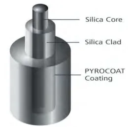
[image:22.612.284.414.551.680.2]communication system has shaped today’s world, covering almost 80 percent of long distance data transmission and voice communication. Optical communication system basically consists of transmitter and receiver, connecting by optical fiber. Fiber optic is mainly made from silica for a long transmission distance communication purpose whereas plastic optical fiber can be used for short distance communication.
6
A basic optical communication link comprises a transmitter and receiver, with an optical fiber cable connecting them. Although signals propagating in optical fiber suffer far less attenuation than in other mediums, such as copper, there is still a limit of about 100 km on the distance the signals can travel before becoming too noisy to be
detected[1-2].
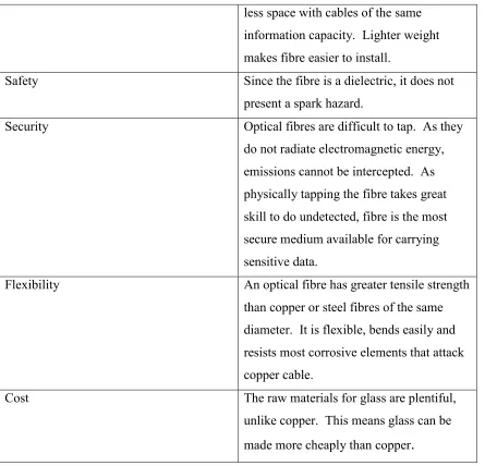
Characteristics
Bandwidth Fibre optic cables offer a much greater
bandwidth than metal cables. With the high performance single mode cable used by telephone industries for long distance telecommunication, the bandwidth
surpasses the needs of today's applications and gives room for growth tomorrow.
Low Power Loss An optical fibre offers low power
loss. This allows for longer transmission distances. In comparison to copper; in a network, the longest recommended copper distance is 100m while with fibre, it is 2000m.
Interference The transmission of data using optical
fiber is carry on without the presence of electrical charge. Thus, electrical noise can be neglected.
Size In comparison to copper, a fibre optic
cable has nearly 4.5 times as much capacity as the wire cable has and a cross sectional area that is 30 times less.
Weight Fiber optic cables are much thinner and
7
less space with cables of the same information capacity. Lighter weight makes fibre easier to install.
Safety Since the fibre is a dielectric, it does not
present a spark hazard.
Security Optical fibres are difficult to tap. As they
do not radiate electromagnetic energy, emissions cannot be intercepted. As physically tapping the fibre takes great skill to do undetected, fibre is the most secure medium available for carrying sensitive data.
Flexibility An optical fibre has greater tensile strength
than copper or steel fibres of the same diameter. It is flexible, bends easily and resists most corrosive elements that attack copper cable.
Cost The raw materials for glass are plentiful,
[image:24.612.109.554.67.495.2]unlike copper. This means glass can be made more cheaply than copper