full papers
Isotope Substitution Extends the Lifetime of Organic
Molecules in Transmission Electron Microscopy
Thomas W. Chamberlain , Johannes Biskupek , Stephen T. Skowron , Peter A. Bayliss ,
Elena Bichoutskaia , * Ute Kaiser , * and Andrei N. Khlobystov *
1. Introduction
Aberration-corrected high-resolution transmission electron microscopy (AC-HRTEM) has the potential to become a pow-erful method for imaging individual molecules with atomic resolution. AC-HRTEM provides complete structural infor-mation about the whole molecule, not just its surface, with the
DOI: 10.1002/smll.201402081
S
tructural characterisation of individual molecules by high-resolution transmission
electron microscopy (HRTEM) is fundamentally limited by the element and electron
energy-specifi c interactions of the material with the high energy electron beam. Here,
the key mechanisms controlling the interactions between the e-beam and C–H bonds,
present in all organic molecules, are examined, and the low atomic weight of hydrogen—
resulting in its facile atomic displacement by the e-beam—is identifi ed as the principal
cause of the instability of individual organic molecules. It is demonstrated theoretically
and proven experimentally that exchanging all hydrogen atoms within molecules
with the deuterium isotope, and therefore doubling the atomic weight of the lightest
atoms in the structure, leads to a more than two-fold increase in the stability of organic
molecules in the e-beam. Substitution of H for D signifi cantly reduces the amount of
kinetic energy transferred from the e-beam to the atom (main factor contributing to
stability) and also increases the barrier for bond dissociation, primarily due to the
changes in the zero-point energy of the C–D vibration (minor factor). The extended
lifetime of coronene-d
12, used as a model molecule, enables more precise analysis of the
inter-molecular spacing and more accurate measurement of the molecular orientations.
Transmission Electron Microscopy
T. W. Chamberlain, S. T. Skowron, P. A. Bayliss, E. Bichoutskaia, A. N. Khlobystov
School of Chemistry
The University of Nottingham, University Park Nottingham NG7 2RD , UK
E-mail: [email protected]; [email protected] J. Biskupek, U. Kaiser
Electron Microscopy of Materials Science Central Facility for Electron Microscopy Ulm University
Albert Einstein Allee 11 Ulm 89081 , Germany E-mail: [email protected]
A. N. Khlobystov
Nottingham Nanotechnology & Nanoscience Centre University of Nottingham
University Park Nottingham NG7 2RD , UK
This is an open access article under the terms of the Creative Commons Attribution License, which permits use, distribution and reproduction in any medium, provided the original work is properly cited.
The copyright line for this article was changed on 31 July after original online publication.
spatial resolution reaching the sub-Ångstrøm scale. Atomi-cally thin carbon structures such as graphene, [ 1–4 ] graphene
oxide [ 5–7 ] or single-walled carbon nanotubes (SWNT) [ 8–14 ]
have been demonstrated as excellent substrates for molecules, providing mechanical support, effi cient reduction of ionisation and suppression of molecular motion, thus enabling atomically resolved AC-HRTEM analysis at the single-molecule level.
These latest achievements illustrate the potential of AC-HRTEM to rival traditional spectroscopic methods of struc-tural characterisation of molecular materials, provided that a crucial obstacle related to the invasive and destructive nature of the electron beam (e-beam) is overcome. The elastic for-ward scattering of the accelerated electrons of the e-beam by atoms of the sample molecules provides the main contribu-tion to the imaging signal in HRTEM, however it can also cause so-called knock-on damage manifested in the ejection of atoms from the molecules, which typically leads to decom-position of the intrinsic structure faster than AC-HRTEM images can be captured. [ 15,16 ] To interpret experimental
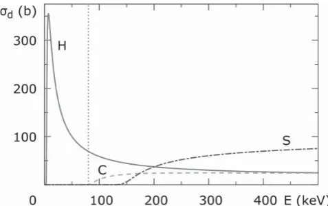
knock-on damage, the important quantity to consider is the ejection cross-section of an atom in the molecule, σd , which depends strongly on the kinetic energy of incident electrons ( Figure 1 ), a fraction of which will be transferred to the atom in an elastic scattering event. [ 17–19 ] At an e-beam energy of
200 or 300 keV, commonly utilised in TEM, light and medium atomic weight elements that constitute the vast majority of molecular compounds are highly susceptible to ejection. However, a sharp decrease of σd for most elements when the
energy of the e-beam is lowered [ 20 ] has the consequence that
most of the studies on carbon-based materials in an aberra-tion-corrected TEM are nowadays performed at voltages of 80 kV or 60 kV [ 21,22 ] and even below. [ 23,24 ]
For example σd for sp 2-carbon within graphitic
struc-tures approaches zero at the e-beam energy of about 80 keV (Figure 1 ) making it in principle possible to image carbon-based molecules using an e-beam set at or below this energy without perturbing their structures. [ 25 ] All other elements
behave in a similar way to carbon under the e-beam, with the exception of hydrogen, which exhibits a dramatic increase in the ejection cross section at lower energies (Figure 1 ). While carbon and other elements within the molecule become more stable with reduction of the energy of the incident electrons, the probability of ejection of hydrogen atoms increases sharply. At and below 80 keV (optimum for carbon) H-atoms are removed instantaneously, thus making imaging of undamaged
other elements creates a fundamental barrier to atomic-res-olution imaging of individual small organic molecules, which represent building blocks for biomacromolecules [ 26–28 ] and
molecular materials, such as polymers. In this study we provide a simple and elegant solution to this seemingly insurmountable challenge by substituting the most common protium isotope of hydrogen in organic molecules for the deuterium isotope. Iso-topic substitution has no effect on the molecular structure but increases the atomic weight of the hydrogen atoms by 100% which drastically increases the stability of the molecules in the e-beam, allowing imaging of individual molecules.
2. Results and Discussion
It is important to explore the physical origin of the unusually large susceptibility of hydrogen atoms to knock-on damage by the e-beam. The classical Rutherford electron scattering cross-section describes the probability of an incident electron being elastically scattered by an atom: [ 29 ]
σ πε
β
β
( )
θ= ⋅
⋅ ⋅ ⋅ ⎛
⎝⎜4 2 ⎞⎠⎟ − ⋅
1 2 2 0 2 2 2 4 4 z e
m c CSC
R
e
(1)
where z is the nuclear charge, β = v e / c is the ratio of electron velocity v e to the speed of light, c , θ is the electron scattering
angle and m e is the mass of an electron. The expression (1)
was expanded [ 30 ] to improve the accuracy:
σ θ
( )
=σ ⎝⎜⎛1−β sin( )
θ +π β( )
θ ⎛⎝⎜ −( )
θ ⎞⎠⎟⎞⎠⎟2 sin 2 1 sin 2 2 2 ze2
c
R
(2)
The amount of kinetic energy T transferred from the inci-dent electron to an atom in a collision leading to elastic scat-tering is expressed by the formula:
θ
(
)
(
)
(
)
= ⋅ ⋅ + ⋅ + ⋅ + ⋅ ⋅ 2 22 sin / 2 , 2
2 2
2
T M E E m c
M m c M E
e e
(3)
where M is the mass of the atom, and E is the electron kinetic energy.
Generally, the atom is only ejected from the molecule by the e-beam, leading to irreversible knock-on damage, if the transferred energy T is greater than an ejection energy threshold, E d , related to the strength of interatomic bonding within the molecule. The atom ejection cross-section can then be obtained by integrating σ expressed through T using Equations ( 2) and ( 3) in the energy range T > E d :
∫
σ σ π π
πε β β β π β
{
( )
( ) ( )
( )
= ⋅ = ⋅ ⋅ ⋅ ⋅ ⎛ ⎝⎜ ⎞⎠⎟ − − − ⋅ + ⋅⋅ ⎡ − − ⎣ ⎢ ⎤ ⎦ ⎥⎫⎬⎪ ⎭⎪ > 4 4 4 2.1 1 ln
2 ln 2
max
2
0 2
2
4
max 2 max
2
max 1/2 max
[image:2.595.48.287.57.207.2]T T dT z e m c T E T E z e c T E T E d e T E d d d d d (4)
full papers
www.MaterialsViews.com
where T max is the maximum transferrable energy from the
e-beam to an atom, which corresponds to θ = 180°, and ∀ is the reduced Planck constant h/2π . This equation demonstrates that the stability of an atom to the e-beam has a complex dependence on both the nuclear charge and mass of the ele-ment (included in the T max parameter) and the energy of the
electron beam (included in β and T max ). The fi rst term in Equa-tion ( 4) resembles σR, which is proportional to z 2 of the atom:
from this term alone lighter elements are expected to interact less with the e-beam, which may lead to the incorrect conclu-sion that lighter elements are less susceptible to knock-on damage. However, the effect of T max , which is inversely pro-portional to atomic weight M , effectively counteracts the fi rst term; signifi cantly more kinetic energy is transferred from the e-beam to lighter atoms than heavier ones (Equation ( 3) ). Ulti-mately, the balance between E d and T max is most important: if at a certain energy of the e-beam the maximum transferrable energy is below the ejection threshold, the chance of knock-on damage is zero (σd = 0) meaning that the molecule will be stable indefi nitely during AC-HRTEM imaging. As hydrogen is the lightest element in the Periodic Table, the value of
T max (H) is substantially higher than for other elements
(com-pare T max ( 1 H) = 188 eV and T
max (C) = 16 eV under an 80 keV
e-beam). σd for hydrogen does not reach zero or any
reason-ably low value at any energy of the e-beam (Figure 1 ), which makes TEM imaging of structurally intact organic molecules practically impossible.
This analysis proves that the lack of stability of hydrogen atoms in molecules under the e-beam is related primarily to the low atomic weight of the H-atoms. One way to address this problem and therefore increase the stability of organic molecules in the e-beam is to replace the protium isotope of hydrogen in the molecule with heavier isotopes. Substitution of naturally abundant hydrogen (>99.9% 1H protium
iso-tope) for deuterium D ( 2 H isotope) which contains an
addi-tional neutron, doubles the atomic weight of a D-atom with respect to 1 H. The structure and chemical properties of
deu-terated organic molecules are thus identical to their 1 H
ana-logues, but their stability in the e-beam should be signifi cantly enhanced due to a lowering of the T max parameter and thus an overall decrease of σd . In many cases isotope exchange
readily takes place when organic molecules are treated with heavy water D 2 O, offering a universal methodology for stabi-lising organic molecules for AC-HRTEM imaging.
To illustrate this principle, coronene was chosen as a model molecule as it has been studied by TEM pre-viously [ 31–35 ] and is observed to decompose very fast
upon e-beam irradiation at energies of 80–120 keV. [ 32 ] The
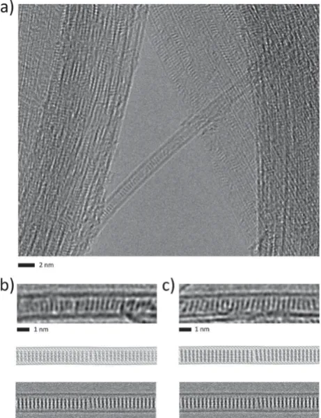
disk-like shape of coronene is easily recognisable in AC-HRTEM images and spontaneously forms stacks within the nanotube cavity, orienting molecular planes parallel to the direction of the e-beam ( Figure 2 a, and further on below). Although all 12 C–H bonds in coronene are chemically equivalent, the e-beam affects H-atoms in different ways depending on the angle between the individual C–H bond and the e-beam, leading to different values of E d (Figure 2 b).
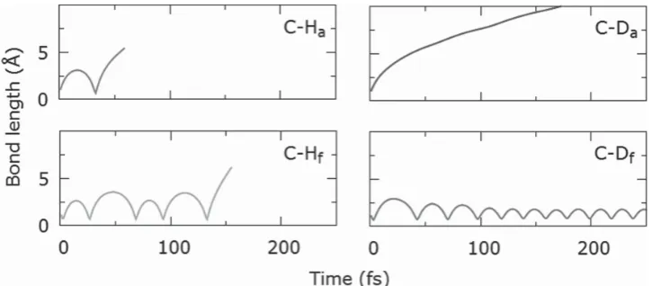
Ab initio molecular dynamics (AIMD) has been used to calculate the values of E d for ejections of hydrogen and deuterium atoms from coronene. These simulations demon-strate that the bonds parallel to the e-beam, such as C–H a
and C–H f (see Figure 2 b), are more susceptible to e-beam
damage than other bonds. For protium isotope these bonds have the lowest ejection threshold of E d (H) = 6.1 eV as the momentum of the e-beam is transferred directly along the bonds. This makes them the weakest points in the molecule and the subsequent H loss is the trigger for decomposition of coronene. It is interesting that regardless of whether the momentum is transferred in the direction of bond contrac-tion (as in the case of C–H f ) or bond stretching (as in the
case of C–H a ), the value of E d remains the same ( Figure 3 ). The isotopic substitution of hydrogen for deuterium leads to a nearly 30% increase in E d , from E d (H) = 6.1 eV in C–H a
bond to E d (D) = 7.8 eV for the C–D a bond, which is related to
the decreased zero-point vibrational energy E 0 for C–D bonds, making them more diffi cult to break (this forms the basis for differences in reactivity between isotopes in chemistry):
π
(
( )
( )
(
(
)
)
)
=⋅ +
4 0
E h k
M C M H or D
M C M H or D
(5)
where k is the force constant, and M is the atomic weight of carbon, protium or deuterium respectively.
Under the e-beam a marked difference between the C–D a and C–D f bonds is observed: while the e-beam can
still break the C–D a bond (albeit with lower probability than C –H a ), the energy transferred to the deuterium atom in the
C–D f bond does not ricochet to bond dissociation as in the
case of C–H f but effectively dissipates through the molecule,
leading to temporary structural deformations with no irre-versible damage (Figure 3 ). In addition, the bond dissocia-tion mechanism of the C–D a bond is different to that of the
C–H a bond. While in the case of the C–H a bond the
trans-ferred energy leads to multiple bond stretches eventually
leading to dissociation, in the case of the C–D a bond the
deuterium atom is removed directly with no contraction of the bond. Hence, both C–H a and C–H f bonds for coronene,
and only C–D a bonds for coronene-d 12 are considered to be the most susceptible to knock-on damage, and as a result the cross sections associated with removal of these atoms were used to quantify the molecules stability in the e-beam.
A combination of the increase in the ejection threshold energy E d and a signifi cant decrease in the value of T max has a profound impact on the ejection cross section σd for
deu-terium ( Figure 4 , dashed-dotted trace). For example, com-paring the C–H a and C–D a bonds, the likelihood of ejection of deuterium is fi ve times lower when compared to protium at the maximum of the cross section function (Figure 4 ).
It is instructive to compare the ejection cross sections of H and D in the range of e-beam energies between 80 and 100 keV because as the energy of e-beam decreases, the carbon frame-work of the molecules becomes infi nitely stable in this range
( σd (C) → 0 just below 100 keV, Figure 3 , inset). The
cross-section of deuterium versus protium ejection from the most vulnerable bond in coronene is approximately 2.77 times higher at 80 keV and 2.74 times at 100 keV, indicating that deuterium can potentially withstand a nearly three times higher dose of electrons in the range of e-beam energies typi-cally used for AC-HRTEM imaging compared to hydrogen.
In practical terms, the value of σd for the most easily broken chemical bond within a molecule and typical values of the e-beam dose rate j required for AC-HRTEM imaging can be used to estimate the time required for ejection of the fi rst atom from the molecule (e.g. in the chemical kinetics terms, the ejection of fi rst atom from coronene is likely to be a rate-controlling step for the decomposition of molecules within the stacks), t ev , under the e-beam: [ 36 ]
= σ
1
t jn
ev
d
(6)
where n is the number of bonds of such type in the molecule. Considering that ejection of an atom from the organic mol-ecule leads to highly reactive radical spe-cies causing rapid decomposition, t ev gives a good estimate for the observed life-time of the molecule under the e-beam. Our calculations predict that under the same external conditions (same energy and dose rate of the e-beam) deuterated molecules should be 2–3 times more stable than the protium analogues, which should manifest in a 2–3-fold increase in the total e-beam dose they can tolerate and subsequently lead to a substantial increase in their life-time under the e-beam ( Table 1 ).
Recent AC-HRTEM measurements on
13 C enriched graphene have recently
ena-bled more accurate evaluation of cross sec-tion for the carbon lattice, but had only a marginal effect on the stability of graphene
Figure 3. Variation of the C–H and C–D bond lengths with time calculated by AIMD after momentum corresponding to the E d of C–H a ( E d = 6.1 eV) and C–D a ( E d = 7.8 eV) was transferred to the different protium atoms of coronene and the deuterium atoms of coronene-d 12 respectively. Bonds are broken in the cases of C–H a , C–H f and C–D a , but not C–D f .
[image:4.595.113.476.57.216.2]full papers
www.MaterialsViews.com
in the e-beam due to a relatively small difference in the atomic weights of 12C and 13 C. [ 37 ] However, an alternative model
describing the ejection of carbon atoms from graphene by a kinetic isotope effect (KIE) has recently been proposed which led to an unexpected conclusion that the graphene atomic lattice is extremely cold (∼25 K) in the ambient temperature AC-HRTEM measurements. [ 38 ] Since KIE emanates primarily
from the difference in the zero-point energies E 0 (Equation ( 5) )
as illustrated by our calculations for C-H and C-D (Figure 3 ), it is therefore accounted for by the total cross sections func-tion σd (Equation ( 4) ) as a part of the E d parameter. The
description of molecular transformations under the e-beam by
σd is all-inclusive (e.g. σd incorporates information about the
zero-point energy for chemical bonds which determines KIE and other kinetic effects, as well as the amount of transferred energy from the e-beam to a particular atom and the likeli-hood of this transfer) and being mathematically rigorous it enables the accurate analysis and prediction of rates and path-ways of transformations of molecules under the e-beam.
To verify this hypothesis and demonstrate its practical applicability, we prepared carbon nanotubes fi lled with stacks of coronene (coronene@SWNT) or deuterated coro-nene (corocoro-nene-d 12@SWNT) and compared their stability
in the 80 keV e-beam. The protium atoms of coronene were exchanged for deuterium atoms in near-critical D 2 O [ 40 ] and
the degree of isotope exchange was confi rmed by gas chro-matography mass spectrometry to be >99%. Coronene and coronene-d 12 were encapsulated in carbon nanotubes from
the gas phase using identical conditions, by heating the mole-cules and freshly opened SWNT at 400 °C in vacuum. Prior to AC-HRTEM analysis coronene@SWNT and coronene-d 12 @SWNT samples were washed with toluene to remove any
molecules from the surface of the nanotubes. The majority of nanotubes were densely fi lled with molecules in both cases (>95%), and the structures observed were essentially iden-tical with the coronene and coronene-d 12 molecules both
orientated at an angle of ~80° with respect to the nanotube sidewall ( Figure 5 ).
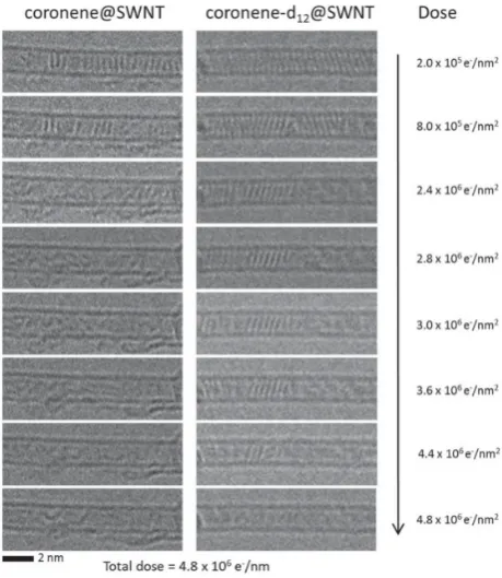
Qualitative AC-HRTEM observations indicate that coro-nene is signifi cantly less stable in the e-beam, decomposing into amorphous featureless structures extremely quickly, so that extra care is needed (low e-beam dose rate and short exposure time) to obtain its images (Figure 5 b), whereas cor-onene-d 12 (Figure 5 c) appears to be signifi cantly more stable. To quantify the enhancement in stability of C–D bonds with respect to C–H bonds, the dose rate of the 80 keV electron beam was set at 2·10 5 e − /nm 2 /s and time series images were
recorded for both samples ( Figure 6). Molecules of coro-nene and corocoro-nene-d 12 within the stacks were observed to
decompose under the e-beam at different rates. The evolu-tion of molecules in stacks was carefully monitored, and the cumulative dose of the e-beam required to destroy all mol-ecules within the stack was recorded in each experiment, as described in the Experimental Section. A number of different areas were analysed for each sample and showed at least a two-fold increase in the stability of the deuterated molecules ( Table 2 ). At a higher energy of 100 keV the difference in sta-bility of coronene and coronene-d 12 is even more pronounced,
with coronene decomposing almost instantaneously (ESI fi le).
The effects of isotope substitution were studied for crys-tals of coronene and coronene-d 12 . About 20 crystals of each
species were irradiated under identical imaging conditions and the loss of crystallinity was tracked as a function of dose rate by acquiring series of diffraction patterns ( Figure 7 ). The
[image:5.595.312.543.61.362.2]
Table 1. Ejection cross section ( σd ), time required for ejection of the fi rst atom ( t ev ), and total electron dose required for ejection of H, D and C atoms via knock-on damage in coronene and deuterated coronene calculated for different dose rates ( j ) of 80 or 100 keV e-beam.
Atom Energy of e-beam
[keV]
σd per atom
[barn]
j [e-/barn/s]
t ev [s]
Total e- dose
[e/nm 2 ]
H 80 84.87 0.0001 59 5.89·10 7
0.0005 12
100 71.80 0.0001 70 6.96·10 7
0.0005 14
D 80 30.59 0.0001 163 1.63·10 8
0.0005 33
100 26.18 0.0001 191 1.91·10 8
0.0005 38
C 80 0.00 0.0001 ∞ ∞
0.0005 ∞
[image:5.595.55.294.104.277.2]100 5.83 × 10 −3 0.0001 37015 3.70·10 10
experiments were always stopped at the point where no crys-talline lattice refl ections were visible and the irradiated areas were completely amorphous. In all measurements coronene-d 12 crystals appear to be a factor of >2.0 more stable than
coronene to the 80 keV e-beam (Table 2 ). Considering that both types of crystals have virtually identical physicochem-ical properties (e.g. ionisation potential, thermal and elec-trical conductivity) this series of measurements demonstrates that the knock-on mechanism is likely to be the main source of damage of molecules in extended 3D crystal structures. This can be effectively controlled by isotopic substitution, extending lifetimes of molecules in crystals in similar fashion to that of chains of molecules confi ned in nanotubes.
The observed enhanced stability of deuterated molecules versus hydrogenated analogues, both inside of nanotubes and in the solid state as crystals, matches well our theoretical predictions (Table 1 ) and confi rms the general principle that isotopic substitution of H for D can signifi cantly extend the
used as a model molecule in our studies enabled a more pre-cise analysis of the inter-molecular spacing within the stack (0.39 ± 0.03 nm) and molecular orientations inside nanotubes (79.8 ± 4.6°), as compared to the shorter-lived coronene (0.4 ± 0.1 nm and 83 ± 4° respectively), and is consistent with pre-vious studies. [ 31 ] In future the isotope substitution
stabilisa-tion can be applied to organic and bio-organic molecules with unknown complex structures which can be determined by AC-HRTEM imaging.
3. Conclusions
In this study we demonstrate that the amount of kinetic energy transferred from the electron beam to hydrogen atoms (the lightest chemical element), ubiquitously present in all organic molecules, is the major obstacle to single-mol-ecule structural characterisation by transmission electron microscopy. We have identifi ed the extremely low atomic weight of hydrogen as the principal cause of its instability in TEM, and demonstrated theoretically and proved experi-mentally that exchange of protium isotope for the heavier deuterium (doubling the atomic weight) can lead to a more than two-fold increase in stability of organic molecules under HRTEM imaging conditions. Our isotope substitu-tion methodology coupled with improvements to e-beam sources, electromagnetic lenses and electron detectors, is a large step towards non-invasive structural analysis of indi-vidual molecules in a transmission electron microscope, which can now be applied to more complex organic and bio-logical structures.
4. Experimental Section
Computational Methods : All AIMD simulations were performed as described in a previous study, [ 25 ] using B3LYP/6-31G level of theory. The initial atomic velocities in the AIMD simulations were randomly sampled from a Maxwell-Boltzmann distribution at 298 K, which was also used to calculate the thermal lattice contributions to the cross-sections.
Materials Preparation : Coronene-d 12 was prepared by treating coronene using conditions reported previously. [ 39 ] IR spectros-copy and mass spectrometry confi rmed product formation and the degree of deuteration was determined via GC-MS to be >99%.
SWNT (arc-discharge, P2-SWNT, Carbon Solutions Ltd) were heated at 500 °C for 20 minutes in air. Coronene or coronene-d 12 (15 mg) was mixed with the SWNT (5 mg), sealed under vacuum (10 −6 mbar) in a Pyrex glass ampoule and heated at 400 °C for 3 days. The sample was allowed to cool and was then washed to remove excess molecules from the exterior of the SWNT by suspending in toluene (20 mL) with ultrasonication followed by fi ltration through a PTFE membrane (0.2 µm pore size) to give
coronene@SWNT and coronene-d 12@SWNT samples as a black
powder.
Transmission Electron Microscopy: TEM specimens were
heated in air at 150 °C for 7 min shortly before insertion into the Figure 6. AC-HRTEM time series showing decomposition of coronene@
SWNT (left) and coronene-d 12 @SWNT (right) at 80 keV. All coronene molecules are decomposed due to knock-on damage by an e-beam dose of 2.8·10 6 e − /nm 2 whilst coronene-d
12 molecules persist until a total dose of 4.8·10 6 e − /nm 2 .
Table 2. Observed total dose of the 80 keV e-beam required for the irreversible knock-on damage of coronene and coronene-d 12 molecules located within SWNT (averaged over 15 different areas for each sample) and in crystal state (averaged over 20 samples).
Structure Average e-beam dose required for
decomposition of molecules [e − /nm 2 ]
coronene@SWNT (4.1 ± 2.1) 10 6
coronene-d 12 @SWNT (7.4 ± 3.8) 10 6
coronene crystal (1.2 ± 0.4) 10 4
[image:6.595.53.283.58.323.2]full papers
www.MaterialsViews.com
TEM column. The aberration-corrected HRTEM imaging was carried out using an image side C s -corrected FEI Titan 80–300 transmis-sion electron microscope operated at 80 kV acceleration voltage with modifi ed fi lament extraction voltage for enhancements of contrast and information limit. [ 40 ] Images were recorded on a slow-scan CCD-camera type Gatan Ultrascsan XP1000 (FEI Titan) using the pre-specimen beam-blanker to avoid electron irradiation during the camera read-out time. 100 kV imaging was performed on a JEOL2100 FEG TEM. For all in-situ irradiation experiments the microscope provided a highly controlled source of local and directed electron radiation on a selected area of the sample. The electron fl ux was kept to a minimum whilst searching for a suit-able area, focussing and stigmating the lens, with the total search dose was between 2–6·10 5 e–/nm 2 , this corresponds to an accu-mulated dose typically used for 1 to 3 normal image acquisitions and does not contribute signifi cantly (less than 5–10%) to the total dose used for the comparison of stabilities of coronene and coronene-d 12 (Figure 6 ). For irradiation experiments the applied electron-fl ux was kept constant at 2·10 5 e − /nm 2 /s, and the total applied dose was approximately in the order of up to 1·10 7 e − /nm 2 at the end of each HRTEM experiment. Electron diffraction pat-terns of coronene and coronene-d 12 crystals were acquired using 80 keV electrons and a low dose rate of 190 e − /nm 2 /s. A selected area aperture (50 µm) was applied to record a diffraction pat-tern from specifi ed sample areas that covered an irradiated area of about 300 nm in diameter. All experiments were carried out at room temperature.
TEM image simulations were carried out using the multi-slice program QSTEM. [ 41 ] The structure models were based on a (10,10) SWNT fi lled with either coronene or coronene-d 12 . The electrostatic scattering potential is identical for H and D atoms, however, the mass of the atoms varies and therefore the phonon confi guration. The different phonon confi gurations were considered by using dif-ferent Debye-Waller factors (14.2 Å −2 for H, resp. 7.1 Å −2 for D) and averaging each time 30 TDS (thermal diffuse scattering) frozen phonon confi gurations. The general calculation parameters of the image simulation have been chosen according to the experi-mental settings: voltage 80 kV, spherical aberration 10 µm, focus –7.4 nm (corresponds to Scherzer-focus with black atom con-trast), focus spread 4 nm. A limited electron dose of 2·10 5 e − /nm 2 was considered by applying Poisson-distributed noise derived from a subsequent Monte-Carlo simulation. The dampening of the CCD camera was included by applying the modulation
transfer function (MTF) to the intensity distribution of the exit wave.
Acknowledgements
This work was supported by the EPSRC, ERC and Nottingham Nano-science and Nanotechnology Centre (T.W.C. and A.N.K.), an ERC Starting Grant, EPSRC Career Acceleration Fellowship, and New Directions for EPSRC Research Leaders Award (E.B.) and a Univer-sity of Nottingham 2012 EPSRC Doctoral Prize (P.A.B.). We thank Prof. Martyn Poliakoff for advice on the isotope exchange experi-ments. We also acknowledge fi nancial support from the German Research Foundation (DFG) and the Ministry of Science, Research and Arts (MWK) of the state Baden- Wurttemberg within the Sub-Ångstrøm Low-Voltage Electron Microscopy project (SALVE) (J.B. and U.K.).
[1] R. S. Pantelic , J. C. Meyer , U. Kaiser , H. Stahlberg , Solid State Commun. 2012 , 152 , 1375 .
[2] A. Chuvilin , U. Kaiser , E. Bichoutskaia , N. A. Besley , A. N. Khlobystov , Nature Chem. 2010 , 2 , 450 .
[3] F. Schaffel , M. Wilson , J. H. Warner , ACS Nano 2011 , 5 , 9428 . [4] N. P. E. Barry , A. Pitto-Barry , A. M. Sanchez , A. P. Dove ,
R. J. Procter , J. J. Soldevila-Barreda , N. Kirby , I. Hands-Portman , C. J. Smith , R. K. O’Reilly , R. Beanland , P. J. Sadler , Nature Commun. 2014 , DOI: 10.1038/ncomms4851 .
[5] R. S. Pantelic , J. C. Meyer , U. Kaiser , W. Baumeister , J. M. Plitzko , J. Structural Biology 2010 , 170 , 152 .
[6] R. S. Pantelic , J. W. Suk , C. W. Magnuson , J. C. Meyer , P. Wachsmuth , U. Kaiser , R. S. Ruoff , H. Stahlberg , J. Structural Biology 2011 , 174 , 234 .
[7] J. Sloan , Z. Liu , K. Suenaga , N. R. Wilson , P. A. Pandey , L. M. Perkins , J. P. Rourke , I. J. Shannon , Nano Lett. 2010 , 10 , 4600 .
[8] T. W. Chamberlain , J. C. Meyer , J. Biskupek , J. Leschner , A. Santana , N. A. Besley , E. Bichoutskaia , U. Kaiser , A. N. Khlobystov , Nature Chem. 2011 , 3 , 732 .
[9] M. D. Gimenez-Lopez , A. Chuvilin , U. Kaiser , A. N. Khlobystov ,
Chem. Commun. 2011 , 47 , 2116 .
[10] A. Chuvilin , A. N. Khlobystov , D. Obergfell , M. Haluska , S. H. Yang , S. Roth , U. Kaiser , Angew. Chem. Int. Ed. 2011 , 49 , 193 .
[image:7.595.66.543.60.179.2][12] Z. Liu , K. Yanagi , K. Suenaga , H. Kataura , S. Iijima , Nature Nano-technol. 2007 , 2 , 422 .
[13] M. Koshino , Y. Niimi , E. Nakamura , H. Kataura , T. Okazaki , K. Suenaga , S. Iijima , Nat. Chem. 2010 , 2 , 117 .
[14] E. Bichoutskaia , Z. Liu , N. Kuganathan , E. Faulques , K. Suenaga I. J. Shannon , J. Sloan , Nanoscale 2012 , 4 , 1190 .
[15] R. F. Egerton , Ultramicroscopy 2013 , 127 , 100 .
[16] R. F. Egerton , Microscopy Res. Technique 2012 , 75 , 1550 . [17] D. Cherns , F. J. Minter , R. S. Nelson , Nucl. Instrum. Methods 1976 ,
132 , 369 .
[18] R. F. Egerton , R. McLeod , F. Wang , M. Malac , Ultramicroscopy
2010 , 110 , 991 .
[19] L. W. Hobbs , in Introduction to Analytical Electron Microscopy (Eds: J. J. Hren , J. I. Goldstein , D. C. Joy ), Plenum Press , New York
1987 , pp. 399 – 445 .
[20] T. Susi , J. Kotakoski , R. Arenal , S. Kurasch , H. Jiang , V. Skakalova , O. Stephan , A. V. Krasheninnikov , E. I. Kauppinen , U. Kaiser , J. C. Meyer , ACS Nano 2012 , 6 , 8837 .
[21] R. Zan , U. Bangert , Q. M. Ramasse , K. S. Novoselov , J. Phys. Chem. Lett. 2012 , 3 , 953 .
[22] T. Zoberbier , T. W. Chamberlain , J. Biskupek , N. Kuganathan , S. Eyhusen , E. Bichoutskaia , U. Kaiser , A. N. Khlobystov , J. Am. Chem. Soc. 2012 , 134 , 3073 .
[23] K. Suenaga , Y. Iizumi , T. Okazaki , Eur. Phys. J. Appl. Phys. 2011 ,
54 , 3350 .
[24] U. Kaiser , J. Biskupek , J. C. Meyer , J. Leschner , L. Lechner , H. Rose , M. Stöger-Pollach , A. N. Khlobystov , P. Hartel , H. Müller , M. Haider , S. Eyhusen , G. Benner, Ultramicroscopy 2011 , 111 , 1239 . [25] S. T. Skowron , I. V. Lebedeva , A. M. Popov , E. Bichoutskaia,
Nanoscale 2013 , 5 , 6677 .
[26] X.-C. Bai , I. S. Fernandez , G. McMullan , S. H. Schere , eLife 2013 ,
2 , e00461 .
[27] X. Li , P. Mooney , S. Zheng , C. R. Booth , M. B. Braunfeld , S. Gubbens , D. A. Agard , Y. Cheng , Nature Methods 2013 , 10 , 584 .
2007 , 75 , 245402 .
[30] W. McKinley , H. Feshbach , Phys. Rev. 1948 , 74 , 1759 .
[31] T. Okazaki , Y. Iizumi , S. Okubo , H. Kataura , Z. Liu , K. Suenaga , Y. Tahara , M. Yudasaka , S. Okada , S. Iijima , Angew. Chem. Int. Ed.
2011 , 50 , 4853 .
[32] B. Botka , M. E. Füstös , H. M. Tóháti , K. F. Németh , G. Klupp , Z. Szekrényes , D. Kocsis , M. Utczás , E. Székely , T. Váczi , G. Tarczay , R. Hackl , T. W. Chamberlain , A. N. Khlobystov , K. Kamaras, Small 2014 , 10 , 1369 .
[33] A. V. Talyzin , I. V. Anoshkin , A. V. Krasheninnikov , R. M. Nieminen , A. G. Nasibulin , H. Jiang , E. I. Kauppinen , Nano Lett. 2011 , 11 , 4352 .
[34] A. I. Chernov , P. V. Fedotov , A. V. Talyzin , I. S. Lopez , I. V. Anoshkin , A. G. Nasibulin , E. I. Kauppinen , E. D. Obraztsova , ACS Nano 2013 ,
7 , 6346 .
[35] M. Fujihara , Y. Miyata , R. Kitaura , Y. Nishimura , C. Camacho , S. Irle , Y. Iizumi , T. Okazaki , H. Shinohara , J. Phys. Chem. C 2012 ,
116 , 15141 .
[36] A. Santana , A. Zobelli , J. Kotaksoki , A. Chuvilin , E. Bichoutskaia ,
Phys. Rev. B 2013 , 87 , 094110 .
[37] J. C. Meyer , F. Eder , S. Kurasch , V. Skakalova , J. Kotakoski , H.-J. Park , S. Roth , A. Chuvilin , S. Eyhusen , G. Benner , A. Krasheninnikov , U. Kaiser , Phys. Rev. Lett. 2012 , 108 , 196102 .
[38] K. Harano , S. Takenada , S. Okada , Y. Niimi , N. Yoshikai , H. Isobe , K. Suenaga , H. Kataura , M. Koshino , E. Nakamura , J. Am. Chem. Soc. 2014 , 136 , 466P .
[39] C. Boix , M. Poliakoff , Tetrahedron Lett. 1999 , 40 , 4433 .
[40] J. Biskupek , P. Hartel , M. Haider , U. Kaiser , Ultramicroscopy 2012 ,
116 , 1 .
[41] C. T. Koch , PhD thesis, Arizona State University (2002). (The program is available at http://elim.physik.uni-ulm.de) .
Received: July 15, 2014