Microstructural and Diffusion Analysis of Au-Sn
Diffusion Couple Layer Undergoing Heat Treatment
at Near Eutectic Temperatures
Jidsucha Darayen
1,a, Panaaek Athichalinthorn
2, RatchateeTechapiesancharoenkij
2,
Sasawat Mahabunphachai
3, Chedtha Puncreobutr
1, Gobboon Lothongkum
1,
and Boonrat Lohwongwatana
1,b,*
1 Innovative Metals Research Unit, Department of Metallurgical Engineering, Faculty of Engineering,
Chulalongkorn University, Bangkok, Thailand
2 Department of Materials Engineering, Faculty of Engineering, Kasetsart University, Bangkok, Thailand 3 National Metal and Materials Technology Center (MTEC), National Science and Technology
Development Agency (NSTDA), Pathum Thani, Thailand
E-mail: a[email protected], b[email protected] (Corresponding authors)
Abstract. Diffusion couples of pure gold and pure tin were created by mechanical cold rolling method. The couples were isothermally treated at temperatures slightly above and below the eutectic temperature near tin-rich region of the equilibrium phase diagram. Differences in the diffusion behaviors were observed as a function of treatment temperatures below (473 K) and above (498 K) the eutectic temperature. At the boundary, it was found that first solid state inter-diffusion was initiated which resulted in local compositional change and solid-state formation of intermetallic compounds (IMCs). As the composition shifts away towards mixing, the growth of the intermetallic phases was monitored as a function of temperature and time. At temperature above the eutectic, there may be a liquid fraction as the interface isothermally melted. The kinetic involves dissolution of Au atoms into localized tin-rich liquid. At below eutectic temperature, the formation and growth kinetic of phases follows a solid state diffusion mechanism. By investigation the exponent n values in the growth equation l=k(t/t0)n, the values were found to be in between 0.62 - 0.77 which implies that the kinetics of IMC formations experiment are controlled by both diffusion and intermetallic reaction. The bonding time was found to be faster and more reliable at bonding temperature slightly above the eutectic.
Keywords: Eutectic, Au-Sn, soldering, bonding, electronic soldering, intermetallic.
ENGINEERING JOURNAL Volume 21 Issue 1 Received 28 July 2016
1.
Introduction
Since lead solders were deemed hazardous by many countries globally, much research focus has been directed upon tin-based solder families. Depending on the bonding temperatures, families of tin-based alloys have been heavily utilized by the electronic and automotive industries [1, 2]. Our paper focuses on the binary Au-Sn alloy system which is extensively used in electronic industry due to its higher melting point than regular Sn-Ag-Cu alloy system as well as its stability at high temperatures. Binary Au-Sn solder system was investigated for temperature and time effects on microstructural change. There have been debates on the formation order of intermetallic phases such as AuSn and AuSn4. Moreover from the manufacturing point
of view, most compositions of Au-Sn soldering procedure are considered fluxless owing to the fact that oxide film of metal may not appear in this system [3]. Moreover, Au-Sn alloy generally provides reliable mechanical properties while maintaining thermal stability, relatively good wettability, and good creep resistance [4]. From previous studies [3, 5-7], interdiffusion layer of IMC phases were formed during both soldering and/or annealing processes. An interesting interconnects technology for high temperature applications is solid-liquid interdiffusion (SLID) which is also known as Transient Liquid Phase (TLP) bonding. There are two metals which have different melting temperatures; one is lower and another is higher which will become dissoluted into liquid fraction of the lower melting metal. The formation and bond strength depend on the formation of IMCs. In our case, considering diffusion mechanism, while the bulk (interstitial) diffusion is dominating, gold diffuse into tin faster than vice versa due to the smaller atomic radii of gold element[4].
In the binary Au-Sn system, there are two eutectic compositions at Au-29%Sn (Teutectic = 553 K) and
Au-95.4%Sn (Teutectic = 490 K). Au-Sn phase diagram is shown in Fig. 1. Two eutectic points are located in both
tin-rich and gold-rich regions. For most conventional solder, the eutectic Au-Sn compositions are used in high reliability applications especially the gold-rich composition [8-10]. In this phase diagram, there are many varieties of IMC phases [11, 12]. However, of all these phases, AuSn, AuSn2, and AuSn4 are confirmed by
previous studies [3, 4, 13]. These phases appear in the solder microstructure at the room temperature while Au-rich phase and Au5Sn, could not be completely distinguished as they could be at the resolution limit of
conventional techniques [14]. These IMC phases have been different properties in each phase of IMCs in Au-Sn system. Moreover, strength of entire solder stack also depends on the strength of interface amongst IMC phases. For example, the interface between AuSn2 and AuSn4 is brittle and crack usually initiates from
this region [15]. There have also been findings of contradicting results on which phases are formed first. There are numerous reports on the initial formation of AuSn4 but at the same time the initial observation of
AuSn prior to AuSn4 had also been reported.
Fig. 1. Equilibrium phase diagram of binary Au-Sn alloy system (adapted from [3]). The two arrows indicate two eutectic points. The experiments in this paper were carried out at above and below the eutectic temperature at the Sn-rich eutectic side.
553K
[image:2.595.122.480.487.694.2]For industrial applications, the compositions are focused on the either the Au-rich or Sn-rich compositions. Near Au-rich composition, the following phases have been reported: Au solid solution, Au10Sn
(β), Au5Sn (ζ’), and AuSn (δ) phases. The Au-rich solid solution has a maximum solubility of Sn in a range of
6.1 atomic% Sn near 805 K. The Sn atoms replace Au atoms substitutionally. In addition, Sn solute may be interstitial atoms between some Au atoms. The crystal structure of Au solid solution is face-centered cubic which is known for more ductility.
For Sn-rich range (more than 50 at% Sn), there are two intermetallic compounds, AuSn2(ε) and AuSn4
(η), and Sn-rich β-solid solution phase. The eutectic point on the Sn-rich side is at 95.4 at %Sn with a eutectic temperature as low as 505 K. The eutectic phases comprise of β solid solution and η (AuSn4). There is a limit
solid solubility of Au atoms inside Sn matrix.
To summarize the mechanical properties based on the crystal structures and phases. There are six important intermetallic (IMC) phases as follows:
- The β phase, Au10Sn, has a hexagonal structure. The structure is stable in the temperature range
above 190 oC up to peritectic temperature at 532 oC. This β phase has relatively higher modulus and
high Vickers hardness. As a result, the fracture reveals brittleness nature of this hexagonal structure. - The ζ phase, Au17Sn3, also has a hexagonal structure which is more relaxing than the β phase, Au10Sn,
in term of compositional range that can accommodate tin atoms from 12 to 16 at% Sn at temperature range 220 – 225 oC. This temperature range is near bonding and processing temperatures in many
soldering processes. Au17Sn3 phase shows stability down to -5 oC and is known for relatively low
modulus and hardness. It is therefore known for a good candidate for thermo-mechanical stress absorber in solder joint.
- The ζ’ phase, Au5Sn, has a trigonal structure and is stable below 190 oC. The phase has relatively low
modulus but is also brittle in nature. As a result, this ζ’ phase is poor candidate as a stress adsorbing layer.
- The δ phase, AuSn is an equiatomic intermetallic compound. It has a hexagonal crystal structure and melts congruently at 419 oC. It is also relatively high hardness values with high elastic modulus, and
is brittle in nature.
- The ε phase, AuSn2, has an orthorhombic close-packed hexagonal structure. AuSn2 and AuSn are
amongst the most brittle and the hardest IMCs.
- The η phase, AuSn4, has an orthorhombic close-packed hexagonal structure. AuSn4 is more ductile
with mechanical properties suitable for solder joint such as lower young modulus and less Vickers hardness.
2.
Experimental Procedure
2.1. Preparation of Diffusion Couples
Fig. 2. (a) Left schematic shows Au-Sn diffusion couple prior to heat treatment. After heat treatment, right image (b), is an example of the observed microstructure using electron microscope (back-scattered electron image) after the diffusion couple was isothermally heat treated at 473 K. For calculations, the thicknesses of these layers were measured by using the image area analysis (NIH ImageJ, version 1.6.0) divided by the interface length to obtain averaged thickness values.
2.2. Heat Treatment
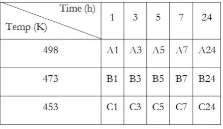
After preparation diffusion couple, specimens were heat treated in a resistive heating furnace with varying temperature and time. In this study, the two focused temperatures were 453 K, 473 K and 498 K at 5 different holding times: 1, 3, 5, 7, and 24 hours. During heat treatment, diffusion couple is loaded with 620 grams of force at all time. Heat treatment conditions are summarized in Table 1. The eutectic temperature of tin-rich composition is 490 K. The specimens that were heat treated at 498 K represented the effect of temperature above the eutectic temperature but below the melting temperature of elemental tin. The other two sets of specimens were heat treated at 453 K and 473K which were the representation of solid-state diffusion. The holding time revealed microstructure evolution and stability of each phases of Au-Sn intermetallics.
Table 1. Summary of heat treatment conditions isothermal is shown with isothermal temperatures (K) and holding times (h). There are a total of fifteen samples that underwent three isothermal treatments at varied holding time from 1 hour to 24 hours.
2.3. Characterization
[image:4.595.165.426.88.221.2] [image:4.595.188.408.498.625.2]3.
Results and Discussion
3.1. Cross-Sectional Microstructure
Diffusion couple in as-sandwiched condition is analyzed as a reference to other heat treatment conditions. The interface location and thickness were measured in order to track the interface movement and evolution. New interface between layers of gold and tin is generated and moved because diffusion rates of gold in tin and vice versa are not equal.
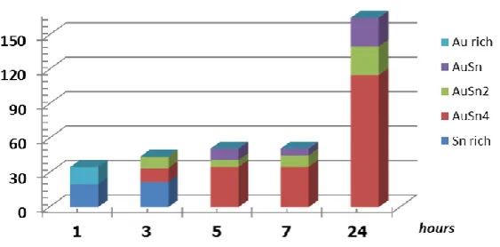
The microstructural observation for the case of 473 K and 498 K could be shown in Fig. 3 and Fig. 4. First the case of 473 K is considered in Fig. 3. The x-axis shows the time dimension of the hear treatment at 473 K while the y-axis shows the thicknesses of the IMCs and phases. The microstructures evolved from Au-rich to Sn-Au-rich, and to AuSn. Then later the formation of AuSn2 and AuSn4 followed. In particular it must be
noted that AuSn4 was later formed after 7 hours treatment time.In comparison, the case of 498 K, there is a
slight change in the IMC formation order.
For the case of 498 K, which is slightly above the eutectic temperature, the phase evolution starts with gold rich and tin rich simultaneously. This could be due to the local rejection of gold atoms from Sn-rich region of the interface because of the extremely limited solid solubility [16]. It was therefore possible to have partial melting locally or the existence of fine gold-rich precipitates inside almost pure tin matrix. AuSn4 was
then formed almost at the same time as AuSn2 while AuSn later grew.
Fig. 3. Microstructure evolution of IMCs for the case heat treatment at 473 K for 1 to 24 hours. The total thickness of the interface layer was approximately 50 micrometers after 24 hours. The phase evolution started with Au-rich, Sn-rich and then the formation of AuSn. Ultimately AuSn2 and AuSn4 formed.
[image:5.595.163.439.338.480.2] [image:5.595.160.442.553.692.2]3.2. Diffusion Assessment
To make an assessment of the diffusion kinetic, growth behavior of the intermetallic layers was studied by IMC layer thickness measurement method from previous studies [14, 17-19]. The focus is on the comparison specimens which were heat treated at 498 K and 473 K because they were comparatively close to the eutectic temperature in the Sn-rich region. The relation between IMCs layer thickness and holding time are shown for the example case of Au-Sn diffusion couple heat treated at 473 K for 24 hours in Fig. 5. As a function of position of the interface, the graph shows the mole fraction of Au to Sn ranging from 0 to 1 which is a direct indication of the types of IMCs and phases. In this case, AuSn4, AuSn2, and AuSn were the main three IMCs
located in between gold-rich and tin-rich phases. For the growth and overall length of the interface, it was clear that for the case of 473 K, Layer thickness of each IMC phase was measured from EDX line scan data and also confirmed by ImageJ software. The average thickness “li” of layer “i” was evaluated by the equation:
i i
i
A l
w
(1)
where Ai represented the total area of layer i and wi could be measured from the total length of layer i [14,
17-19]. For convenience, designation of AuSn, AuSn2, and AuSn4 IMC layers were designated with the
subscripts of i = 1,2, and 4, respectively. Moreover, the l1 and l2 were evaluated as the summation ls because
the AuSn layer did not explicitly segregate from AuSn2 layer. Furthermore, the total layer thickness l is the
summation of all IMC layers; ls and l4 because l = ls and l4. After the average thickness liof all IMC layers for
heat treated at 498 K and 473 K were obtained, n and ki values were calculated by the least-squares method
based on the following equation:
0
n
i i
l
k
t
t
(2)where t0 was unity time, 1 second and the ratio t/t0 is dimensionless [14, 17-19]. The proportional coefficient
ki has the same unit dimension as the layer thickness li. In addition, the exponent n is dimensionless. The
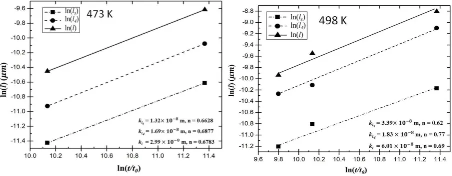
values of k and n were estimated by the least-squares method as show in Fig. 6 and Fig. 7 representing the case of 473 K and 498 K heat treatment profiles. In Fig. 6 and Fig. 7, the ordinate and the abscissa indicate the logarithm of IMCs layer thickness and the logarithm of holding time t, respectively. By assuming a monotonically increasing trend, the proportional coefficient kL and exponent n were determined to be: (a) kL
= 2.99 x 10⁻⁸ m and n = 0.68 for 473 K heat treatment, and (b) kL = 6.01 x 10⁻⁸ m and n = 0.69 for 498 K
Fig. 5. Mole fraction Au to Sn from EDX line scan is shown as a function of distance from the interfaces. Pure Sn is located at distant marker 0, while pure gold is located at the far right of the graph. There are 3 IMCs found in this case which are: AuSn4, AuSn2, and AuSn.
Fig. 6 & 7. The graphs show the values of l as a function of t/t0 through a logarithm relationship. The
values of k and n could then be obtained from the slope and the y-intersect. The graphs are the responses for the case of 473 K and 498 K for slightly below and above the eutectic temperature of tin-rich composition. The k values are shown for the case of
AuSn and AuSn
2 (kls), AuSn4(kl4) andall layers (kl).3.3. Rate-Controlling Processes
The exponent n is typically greater than 0.5. At n=0.5, the relationship is parabolic which is common for volume diffusion and diffusion controlled kinetic. In particular if the process involves a precipitation process in a primary untransformed matrix, then the relationship is usually parabolic. If n is equal to 1.0, the relationship becomes linear and the growth of the IMC is controlled by the reaction at the interface. If n value is slightly below 0.5 then grain boundary diffusion might contribute to the rate controlling process [14, 20]. In our case, the calculated n is between 0.62 - 0.77 which implies that the kinetics of IMC formations experiment are controlled by both diffusion and intermetallic reaction. Especially, at high temperature, the
[image:7.595.172.446.86.279.2] [image:7.595.73.525.342.518.2]4.
Conclusions
For heat treatment at below eutectic temperature, the IMC formation was governed by the solid-state interdiffusion of Au and Sn. The first IMC phase that formed between Au/Sn interface was AuSn. The equiatomic AuSn compound is preferred because both Sn and Au possessed similar electronic valence. Over longer period of time, as Au diffused into Sn faster, AuSn2 formed on the AuSn/Sn interface as more Au
diffused into Sn-rich region. AuSn4 was the last phase that formed on AuSn2/Sn interface.
For heat treatment at temperature slightly above the eutectic temperature, partial melting of Sn took place; consequently, Au dissolved into molten Sn-rich localized region resulting in an early formation of AuSn4
phase along with AuSn. Subsequently, AuSn2 formed between AuSn4/AuSn interface.
For industrial applications, soldering and annealing parameters are key factors leading to reliable solder joints. In real life operation, an increase in temperature with respect to time could cause the layers of different IMC phases to grow at different rates. Two distinguished mechanisms for rate controlling processes were found even if the temperature difference is only 25 K. Combined thickness of AuSn and AuSn2 phases is less
than thickness that of only AuSn4 phase. At the beginning of heat treatment, growth rate of AuSn4 was also
higher than that of either AuSn or AuSn2 . However, growth rate of AuSn4 decrease and is slower than that
of AuSn and AuSn2 after undergoing the annealing process in the range of 24 hours. Interdiffusion layers of
IMCs could be clearly observed as the specimens were heat treated for over 7 hours. Similarly, phase stability can be also seen if specimens were heat treated for longer time. AuSn, AuSn2, and AuSn4 are the IMC phases
from the Au-Sn system that were proven relatively stable at room temperature. The research work could be adapted to the soldering processes in both jewelry and electronic industries. The insights to the mechanisms suggest two possibilities for bonding process at different temperatures. For slightly above eutectic, the diffusion process is faster and preferred as the interface microstructure was uniformed and controllable. The longevity and reliability of soldered joint should also be further investigated for shearing, cyclical fatigue and failure modes.
References
[1] G. S. Matijasevic, C. C. Lee, and C. Y. Wang, “Au-Sn alloy phase diagram and properties related to its use as a bonding medium,” Thin Solid Films, vol. 223, no. 2, pp. 276-287, 1993.
[2] R. R. Chromik, D.-N. Wang, A. Shugar, L. Limata, M. R. Notis, and R. P. Vinci, “Mechanical properties of intermetallic compounds in the Au–Sn system,” Journal of Materials Research, vol. 20, no. 8, pp. 2161-2172, 2005.
[3] T. A. Tollefsen, A. Larsson, O. M. Løvvik, and K. Aasmundtveit, “Au-Sn SLID Bonding—Properties and Possibilities,” Metallurgical and Materials Transactions B, vol. 43, no. 2, pp. 397-405, 2012.
[4] C. Hillman, “Processing and reliability issues for eutectic AuSn solder joints,” in 41st International
Symposium on Microelectronics (IMAPS 2008) Proceedings, 2008, pp. 909-916.
[5] T. Tollefsen, A. Larsson, M. M. V. Taklo, A. Neels, X. Maeder, K. Høydalsvik, D. Breiby, and K. Aasmundtveit, “Au-Sn SLID bonding: A reliable HT interconnect and die attach technology,”
Metallurgical and Materials Transactions B, vol. 44, no. 2, pp. 406-413, 2013.
[6] W. Reinert and P. Merz, “Metallic alloy seal bonding,” in Handbook of Silicon Based MEMS Materials and
Technologies, Boston: William Andrew, 2010, ch. 34, pp. 533-542.
[7] M. L. Huang, Y. Liu, and J. X. Gao, “Interfacial reaction between Au and Sn films electroplated for LED bumps,” Journal of Materials Science: Materials in Electronics, vol. 22, no. 2, pp. 193-199, 2011. [8] J. W. Yoon, H. S. Chun, J. M. Koo, and S. B. Jung, “Au–Sn flip-chip solder bump for microelectronic
and optoelectronic applications,” Microsystem Technologies, vol. 13, no. 11-12, pp. 1463-1469, 2007. [9] J. W. Yoon, H. S. Chun, and S. B. Jung, “Reliability evaluation of Au–20Sn flip chip solder bump
fabricated by sequential electroplating method with Sn and Au,” Materials Science and Engineering: A, vol. 473, no. 1-2, pp. 119-125, 2008.
[10] J. Wei, “A new approach of creating Au-Sn solder bumps from electroplating,” Crystal Research and
Technology, vol. 41, no. 2, pp. 150-153, 2006.
[11] A. Dębski, W. Gąsior, Z. Moser, and R. Major, “Enthalpy of formation of intermetallic phases from the Au–Sn system,” Journal of Alloys and Compounds, vol. 491, no. 1-2, pp. 173-177, 2010.
[13] G. Elger, M. Hutter, H. Oppermann, R. Aschenbrenner, H. Reichl, and E. Jäger, “Development of an assembly process and reliability investigations for flip-chip LEDs using the AuSn soldering,” Microsystem
Technologies, vol. 7, no. 5-6, pp. 239-243, 2002.
[14] T. Yamada, K. Miura, M. Kajihara, N. Kurokawa, and K. Sakamoto, “Kinetics of reactive diffusion between Au and Sn during annealing at solid-state temperatures,” Materials Science and Engineering: A, vol. 390, no. 1-2, pp. 118-126, 2005.
[15] Y. K. Lee, Y. H. Ko, J. K. Kim, C. W. Lee, and S. Yoo, “The effect of intermetallic compound evolution on the fracture behavior of Au stud bumps joined with Sn-3.5Ag solder,” Electronic Materials Letters, vol. 9, no. 1, pp. 31-39, 2013.
[16] J. Ciulik and M. R. Notis, “The Au-Sn phase diagram,” Journal of Alloys and Compounds, vol. 191, no. 1, pp. 71-78, 1993.
[17] M. Mita, K. Miura, T. Takenaka, M. Kajihara, N. Kurokawa, and K. Sakamoto, “Effect of Ni on reactive diffusion between Au and Sn at solid-state temperatures,” Materials Science and Engineering: B, vol. 126, no. 1, pp. 37-43, 2006.
[18] T. Yamada, K. Miura, M. Kajihara, N. Kurokawa, and K. Sakamoto, “Formation of intermetallic compound layers in Sn/Au/Sn diffusion couple during annealing at 433 K,” Journal of Materials Science,
vol. 39, no. 7, pp. 2327-2334, 2004.
[19] Y. Yato and M. Kajihara, “Kinetic features of reactive diffusion between Sn-5Au alloy and Ni at solid-state temperatures,” Materials Transactions, vol. 47, no. 9, pp. 2277-2284, 2006.
![Fig. 1. Equilibrium phase diagram of binary Au-Sn alloy system (adapted from [3]). The two arrows indicate two eutectic points](https://thumb-us.123doks.com/thumbv2/123dok_us/8108698.235749/2.595.122.480.487.694/equilibrium-diagram-binary-adapted-arrows-indicate-eutectic-points.webp)