Ames Laboratory Technical Reports
Ames Laboratory
7-1960
A high-temperature vacuum extensometer
J. R. Bohn
Iowa State University
Glenn Murphy
Iowa State UniversityFollow this and additional works at:
http://lib.dr.iastate.edu/ameslab_isreports
Part of the
Chemistry Commons
This Report is brought to you for free and open access by the Ames Laboratory at Iowa State University Digital Repository. It has been accepted for inclusion in Ames Laboratory Technical Reports by an authorized administrator of Iowa State University Digital Repository. For more information, please [email protected].
Recommended Citation
A high-temperature vacuum extensometer
Abstract
An autographic extensometer for use at temperatures up to l000°C is described. Strain information is obtained from within a high vacuum enclosure by a unique application of linear variable differential transformers which provides great versatility in strain magnification and range. Important details of the vacuum test chamber and extensometer are given. Typical high temperature stress- strain records for uranium and tantalum are included to illustrate the performance of the equipment.
Disciplines Chemistry
A HIGH-TEMPERATURE VACUUM EXTENSOMETER
by
UNCLASSIFIED
IS-16 7
Chemistry-General (UC -4) TID 4500, August 1, 1959
UNITED STATES ATOMIC ENERGY COMMISSION
Research and Development Report
A HIGH-TEMPERATURE
VACUUM EXTENSOMETER
by
J. R. Bohn and Glenn Murphy
July 1960
Arne s Laboratory at
Iowa State University of Science and Technology F . H. Spedding, Director
Contract W-7405 eng-82
2 IS-167
This report is distributed according to the category Chemistry-General (UC-4) as listed in TID-4500, August 1, 1959.
Legal Notice
This report was prepared as an account of Government sponsored work.
Neither the United States, nor the Commission, nor any person acting on behalf of the Commission:
A. Makes any warranty of representation, express or implied, with
respect to the accuracy, completeness, or usefulness of the information contained in this report, or that the use of any information, apparatus, method, or process disclosed in this report may not infringe privately owned rights; or
B. Assumes any liabilities with respect to the use of, or for
damages resulting from the use of any information, apparatus,
method, or process disclosed in this report.
As used in the above, "person acting on behalf of the Commission" includes any employee or contractor of the Commission, or employee of such
contractor, to the extent that such employee or contractor of the Com-mission, or employee of such contractor prepares, disseminates, or
provides access to, any information pursuant to his employment or contract
with the Commission, or his employment with such contractor.
Printed m USA. Price
$
0 .. 50 Available from theOffice of Technical Services
U. S. Department of Commerce
ABSTRACT . • • .
INTRODUCTION .
IS-167
CONTENTS
DESCRIPTION OF THE TEST FACILITY.
TEST CHAMBER ••
EXTENSOMETER •
LOAD SENSING .
. .
. .
. . . .
.
. . . .
.
. . .
.
.
.
.
'. .
. .
.
RECORDING . . ,
PROCEDURE. .
TEST RESULTS •
CONCLUSIONS AND SUMMARY • • . . • • . • .
,
.
3Page
5
·!;)·
7
10
11
14
15
17
19
IS-167
A HIGH-TEMPERATURE VACUUM EXTENSOMETER
J. R. Bohn and Glenn Murphy
ABSTRACT
An autographic extensometer for use at
tem-peratures up to l000°C is described. Strain
infor-mation is obtained from within a high vacuum
enclo-sure by a unique application of linear variable dif-ferential transformers which provides great
versa-tility in strain magnification and range. Important
details of the vacuum test chamber and extensometer are given. Typical high temperature stress- strain
records for uranium and tantalum are included to
illustrate the performance of the equipment. INTRODUCTION
Current interest in materials for high temperature applications has
pointed out the need for a reliable means of determining high temperature tensile properties of materials. This is particularly evident when the materials to be tested do not in themselves possess the ability to
with-stand oxidation at temperatures where test information is desired. For
6
such materials contaminating environments must be prevented from coming
r l
in contact with the surface of the specimen during testing. This may be
accomplished by enclosing the specimen in a controlled environment
con-tainer; however, the effectiveness of such a method depends on the
inte-grity of the means used to transmit the necessary strain information from
within the controlled environment enclosure without interfering with the
function of the container. This presents the problem of transferring
rela-tive mechanical movement through the container walls by means of an
appropriate flexible seal arrangement. In any case, no functional
com-promise should be made between the facilities provided for strain
mea-surement and oxidation protection.
An effective method of protecting tensile creep specimens has been
developed which involves encapsulating the specimen in a flexible capsule
capable of withstanding prolonged. exposure in elevated temperature
cor-rosive conditions.* Strain measurements in this case are transmitted
through the capsule walls by means of a compound knife-edge
arrange-ment. This technique can be applied to short-time tensile testing; however,
the cost of a capsule, which is expendable, is usually unwarranted for
tests lasting only several minutes, as contrasted to long time creep testing.
* Bohn, J. R., Uhrig, R. E. and Murphy, Glenn. A method of specimen
corrosion protection for high temperature creep testing. USAEC Report
7
This investigation deals with the development of equipment arid
tech-niques for oxidation protection and strain measurements of specimens
sub-jected to short-time elevated temperature tensile tests. Test results
on uranium and tantalum demonstrate the performance of the equipment
at high temperature, vacuum and strain magnification.
DESCRIPTION OF THE TEST FACILITY
The majority of the system components used in conjunction with the
high temperature vacuum test chamber and extensometer were standard
commercial items. They included a 60, 000-lb tensile testing machine for load application, an x-y recorder for load-strain recording, vacuum
pumping and measuring devices, and temperature indicating and recording
potentiometers. Temperature control was accomplished using an
elec-tronic proportioning furnace controller designed for this specific
applica-tion, where temperature sensing for control was provided by a platinum
resistance thermometer wound integrally with the furnace heater windings.
Temperature measurements were made using chromel-alumel
thermo-couples at four points along the gage length of the specimen. A sketch
of the high temperature vacuum test chamber and extensometer is given
in Fig. 1. Figure 1 serves as schematic illustration of the functional
mechanical components of the system and also provides an index of
CUTAWAY OF FASTENER SEAL 3
EXTENSOMETER MECHANISM ROTATED 90° 14
15
I
~'-....
"1a
1917
16
5
1-1;;?---28
C'rl""'(ll)~~t----
27
- -
25
24 - - - - j
~ 3 ..
LEGEND
1. Upper cross -head fastener
2. Cross -head fastener vacuum seal
3. Cutaway of fastener seal 4. Chamber extension bellows 5. Test chamber
6. Resistance furnace
7. Specimen adaptor grip (upper) 8. Upper knife edge
9. Lower knife edge 10. Specimen grip (lower)
11. Tensile specimen
12. Tensile load rod
13. Extensometer mechanism
14. Extensometer mechanism - rotated 90
°
15. Vacuum ion gage 16. Oil diffusion pump
17. Nitrogen cooled cold trap 18. Vacuum couplings
19. Alignment bellows
20. Lower test chamber flange
21. Flexible extensometer well arrangement 22. Glass to metal vacuum coupling
23. LVDT assembly
24. Lower cross-head fastener
25. Auxiliary extensometer assembly
26. Thermocouple seal assembly 27. Gage length positioning screws 28. Gage length spacer rods
10
TEST CHAMBER
A vacuum chamber, which provides the corrosion barrier for oxidation
protection, houses the specimen and allied extensometer fixtures. The
chamber is rigidly attached to the lower load application rod which is
mounted in the lower stationary cross-head of the tensile machine. Thus,
the weight of the test chamber does not affect the tare weight of loading.
Elongation of the test chamber during loading is allowed by a bellows which
is attached to the top of the chamber and coupled to the upper cross -head
fastener and load rod through an "0" ring seal. The system is designed
to accommodate specimens of three sizes: 0. 252-in. diameter by 1. 0-in.
gage length, 0. 357-in. diameter by 1. 5-in. gage length and 0. 505-in.
dia-meter by 2.D-in. gage length. The over-all length between cross heads
is maintained constant for specimens of the various gage lengths by
chang-ing the length of the upper specimen grip. The chamber is evacuated
.th~rough an outlet in the side of the chamber which. is coupled to the vacuum
pumping system with a Genco vacuum seal. The strain and temperature
measuring fixtures located on the bottom flange of the chamber are mounted
with fittings incorporating
"0"
iing_ seals. A detachable water -cooledcoil placed around the lower chamber provides cooling for the vacuum
seals. The furnace tube portion of the test chamber is constructed of
inconel and the majority of the other components are type 316 stainless
11
The pumping system, which consists of a mechanical fore pump, an
oil diffusion pump and a nitrogen cooled cold trap, is consistently capable
of producing pressures between 1 and 5 x lo- 6 mm Hg. Pressure
mea-surements are taken in the vacuum line between the cold trap and the test
chamber. The diffusion pump and the cold trap are mounted on the vertical
support screw of the lower cross head. This mounting permits the
dif-fusion pump and cold trap to be swung out of position when not in use.
The flexible coupling in the vacuum line between the cold trap and test
chamber provides easy alignment when setting up a test. A separating
member between the cold trap and the test chamber fixes the length of
the bellows which would otherwise tend to collapse upon evacuating the
system. Figure 2 shows the apparatus less the cooling coil and cold
trap, mounted in the tensile machine.
EXTENSO METER
' .... \_
Strain measurements are transferreq through the vacuum wall of
the test chamber by a unique application of linear variable differential
transformers (LVDT) and appropriate mechanical linkages. The windings
of the LVDT are attached to the exterior of a fl'e~ible well extending thro.ugh
the bottom of the test chamber. The movable core of the LVDT is
posi-tioned on the inside of the well. With this arrangement electrical
...
N
13
by the core through the vacuum wall of the well. The voltage which is
developed in the secondary winding is proportional to the relative positions
of the core and the windings. Two extensometer wells were provided
to maintain symmetry in the forces developed by the bellows (flexible
well coupling) which are resisted by the extensorneter linkages. The
two well arrangement provides the necessary facilities for dual strain
recording applications.
Knife edges which attach directly to the specimen gage length reference
movement and provide the source of strain measurement. Movement
of the lower knife edge is transferred to the bottom flange of the
exten-someter assembly and then to the walls of the extenexten-someter well. A
bellows which is attached to the side of the well and to the bottom of the
test chamber provides flexible vacuum seal and permits the strain
initiated movement of the lower knife edge to be transmitted to the
exterior of the test chamber. This strain movement is developed between
the lower specimen grip and knife edge, a distance of about 3/8 of an inch.
The elongation of a specimen over this distance is small, imposing a
correspondingly small dimensional change in the extensometer well
bel-lows. Movement of the upper knife edge is transferred to the top and
middle flanges of the extensometer assembly, and then to the LVDT core
14
The LVDT core support rod is nonmagnetic and makes no physical
con-tact other than its point of suspension from the middle flange 6£ the
extensometer assembly.
The four· spacer rods which connect the upper and the middle flange
of the extensometer assembly can be replaced to accommodate
speci-mens of varying gage lengths. The same knife edges are used with the
0. 357 -in. diameter, 1. 5-in. gage length and the 0. 505 -in. diameter,
2. 0-in. gage length specimens by increasing the length of the spacer
rods 1/2 in. The 0. 252 -in. diameter, 1. 0 -in. gage length specimens
require a special set of knife edges. Gage length positioning screws
reference the upper and lower knife edgeclinkages at the middle
exten-someter flange in order initially to establish the exact specimen gage
length before setting the knife edges. After the gage length is established
these screws are removed. The hair··pin-shaped spring provides lateral
alignment stability of the extensometer assembly.
LOAD SENSING
An LVDT is attached directly to the load cell of the tensile machine
in parallel with the load indicator linkage. This provides the advantage
of using range and scale switching facilities built into the load indicator,
in addition to those provided in the LVDT measuring circuit.
1 ':'
15
RECORDING
A number of techniques are available for recording the ac output
voltage of an LVDT. Several of the more common methods are: (1)
di-rect ac recording with an ac potentiometer, (2) the use of specially
designed null balance type servo bridges, where the active and
compen-sating legs of the bridge are LVDT's, and (3) de recording of the rectified
output of the LVDT. In this investigation the third method was employed
since it was desired to sense both load and strain with LVDT's which
required x-y recording, thus eliminating the possibility of utilizing
method {2) which is most commonly employed in strain-recording
applications. The circuit diagram shown in Fig. 3 illustrates the
elec-trical treatment given the primary source voltage and the ac output of
the LVDT for de recording. The same circuitry is used for both strain
and load recording. Line voltage is stabilized and transformed to
pro-vide a range of 0 to 10 volts to supply the primaries of the load and
strain sensing LVDT' s in parallel. The LVDT' s used have a linear
range of 0. 125 in. on either side of null; however, the phase sensitive
rectification circuit employed eliminates the null output inherent to the
LVDT and doubles the useful range providing an output signal of a given
polarity over a range of 0. 250 in. The output signal is attenuated for
I AMP. 'o- o--<!"''...P--IAMP. ~ It AMP VARIAC M-500
+ I
~ M-500
: LOAD I L.V.D.T.
.. ________ .J
: t
+ :
: ~M-500
: STRAIN : L.V.D.T.
.. ___
_
____
....oad- straui measuring circuit
IOK.
HELIPOT Y- RECORDER
20K
RM42R
ALL 10.0.-1~
3 4 5 MV. STEPS
6 L ~STEPS
.
.,.._I
I I
a::..---·_
2.5K-1%
20K
ALL
2.5K-I%
VARIABLE
X-RECORDER
2.5K
1%
RM42R
POL. SW.
VARIABLE
'--'
17
versus magnification is linear. A maximum magnification of 2500x is
possible with an input voltage to the LVDT primary of
6.
3 volts; however,proportionately high magnifications can be obtained by increasing the
input voltage upward to 10 volts.
A bucking voltage in series with the output signal to the recorder is
provided as a means of extending the recording range. The bucking
signal is provided for both the load and strain axes and can be utilized
in two ways, continuously variable or in steps of 7. 5 mv on the x-axis
and 5 mv on the y-axis. These values correspond to full- scale
deflec-tion on the respective scales of the x-y recorder use d.
In calibration tests of the load-strain measuring system, both linearity
and stability showed deviations of less than 1% for periods less than
one-half hour. Instrument warm-up periods of at least an hour are necessary
to as sure these conditions, since temperature compensation of the
LVDT's can not be provided.
PROCEDURE
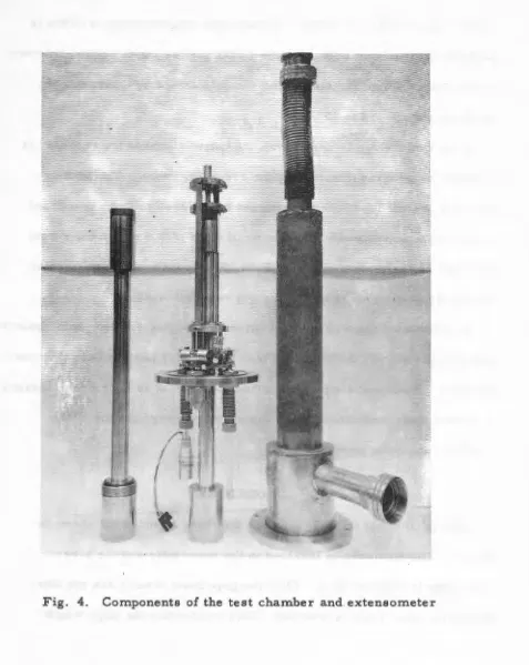
Setting up a test initially involves the three components shown in
Fig. 4. The specimen is inserted in the lower grip and the lower
knife edge is fastened to it. Then the gage point screws are set after
18
[image:21.595.56.533.71.670.2]after which the gage point set screws are removed. The four
thermo-couples are attached, the uppe:r load rod is screwed onto the specimen
and the vacuum chamber is placed over the assembly and secured to the
, bottom flange with six cap screws. Next, the seal is made between the
bellows and the upper cross -head fastener. The test chamber assembly
is now ready to be mounted in the tensile machine. The test chamber
assembly is supported in the spherical joint of the lower cross head
only which prevents the tare weight of the assembly from adding to the
load to be placed on the specimen. The remainder of the procedure is a
matter of making the necessary connections, pumping the vacuum and
establishing the desired temperature conditions. Running the test is
routine.
TEST RESULTS
19
Autographic load-strain records for uranium and tantalum have bee,n included in Figs. 5,
6
and 7 as the basis for illustrating the effectivenessof the testing apparatus. For these tests 0. 357-in. diameter, 1. 5-in.
gage length specimens were used. These specimens have a
cross-sec-tional area of 0. 10 sq. in., hence the engineering stress may be
con-veniently calculated as 10 times the load. Strain as indicated is the
total strain over the
1.
5-in. gage length; thus, unit strain ~s the total20
5
1
'13"
l
r~
~~i~-
i
~~ ~·=
--r· f'~-(1 .i:~-~ -1
E=i'd-_:c~ ::_ ---'-' -==:==-~
:::j. :J,::~.::':-: <-·-- -
=-g~;;o:~r3c:.'f::-='::-=---: ~-=-=~:i:=~
-~=:::::r:::-:.:_:=:-~::.~s
•---' ---
+---.
--i-=-:=~-=:f..;d
~¥-4
~
~~:l~-,~;2~~:~~~==:;:~~-
.
~
--~~
u.
g:gggp~
-
~
==
Yi
_-. - - - e:..cmar.
~epkek-)7~
.
~~~~;2~
~,-~~§
n
c;
~t~
~1~~
!
-F-==::;:
~ ~
-:-
_i -!
=-~~~
c
,~~-
--
~
I3
-::-
J<'~ -c:· ---~:~ -_ -c '===-t-- .-=r:
~~
-~~
~=;l~"'
-
~~ici=~::=-
"~~
-:,~
-f:
-~-,s~~~~~a~=
~
h
.
__ _,_
~S~=c~J7-p:-~n:n:-r~:--;--=
.~
RBF+
~:
i~:-~:0-~
_
:-.
_
=:-~- ~:=;=
-
~
•-
=
~~- ~7-
=f==F
~
;...
~
-:-l::= Fe.
~
-.- -- I -- - ---~a£~ci:
-x
-
H-:"-9
·
·-
=~-:~-:_:
_
-
.
·==;;
~
·
..
·
~
·
I
::
~~~}~
~
12~f~
-F~::~;
-
o
·I~
--
c
-
,,_._
'
-'
~~-~;
-
-~:~
- - :-i
=-=t-=~=
t=.=-=:=-T 8-~--::-:
-=f-·
---·!-~ +- __ ,.__
F--~~-::f=
·I=- i - -I ..:4
i -___ -;:.- =r-j _-..:-1 =i
'l _,:
t-~r::
A
~~~~:~
_~,~
-~~~--c_:~~- ~
~
-;cr,-
-
~
~~
-
-
~~l~~=
:~
~
-~ -;~
~
ij:[
t
~
-:~
'
~t!~::~
=
~~-
,
*
=
~m-
..
~~ ~~?-
~
~;?IH-
r-
i-
~
:.':- J:-~~--' =~~~----t·_-=-_:--
-=r-
-=-- __ , --~- _ " --- ~- ---~--::: _ ___,_.::_ _ - -- --=!='--~ r-- •: : ___ ! -- -1t::::'-: !---· .. - - - . - ·-- r=~ --- -
=--
i=- ::--!==== --- --~· ,-,::::.·, __ -- -- . . - -,~~.:
-,
:::
1
==:-L·:--_
-·---_J-:--:--==C!~:::=sr==.
-
~~~=- =F-=~--=
~b,_,-_:-·_=r-:>
i
-.
&
/
:
--~~~-:
__
~- ~~")[1~=:-~
____:-
.-=_;~=-
~~E- ~
~~t~~==
~:7
-
~~~~~
-:-~-~:.t::_;
_
,
.
JJ
:;
.
:-
:~~/f
_:~_~)~-~:::
--
r=
=,~=l-
=-==t~-
-
=+= -==a
-E'~~---tt
-:~~T
---~-f~-:x
-- !
~
I
j
p / 2 3 4 ~ 6 7 8 9 /0 / / /Z /3 /4 /.S
TorAL. SrR.-:vN x 10-.3 /n
Fig. 6. Load-strain curve of tantalum at 700°C
N
[image:24.591.40.763.41.564.2]-2.5/
-1- .
..
..
~~}~~-_cc~
~
~
·
~~::
~
~~~.~~;;;
~
~;::
..
. ·
.
..
I''
''
'
I
1---
-~ ;~:
·~
~,::-': ~~t~
~~:~-
~-
==:=±=-~
~
~
+~
--
~=~~: ~::.r;J~~i~~~=~
::
---
~t
~
~
-1 : _:·-:~::,=::
__
::::r-=- o:::: ,-~,~~:::E::=: - T -~.: - ~::t:_,_ __ -- -E-i:':.'k:::::i-:~-i-
'l:<<
_.:::,~'--~=--_ __;:~, ---:f -~ ~ -:,~-+-=~ £: _::~:--,:~::,:.:f:::: -=-~;_:;' ,->:k-I :
:
L ::L - - -. f. -;.· ~. ! :
-' :
<~:--
:~·::./:_~: ~;~::_
-
;~~
::-~:~: ~
~
,_=~
-~s:e:-~~;;r--:~:~~ ~~~~
:~~~;-~;-:;_;-:d~~i-
:
--
i
= L '_ =~,::'ti:..3.;_:.C::=-~~:--a:
-
-:
+ . - " - ~ · ~:-:t==:-=::;:--? ~:.- _- ;_;-.§::--:f_. ~,::---=+:,
~::L-:_,
_
I ', i ='!:=~=- -~~:::: ~"":~±~-' ___::; ~- ~ ~- "-~-:S,_ ~ -r.:.~. :~'¥- =-::~:=-:::=- -,=:=:::i:::'
:- l
-:>I:::':;': ::1~-0 - :~-' ~~: :_ct -L _t:=f.: I= ,- ~ ---=='F;:~ ~ -$' -'=f:- :==E-:: ::-"'"=:::~;:" :::.::-..:-::_r..:-'c'-::C::f'::'-E
:·
:'
I-::. i.+:;::=:f:
;
-
~
,
~
-:--: -
~~
=
~~
-
-
~
~--
._
==r-
~
--
~-
:=+==-==---~=::~::~;·-~= :r~:o
_
_
:
~~--
--
~~-'
,:~
:
.
::
_;
;• . ---·
.
:
.
\.--,;__
f
iT~f~~~·~iJ~j~~~~-::=-~-
!;~"~·
;~~~=:~i~,;~~~~···~t
j. ;
j
~
'
T
1·. · ' 1 :[:.'.:f=::":..:~-:-::":!~~~ -"E~~-
-;;.<;..
'
~
7
-
i-
.:
..:;~J.
cr):.?~7;
g
::...~-=$:1-==b-~~,g::.;:~.;;_::"c~=-=+=
:'=l _.
f - -=i~
:;••r~~·
l
'J~.
:~.·~t·~~:!::?·=
-~-··:
"
~
-~·
,
~~~
~
~:!1iz~;f:• ;~
-!···
•
·~~.
_
•
.
•.
:
•
. ·-··
·
··
]
r. ;
=t.-
! ·'
~;·~-i;;,~-=[~~~-
~=
: ___
_
=-,-~~
-~ ~
==~~~~
,7
~~~~:~~~~~~;
=r;
~
--=~~--:-,:,,
___
r-,--f-
f
~
!--H~~~
=~:~~::~-
~r~~i
:~~-
+~
--~~=
=
-
__
=~~:~~:::~'::;;~~~~:":~~~~~;
::~t
~~;~;:i:
=~-=
;
-~:T~
_;
+-
~
-
:~--:
:;-:,
,
:::,~~~,~~H::
=~
_>=
-
~
·-
_:_
~~=·~~~~~~~ ~~~.rt~
~
~~~~~ ;~:::.::-.
:-o
.
l
:;
j
'-
::;
:
:~
:::-_::~~~i:~~~t;
~
_
:==_
~
~
~
~~-;
:
:
~~~~:~;:~~~~;~~~~ ::
::~-
~t
;
:;-
<
-k
~~
;
;
=_ ,'i~-"/~_
~~~!-~ S:;~~~
~:
r +·
~~;;~~~~~-~~~
·~L
=
~
~
;.:::~
~~
·:::;::=:, :,
~
{~
,:--:_-; ,,,-,:'<~~~~--:~~~:<=-~==\:-
~-
=
;:=:~~~;~:~~~-~
::~~~~
:::.~~==c
·:_:::=l--
:
~-~
~
-f-:'
arl
;
2~--
,:,~-=- -~:~:~
.
:;
t~~
~=:=
-
~
~
f=--
7~
~~:
~~:~ ;=.~~2r::~
,
~~-::~:;_
:~_-
t·
~!
:, --Y
0 / 2 3 .4 .5 ~ 7 8 /0 / / 12 /.'f 14 IS
rorAL Sri2AtN x ;o-.3 tl?
Fig. ( .. Load-strain curve of tantalum: at 1000°C
, j ,../
N N
[image:25.591.8.738.22.558.2]abscissa are the result of expanding the strain axis, and areo::aused by
the time lapse of full scale pen travel. Recording was terminated as
indi-cated by the notation, "extensometer disengaged". Disengagerr:e nt of the
extensometer occurs when necking-down of the specimen causes uncoupling
of the knife edges.
CONCLUSIONS AND SUMMARY
The elastic properties of materials do not adequately describe the
stress-strain properties of materials which behave in a semi-plastic
manner. In elevated temperature applications it is particularly desirable
to have available the actual stress-strain records for the material.
Re-producible autographic recordings greatly simplifies such a task.
The performance of the test equipment described is considered
ex-cellent for intended applications. It is believed that testing at
tempera-tures greater than l000°C could be achieved by improving the materials
of construction and providing the heat from within the vacuum chamber.
Strain magnifications up to 3000 are possible over a range of 0. 250 in.
High magnification and extended range provides great versatility for
most stress -strain applications. In addition, the provisions for dual
strain sensing provides the advantage of dual range recording. One
24
greatly magnify a portion of the stress-strain curve of particular interest.
Another outstanding feature of the strain measuring apparatus is its
ability to give a continuous record to fracture without necessitating