A Novel Interplanetary Communications Relay
Robert J. McKay1, Malcolm Macdonald2
Advanced Space Concepts Laboratory, University of Strathclyde, Glasgow G1 1XJ, United Kingdom
Massimiliano Vasile3
Space Advanced Research Team, University of Glasgow, Glasgow G21 8QQ, United Kingdom
Francois Bosquillon de Frescheville4
European Space Operations Centre, European Space Agency, 64293 Darmstadt, Germany
A case study of a potential Earth-Mars interplanetary communications relay, designed to ensure continuous communications, is detailed. The relay makes use of orbits based on artificial equilibrium points via the application of continuous low thrust, which allows a spacecraft to hover above the orbital plane of Mars and thus ensure communications when the planet is occulted with respect to the Earth. The artificial equilibria of two different low-thrust propulsion technologies are considered: solar electric propulsion, and a solar sail/solar electric propulsion hybrid. In the latter case it is shown that the combination of sail and solar electric propulsion may prove advantageous, but only under specific circumstances of the relay architecture suggested. The study takes into account factors such as the spacecraft’s power requirements and communications band utilized to determine the mission and system architecture. A detailed contingency analysis is considered for recovering the relay after increasing periods of spacecraft motor failure, and combined with a consideration for how best to deploy the relay spacecraft to maximise propellant reserves and mission duration.
Nomenclature
𝐴𝑆 sail area (not including thin film solar array area)
𝐴𝑇𝐹 thin film area
𝐴𝑇 total hybrid sail area, = 𝐴𝑆+ 𝐴𝑇𝐹
𝑎𝑟𝑒𝑓 dimensional reference acceleration, equal to unit sail lightness number = 5.93 mms-2
𝒂𝑔𝑐 nondimensional required acceleration vector to balance gravitational and centrifugal force
𝑎𝑠 nondimensional acceleration magnitude due to solar radiation pressure
𝒂𝑠 nondimensional acceleration due to solar radiation pressure
𝒂𝑆𝐸𝑃 nondimensional acceleration due to SEP thruster
1
Research Fellow, Advanced Space Concepts Laboratory, University of Strathclyde, Glasgow, UK. 2
Associate Director, Advanced Space Concepts Laboratory, University of Strathclyde, Glasgow, UK, AIAA Associate Fellow.
3
Senior Lecturer, Space Advanced Research Team, University of Glasgow, Glasgow, UK. 4
𝑎𝑇 nondimensional thrust acceleration from electric propulsion system of hybrid sail
𝒂𝑔𝑐 nondimensional acceleration required to balance gravitational and centrifugal
𝐼𝑆𝑃 specific impulse
m spacecraft mass
𝑚0 initial mass of hybrid sail
𝒏 thrust vector orientation
𝒓, r position vector with respect to centre of mass of primaries, orbit radius
𝑟 𝑆 solar sail film reflectivity
𝑟 𝑇𝐹 thin film solar array reflectivity
T continuous and constant low thrust
𝑣 centripetal potential
𝑽 augmented potential
𝛼 pitch angle
𝛽0 solar sail lightness number
𝜆 ratio of 𝒂
to
∇𝑽𝛿 solar sail clock angle
𝛿 clock angle of vector 𝒂𝑔𝑐
𝜃 solar sail cone angle
𝜃 cone angle of vector 𝒂𝑔𝑐
𝜇 reduced mass gravitational parameter
𝝎 orbital angular velocity
𝜎∗ critical solar sail loading parameter, = 1.53 × 10⁻³ kg m-2
1 - Introduction
he concept of counter-acting gravity through a thrust vector was apparently first proposed by Dusek in 1966,
who noted that a spacecraft could be held in an artificial equilibrium at a location some distance from a natural
libration point if the difference in gravitation and centripetal force (gravity gradient) were compensated for by
continuous low thrust propulsion [1]. More recently, this concept has been explored for the special case of solar sail
propelled spacecraft which can, in principle, generate continuous thrust without the need for reaction mass [2]. A
generic continuous thrust can be applied in all directions including perpendicular to the flight direction, which forces
the spacecraft out of a natural orbit into a displaced, non-Keplerian orbit: such orbits could have a diverse range of potential applications. Forward coined the term “statite” [3] in reference to a mission using a solar sail to hover
above, or below, the Earth in such a displaced orbit in a concept which has evolved to become known as the Polar
Observer, or PoleSitter, mission [4]. Following the work of Forward, McInnes made an extensive study of the
concept [4], exploring new regions of interest, including the study of artificial, or displaced, Lagrange points which was considered extensively in the late 1990’s under the NASA/JPL/NOAA GeoStorm mission concept [5,6].
The initial work led by McInnes has since been evolved by others to consider different forms of propulsion, such as
solar electric propulsion (SEP) [7,8]. Such work has focused primarily on Earth-centred trajectories, although some
authors have considered individual applications of non-Keplerian orbits outwith the Earth’s influence - for example,
for in-situ observation of Saturn’s rings [9]. This prompted McKay et al. to extend the work of McInnes for celestial
bodies other than just the Earth, and systematically catalogue non-Keplerian orbit regions throughout the solar
system [10].
In doing so, Ref. [10] highlighted the possibility of using such orbits for a potential Earth-Mars communications
relay, not dissimilar in concept to that proposed for lunar communications by Wawrzyniak & Howell [11]. For any
future manned exploration of Mars, continuous communication between the surfaces of the two planets will be
required. Currently, during periods of solar occultation assets both in-orbits about Mars and on its surface are out of
communication with ground controllers. While such a scenario is undesirable for robotic assets it is acceptable.
However, this is not so for human exploration. Therefore, a communication relay is required to ensure continuous
communication between Earth and Mars. To address this issue non-Keplerian orbits outwith the orbital plane of
Mars were considered in Ref. [10], and expanded upon here. Indeed, it is noted that any spacecraft within, or even
which passes through, the orbital plane of a planet in the solar system shall experience periods of solar occultation of
Earth, and thus the problem is more generic than the specific case of Mars.
2 - Highly Non-Keplerian orbit model and definition
Following McInnes [12], the conditions for circular displaced highly non-Keplerian orbits can be investigated by
considering the dynamics of a spacecraft of mass 𝑚 in a reference frame 𝑹(𝑥, 𝑦, 𝑧) rotating at constant angular
velocity 𝝎 relative to an inertial frame 𝑰(𝑋, 𝑌, 𝑍). With such a system the equations of motion of the
spacecraft are given by,
where 𝒓 is the position vector of the spacecraft, dots denote differentiation with respect to time 𝑡,and 𝑽and 𝒂 are
the augmented potential and the continuous and constant acceleration due to the propulsion system respectively, the
former being given by,
𝑽 = −
1 − 𝜇
𝒓
1+
𝜇
𝒓
2+
1
2
𝝎 × 𝒓
2
(2)
in units where the gravitational constant 𝐺 = 1 and the system has total unit mass, and where 𝜇is the reduced mass,
𝜇 =
𝑚
1𝑚
1+ 𝑚
2(3)
and the latter being given by,
𝒂 =
𝑇
𝑚
𝒏
(4)
where 𝒏 is the direction of the thrust 𝑇 (where this equation makes no assumption about the propulsion system used,
so for e.g. a solar sail Equation (4) must be modified accordingly). By setting 𝒓 = 𝒓 = 0,i.e. assuming equilibrium
conditions in the rotating frame, then the equation 𝛻𝑽 = 𝒂 defines a surface of equilibrium points. Further, the
required thrust vector orientation for an equilibrium solution is then given by,
𝒏 =
∇𝑽
∇𝑽
(5)
and the magnitude of the thrust vector, 𝒂 , is given by,
𝒂 = ∇𝑽 .
(6)
Equation (6) provides a simple definition of what constitutes a non-Keplerian orbit. Defining a parameter 𝜆 such
that,
𝜆 =
𝒂
∇𝑽
the specific case of highly non-Keplerian orbits can be considered: that is, when 𝜆 ≅ 1, or, equivalently, when the
acceleration applied by the low-thrust propulsion system is of approximately the same order as the gravitational
acceleration experienced by the spacecraft. For comparison, orbits with 𝜆 = 0 represent ideal Keplerian orbits, in
essence the large subset of classical celestial orbital mechanics without the addition of a non-conservative force.
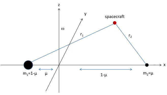
McKay et al. [13] carried out a detailed study of artificial equilibrium points and surfaces throughout the solar
system, formulating the equilibrium points in the circular restricted three-body problem (CRTBP). This was done by
considering the dynamics of a spacecraft of mass 𝑚 in a rotating reference frame in which the primary masses 𝑚1
and 𝑚2 are fixed in the rotating frame (as shown in Figure 1), or, equivalently, in the inertial frame they orbit
circularly with constant angular velocity 𝜔 in the ecliptic plane about their common centre of mass. If the unit of
length of the system is chosen such that the distance 𝑅 between the primary masses is unity, and with 𝐺 = 1 and
reduced mass as defined by Equation (3), then the nondimensional unit acceleration of the system is given by
𝑎𝑟𝑒𝑓 = 𝜔2𝑅. In Figure 1 the 𝑥-axis points between the primary masses, the 𝑦-axis denotes the axis of rotation and
the 𝑧-axis is orthogonal to both.
r2
spacecraft
r1
m2=µ
m1=1-µ µ 1-µ
x y
z
[image:5.612.142.470.333.521.2]
Fig. 1: The rotating coordinate frame and the spacecraft position therein for the restricted three-body problem.
The position vectors 𝒓1 and 𝒓2 of the spacecraft with respect to the primary masses 𝑚1 and 𝑚2 are then given by
𝒓1= 𝑥 + 𝜇, 𝑦, 𝑧 𝑇 and 𝒓
2= 𝑥 − 1 − 𝜇 , 𝑦, 𝑧 𝑇
respectively, where the equations of motion, augmented
potential and reduced mass of the system are as previously given by Equations (1-3). The equation for the magnitude
of the acceleration vector 𝒂 as given by Equation (6) then defines an implicit function in the rotating coordinates.
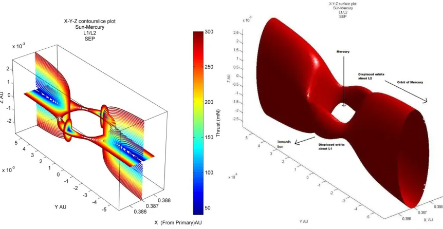
As an implicit function can be expressed in the form 𝑓 𝑥, 𝑦, 𝑧 = 0 it defines a three-dimensional equithrust surface
(or, equivalently, two-dimensional equithrust contours) which can be plotted, as illustrated in Figure 2 for the
Anywhere on this equithrust surface, a spacecraft with the required thrust, oriented in the direction needed, will
therefore exist in equilibrium with the body in question. With such a formulation then a spacecraft occupying a
given artificial Lagrange point on this surface tracks out a circular periodic orbit in the inertial reference frame, with
the period being defined by that of the body which the spacecraft is in equilibrium with.
Fig. 2: Artificial equilibrium points depicted by equithrust contours projected onto the planes perpendicular to and parallel to the orbital plane (left), and the 300mN equithrust surface (right) for the Sun-Mercury L1/L2
system.
3 – Communication Relay Architecture Options
3.1 Overview
As referred to previously, McKay and co-workers [10] outlined a concept for an Earth-Mars communications
relay that uses non-Keplerian orbits to hover above the orbital plane of Mars in order to relay signals between the
two bodies during periods of occultation by the Sun, and thus ensure continuous communications between Earth and
assets on the surface of Mars. Here that work is recapped briefly, prior to expanding upon it in the following
sections.
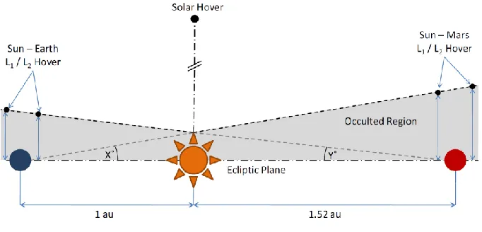
Figure 3 provides a schematic diagram of such a relay, where the angle X represents the field-of-view exclusion
[image:6.612.77.508.191.414.2]Fig. 3: Earth-Mars communication relay architecture options out of the orbital plane.
The technology requirements of such an array are largely determined by the field-of-view exclusion zone about the
Sun, which is dependent on how close to the limb of the Sun radio signals can be transmitted without interference
from the solar plasma. For design optimization purposes a spacecraft in proximity of Mars is preferred as the long
slant range back to Earth can be compensated for through the use of a large Earth-based antenna.
If a 4-degree field-of-view exclusion of Mars from Earth is assumed (a realistic value if assuming communications
in the X-band portion of the electromagnetic spectrum), the Sun – Mars stations can be determined to be located
approximately 0.176AU out of the orbital plane, while the Sun – Earth stations can be determined to be located
approximately 0.116AU outwith the orbital plane (since the equivalent spacecraft-Mars-Sun angle is then 2.64°).
The much shallower gravitational potential well at Mars significantly increases the distance from the planet that a
spacecraft can hover at in comparison to Earth. Naturally, different EM communication bands, such as Ka-band,
define different field-of-view exclusion angles – this point will be returned to in the next subsection.
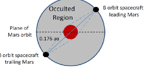
An interesting extension to this concept is to consider spacecraft in displaced orbits either leading or trailing the
orbit of Mars, i.e. in the orbital plane. Considering the symmetry of Figure 3, the field-of-view exclusion defines a
conic region around the Sun where Mars is hidden from the Earth. If this conic region is considered end-on from
behind Mars, as shown in Figure 4, as well as achieving continuous communications by displacing a spacecraft
directly above Mars, a spacecraft could also be displaced onto the circular (when projected in two dimensions)
region around Mars defined by the field-of-view exclusion, so that one spacecraft was trailing and the other leading
Figure 4: End-on view of an alternative Mars-Earth communication relay architecture option, looking along the orbital plane.
Naturally, as they track Mars they too will enter the blackout region: as depicted in Figure 4, the leading spacecraft
will move beyond the edge of the blackout region as the trailing spacecraft moves into this region. However, the
separation of the two spacecraft means that only one will ever be in this region at any given time, and, given the
distance between the spacecraft, the arc of the orbit is easily sufficient to maintain a line-of-sight between the two
spacecraft (i.e. one will not be occulted by Mars with respect to the other), allowing continual communications to
still be achieved by relaying the signal from the occulted spacecraft to the one outside the occulted region and then
on to Earth.
Positioning of the spacecraft then depends on what is required from the mission. The relay spacecraft will need less
thrust to maintain their position with respect to Mars if they are not displaced out of the orbital plane, but that would
only allow for communication with assets near the equator of the planet. To communicate with assets at higher
latitudes it will be necessary to displace the spacecraft out of the orbital plane, which requires more thrust.
3.2 Solar electric propulsion
Having outlined the concept of the relay in the previous subsection, the amount of thrust required in order to occupy
some potential hover points to enable the relay is quantified. To do this a spacecraft of total mass 1000kg is
assumed, with a solar electric propulsion (SEP) thruster with a maximum thrust of 300mN and a specific impulse
(ISP) of 4500 seconds. These assumptions allow for a consideration of opportunities based on current or near-term
SEP technology such as the Qinetiq T6 thruster, which will theoretically provide a thrust of up to 230mN at an ISP of
above 4500 seconds for the BepiColombo mission [14], although such capabilities still have to be demonstrated
within the context of any space mission.
Considering first of all the non-Keplerian orbit regions displaced out of the orbital plane, as illustrated in Figure 5, it
can be seen that the 300mN thrust is sufficient to displace the spacecraft 0.176AU directly above Mars, which, from
the previous section, is just enough to ensure that the spacecraft could communicate with Earth, assuming a 4 degree
Figure 5: Non-Keplerian orbit contours at Mars in the plane displaced out of the orbital plane, for a 1000kg solar electric propulsion (SEP) spacecraft with 300mN maximum thrust. The arrows indicate the required
thrust orientation for the artificial equilibrium point.
However, there are some advantages to considering the dual spacecraft option discussed in the previous subsection,
over the case of a single spacecraft hover. Firstly, hovering directly above Mars limits communications to just the
polar region. If the spacecraft are trailing or leading the orbit then communication with the equatorial regions is
enabled, with the ability to cover most of both hemispheres of Mars. A more important advantage can be shown by
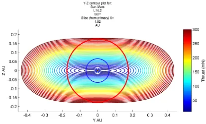
Figure 6: An end-on view of non-Keplerian orbits depicted by equithrust contours, for a 1000kg SEP spacecraft with 300mN maximum thrust about Mars, looking along the orbital plane. The red and blue
circles indicate the field-of-view exclusion zone for X-band and Ka-band communication respectively.
As can be seen it is much easier to displace the spacecraft orbit from Mars in this plane (i.e. along y) than out of it (i.e. along z) and so a spacecraft can occupy a non-Keplerian orbit on the surface defined by the field-of-view exclusion for less thrust if it trails or leads Mars rather than hovering directly above. For example, displacing the
spacecraft 45 degrees out of the orbital plane of Mars would reduce the thrust requirements to approximately
200mN, assuming the 4 degree field-of-view exclusion defined by X-band communication. So, practically, it may be
more feasible to maintain the communications relay using two spacecraft with lower thrust than a single spacecraft
which needs higher thrust.
This is true for the case of a 4 degree field of view exclusion of Mars from Earth by the Sun, which is a realistic
value if it is assumed that the communication relay is via the X-band portion of the electromagnetic spectrum. If
instead the use of Ka-band is considered, the field of view exclusion can be reduced to just 1.5 degrees (as shown
via the blue circle in Figure 6), with signals in this frequency range being less affected by the solar plasma. This
obviously reduces the thrust requirements for the relay spacecraft considerably: it would then need to hover 9.872
million km (0.066 AU) directly above Mars, which could be done for a one tonne spacecraft with approximately
110mN of thrust, or there could be two spacecraft (one leading and one trailing the orbit of Mars, as in Figure 22) displaced 45 degrees out of the orbital plane (6.98 million km above Mars’ orbital plane), which would require just
80mN of thrust each. Ka-band would be preferable for many other reasons, for example the higher bandwidth and
thus data rate that comes with it, and the lower power requirements for the antenna, but Ka-band communication is
option. However, NASA is already beginning the process of transitioning to Ka-band (because X-band is too narrow
to support future high data rate missions), with the Mars Reconnaissance Orbiter being equipped with a fully
functioning Ka-band communications suite [15].
One should also consider that the non-Keplerian orbit actually need only be maintained during periods of solar
occultation, and hence it may be possible to extend the spacecraft lifetime by only using the thrusters to provide
significant amounts of thrust during such periods and allowing the spacecraft to follow a conventional
near-Keplerian orbit during other periods. For example, the synodic period of Mars (the temporal interval that it takes for
an object to reappear at the same point in relation to two other objects) with respect to Earth and the Sun (and thus
the occultation repeat period) is approximately 780 days, whereas the sidereal period (the temporal interval it takes
an object to make one full orbit around the sun) is roughly 687 days. Thus one could envisage a mission that would
see the SEP spacecraft thrusting to hover above Mars for 93 days to maintain communications whilst Mars is
occulted, and then, when Mars is no longer occulted, using the thruster efficiently to re-acquire the relevant artificial
equilibrium point (AEP) via a pre-planned orbital maneuver, returning to the correct point for the next occultation of
Mars (where the thruster would be switched back on to occupy the non-Keplerian orbit position again). Thus the
craft would only need to continually thrust at the levels outlined in the previous two paragraphs for about 90 days in
every 2.13-year period (approximately) as opposed to the entire time, which would significantly extend the
on-station time as allowed by the thruster propellant reserves. Consideration of such maneuvers is returned to in Section
4.2.
Finally, it is worth considering the advantages of such a communications relay architecture option, over some of the more obvious potential setups. One might instead consider a relay consisting of a spacecraft at Earth’s L4/L5 point,
or likewise at Mars’ L4/L5 point. The former case of an Earth-Earth L5-Mars relay then requires that a signal be sent
over a total distance of approximately 3.21AU, with a distance of about 2.21AU between Mars and the relay
spacecraft. The latter case of an Earth-Mars L4-Mars relay spans a distance of approximately 3.73AU, with a
distance between Mars and the relay space of around 1.52AU. Compare these numbers with the architecture as
suggested above, with a relay spacecraft about 0.18AU from Mars and a total relay distance of around 2.7, meaning
that the non-Keplerian orbit allows a relay station that spans a considerably smaller distance than using conventional
Lagrange points, and enables a considerably higher data rate between the surface of Mars and the relay spacecraft.
3.3 Hybrid Solar Electric Propulsion / Solar Sail
Both SEP and solar sail low thrust propulsion systems have their own advantages and disadvantages. Solar sailing
has the advantage of an effectively infinite specific impulse, i.e. requires no propellant/fuel, and thus can maintain
continuous low thrust indefinitely (in theory, at least – in practice, long-term degradation of the optical surface may
reduce the efficiency of the sail and propellant may be required for attitude control). However with SEP the thrust
can be oriented in any direction, allowing access to artificial equilibria that a solar sail would be forbidden from with
device that would combine the best features of both systems, to obtain a hybrid sail: indeed, it has recently been
suggested that such an approach may, in recognition of the high Advancement Degree of Difficulty of solar sailing,
be the best means of advancing solar sail technology [16]. Such an idea has been considered in the literature
previously – see, e.g. Leipold & Götz [17] and Mengali & Quarta [18], with the latter showing that hybrid sails
have the attractive feature of reducing mission times for heliocentric transfers when compared to both the equivalent
pure sail and pure SEP trajectories. Recently Baig & McInnes [19], Simo & McInnes [20] and Ceriotti & McInnes
[21] have all considered the case of displaced highly non-Keplerian orbits for the specific situation of a hybrid sail.
The analysis of Ref. [19] is followed by considering a partially reflecting hybrid sail consisting of an SEP thruster
attached to the centre of a solar sail (as shown in Figure 7), a model adapted from that of Leipold & Götz [17]. The
solar sail is taken to be square, with part of the sail area at the centre of the sail covered by flexible thin film solar
[image:12.612.166.450.311.459.2]cells (TFSC), which act as a power source for the SEP system.
Fig. 7: Specularly reflecting hybrid sail solar radiation pressure force model.
In this model, 𝒏 and 𝒕 are the unit vectors normal to and transverse to the hybrid sail surface, respectively, 𝒓 1 is the
direction of incident photons, and the unit vector 𝐬 defines the direction of specularly-reflected photons. With such a
model the total thrust of the hybrid sail due to both solar radiation pressure and solar electric propulsion is given by
[19]
𝐅
𝑇𝑜𝑡= 𝐅
𝑆𝐸𝑃+ 𝐅
𝑆𝑎𝑖𝑙= 𝐹
𝑛𝒏 + 𝐹
𝑡𝒕 + 𝑇𝒖
(8)
where 𝐹𝑛 and 𝐹𝑡 denote the forces normal to and transverse to the sail respectively, and 𝑇 denotes the thrust from the
SEP, where the unit vector 𝒖 denotes the thrust direction. Expressions for 𝐹𝑛 and 𝐹𝑡 can be derived via consideration
of the projected area of the hybrid sail in the direction of the incident photons, and shown to be, respectively,
and
𝐹
𝑡= 𝒓
1∙ 𝒏
2𝒓
1
∙ 𝒕 1 − 𝑟
𝑆𝑃𝐴
𝑆+ 1 − 𝑟
𝑇𝐹𝑃𝐴
𝑇𝐹(10)
where 𝑟 𝑆 and 𝐴𝑆 is the sail reflectivity and sail area, and 𝑟 𝑇𝐹 and 𝐴𝑇𝐹 are the TFSC reflectivity and area.
Using Equation (8), expressions for both the nondimensional acceleration 𝒂𝑠 due to the solar radiation pressure
acting on the sail, and the nondimensional acceleration 𝒂𝑆𝐸𝑃 due to the SEP thruster, can be derived by dividing by
mass 𝑚 and dimensional reference acceleration 𝑎𝑟𝑒𝑓 = 𝜔2𝑅 (where 𝑅 is the distance between the primary bodies) to
give, respectively,
𝒂
𝑠= 𝒂
𝑠𝒎 =
12
𝛽
0 𝑚0𝑚 1−𝜇
𝑟12
𝑔 𝒓
1∙ 𝒏
2
𝒏 +
12
𝛽
0 𝑚0𝑚 1−𝜇
𝑟12
𝒓
1∙ 𝒏 𝒓
1∙ 𝒕 𝒕
(11)
and
𝒂
𝑆𝐸𝑃=
𝑇/𝑚𝑎𝑟𝑒𝑓
𝒖 = 𝑎
𝑇𝒖
.
(12)
Equation (11) has magnitude as determined by
𝑎
𝑠=
1 2𝛽
0𝑚0
𝑚 1−𝜇
𝑟12
𝑔
2
𝑐𝑜𝑠
2𝛼 +
2𝑠𝑖𝑛
2𝛼 cos 𝛼
(13)
where the parameters 𝑔 and are given by
𝑔 = 1 + 𝑟
𝑆−
𝐴𝑇𝐹𝐴𝑇
𝑟
𝑆− 𝑟
𝑇𝐹(14)
= 1 − 𝑟
𝑆+
𝐴𝑇𝐹𝐴𝑇
𝑟
𝑆− 𝑟
𝑇𝐹(15)
and 𝑚0 is the initial mass of the hybrid sail, 𝛼 is the sail pitch angle, and 𝛽0≡ 𝜎∗/(𝑚0/𝐴𝑇) is the sail dimensionless
lightness number, where 𝜎∗ is the critical sail loading parameter of 1.53 × 10⁻³ kg m-2 .
∇𝑉 𝒓
𝟎= 𝒂
𝑆+ 𝒂
𝑆𝐸𝑃≜ 𝒂
𝑔𝑐(16)
i.e. ∇𝑉 𝒓𝟎 = 𝒂𝑔𝑐 is the acceleration vector required to cancel the gravitational forces of the two primary masses
and the centrifugal force in the rotating reference frame, a vector which can be achieved with a hybrid sail through
the vector sum of the solar radiation pressure and SEP acceleration vectors.
The work of Ref. [19] is followed in defining a new reference frame that has its origin at the hybrid sail position and
has a set of three orthogonal vectors 𝒓1 , 𝜔 × 𝒓1, 𝒓1× 𝜔 × 𝒓1 . By making this frame transformation, the low
thrust acceleration from the SEP system of the hybrid sail can be expressed in terms of the sail pitch and clock
angles and 𝛼 and 𝛿 respectively, giving
𝑎
𝑇2𝛼, 𝛿
=
𝑎
𝑔𝑐2− 2𝑎
𝑔𝑐𝑎
𝑠cos 𝜃 cos 𝜃 + sin 𝜃 sin 𝜃 cos 𝛿 − 𝛿 + 𝑎
𝑠2(17)
where (see Ref. [19] for a fuller derivation) 𝜃 and 𝛿 are the cone and clock angles of the vector 𝒂𝑔𝑐 (and depend
upon the artificial equilibrium point 𝒓0) and the cone angle of the hybrid sail is given by
tan 𝜃 =
𝑔 − tan 𝛼
𝑔 + 𝑡𝑎𝑛
2𝛼
(18)
It can then be shown that the hybrid sail clock angle should be aligned with the clock angle of the vector 𝒂𝑔𝑐 in
order to obtain the maximum benefit from the solar sail [19], that is,
𝛿 = 𝛿 . (19)
Considering the hybrid sail at time 𝑡 = 0, 𝑚 = 𝑚0 and from Equation (11) it is possible to orient the solar radiation
pressure acceleration vector in order to obtain all or at least part of the acceleration vector 𝒂𝑔𝑐 required to occupy an
artificial equilibrium point 𝒓0, since, for a pure solar sail or pure SEP system the required acceleration magnitude
and thrust orientation are completely defined by the location of the artificial equilibrium point. Baig & McInnes [19]
proceed by selecting this optimum orientation to obtain the maximum benefit from the solar sail, and then use this
acceleration to minimize the SEP thrust to achieve the desired vector 𝒂𝑔𝑐. Here, though, instead it is assumed that
the thrust from the SEP system is fixed in the direction required for a given artificial equilibrium point, and added to
that is the magnitude of the acceleration from the solar sail oriented to give the maximum benefit. This in effect
opens up a greater volume of space that the hybrid sail can occupy over the pure SEP, pure sail, and Baig &
McInnes SEP thrust-minimized hybrid systems, thus allowing a determination if there are artificial equilibria that
sail is effective, we have a greater magnitude of acceleration available for the hybrid solar sail/SEP spacecraft,
which allows access to artificial equilibrium points that would otherwise be beyond the capabilities of the pure SEP
system with thrust equal to that of the SEP part of the hybrid SEP/solar sail spacecraft.
With this in mind the analysis considered for a pure-SEP system, in determining the non-Keplerian orbit equithrust
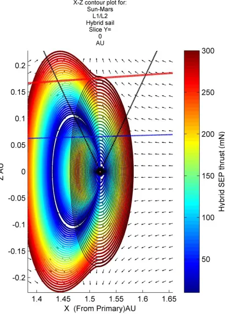
contours at Mars, can be repeated for the hybrid sail. Figure 8 shows the contours for orbits displaced out of the
orbital plane for a hybrid spacecraft with a solar sail of characteristic acceleration 0.2 mms-2 (equivalently, sail beta
of 0.034) and sail reflectivity 0.9. The sail area is 45m × 45m = 2025 m2, giving a sail loading of 45.63 gm-2. The
TFSC reflectivity is taken to be 0.4 and the TFSC area is assumed as 12 m2 purely for the sake of example. This sail
is assumed to be attached to the usual 1000kg SEP-propelled spacecraft capable of a maximum thrust of 300mN, as
assumed previously. The pure-SEP contours of equivalent SEP thrust (i.e. not total acceleration/thrust) are overlaid in thin black lines, in order to compare the region of non-Keplerian orbits, and the arrows represent the direction of
the vector 𝒂𝑔𝑐 required to occupy a given artificial equilibrium point.
Fig. 8: Non-Keplerian orbit equithrust contours at Mars, projected onto the plane perpendicular to the orbital plane, for a hybrid sail with characteristic acceleration 0.2 mms-2 and other parameters as given in the
text. The black contours represent the contours for an equivalent pure-SEP system.
It is clear to see from Figure 8 that adding a solar sail to the SEP spacecraft allows access to a greater volume of
the day-side of the planet around L1 and a small increase on the night-side of the planet around L2 (which is hard to
see given the scale of this particular plot but will be more obvious in subsequent plots, particularly Figures 12 and
13). This non-symmetry is to be expected, given the regions of non-Keplerian orbits the pure sail can access. It is
also clear that the addition of the solar sail does not allow the hybrid to be displaced any further out of the orbital
plane for the same amount of thrust, and thus in the context of the Earth-Mars communication relay as described
previously this is perhaps a disappointing result. However, deeper consideration of the solar sail reveals why both of
these points are indeed the case.
Firstly, consider the artificial equilibrium solutions for the solar sail itself. McInnes [22] considered the equilibrium
solutions for a non-perfect solar sail, which is of importance because, aside from reducing the magnitude of the solar
radiation pressure exerted on the sail surface, the partial reflectivity and hence finite absorption means that the
radiation pressure force vector is no longer normal to the sail surface, and thus the equilibrium surfaces and
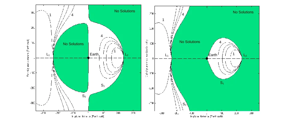
accessible regions are slightly different, as compared in Figure 9.
Earth
L1 L2
1 4
4 1 No Solutions No Solutions S1 S2 Earth
L1 L2
[image:16.612.72.535.311.506.2]1 4 4 1 No Solutions No Solutions S1 S2
Fig. 9: Comparison of contours of sail loading in the x-z plane with reflectivity 𝜼 = 𝟏 (left) and 𝜼 = 𝟎. 𝟗
(right), where the contours are, in gm-2: [1] 30 [2] 15 [3] 10 [4] 5.
For a non-perfect reflectivity, it can be seen that there are no regions of possible solution directly above the planet
(in this instance, the Earth, but the principle is the same for Mars). Thus it is impossible to have a solar sail stationed
at a hover point directly above the planet. Even regardless of the reflectivity it can be seen that this is effectively the
case: for a perfectly reflecting sail there is a region of singularity above the Earth where a sail would have to have
effectively infinite acceleration in order to occupy such a spot. Bearing Figure 9 in mind it is not surprising,
therefore, that the hybrid sail shows no advantage over the pure SEP system for non-Keplerian orbits displaced
Regardless, the fact that there is no advantage in using a hybrid to hover directly above Mars does not in itself rule
out the possibility of a hybrid system being potentially more useful than SEP alone as part of such a communications
relay. Hovering directly above Mars is not exactly the same as a polesitter spacecraft, i.e. a spacecraft constantly
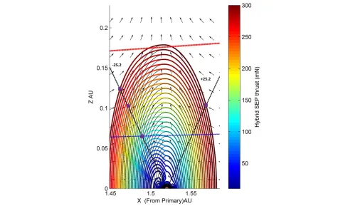
aligned with the polar axis of the Earth, because of the tilt of that axis. Replotting Figure 8 to illustrate the ±25.2º
axial tilt of Mars, as shown in Figure 10, four specific points are highlighted in purple which illustrate where the
spacecraft can be stationed such that they are directly above the pole of Mars. Three of these points are on the
day-side of Mars, with coordinates of (1.462, 0.125), (1.472, 0.103) and (1.490, 0.065) respectively, in AU. The first two
points show that the addition of the solar sail component of the hybrid extends the distance the spacecraft can hover
directly above the pole at the summer solstice from 0.114AU to 0.137AU (i.e. can now station at the former point as
opposed to the latter), or, equivalently, to occupy the latter point the hybrid spacecraft needs a thrust of only 240mN
from the SEP component, compared to the 300mN required for a pure-SEP spacecraft. The third point shows the
minimum distance required to complete the communications relay in Ka-band, which requires approximately
130mN from the hybrid SEP and 190mN from the pure-SEP. The fourth point on the night-side of the planet shows
[image:17.612.63.538.320.609.2]that having the sail is of no additional benefit here.
Fig. 10: Non-Keplerian orbit equithrust contours at Mars, projected onto the plane perpendicular to the orbital plane, for the hybrid sail as plotted in Figure 8. The black contours represent the contours for an equivalent pure-SEP system, and -/+25.2° are the angles of the polar axis of Mars, denoted by dashed lines, with respect to the normal to the orbital plane at the summer and winter solstices respectively. The red and
Thus it can be seen that the addition of the sail can reduce the SEP requirements to hover directly above the pole of
Mars at the summer solstice, or, equivalently, allow the spacecraft to hover higher than previously possible without
the sail. Clearly, in this case Figure 10 shows that it would only make sense to do this over the day-side of the
planet, with this region being where the sail is most effective: the volume of space within which equilibria are
possible on the night-side of the Earth is severely constrained with a realistic solar sail, as shown in Figure 9. This
argument is effectively analogous to that made by Ceriotti and McInnes, who determined families of optimal
periodic polesitter orbits above Earth that minimized the SEP propellant consumption over a 1-year period [21], and
showed that these optimal orbits are displaced less far out of the orbital plane when on the night-side of Earth.
The enhanced polesitter opportunities at Mars with hybrid propulsion in turn translate into a partial benefit of using
hybrid propulsion for a communications relay at Mars. From Figure 10, it can be seen that while the hybrid
spacecraft can be displaced further from the pole of Mars, it can still only be displaced 0.125AU out of the orbital
plane, which is sufficient to complete the relay for the 1.5 degree field-of-view exclusion angle implied by Ka-band
communication (represented by the dashed blue line in Fig. 10) but not for the 4 degree angle of X-band
communication (the dashed red line in Fig. 10). Therefore, considering the region between the red and blue lines, on
the day-side of Mars, it can be seen there is an area where the addition of a small and technically feasible near-term
solar sail to an SEP component has some ability to reduce the thrust required from the SEP component, compared to
the pure-SEP equivalent spacecraft. Hence for the specific case of a Ka-band Earth-Mars communication relay,
communicating with an asset on the day-side of Mars in the approximate vicinity of the poles, hybrid propulsion
could be an advantage to the mission. However, if the ground assets are located away from the poles then hybrid
propulsion proves less advantageous (although this only considers the case of one relay spacecraft, and not two i.e.
the case of Figure 4), and if the assets are stationed on the night-side of Mars, then hybrid propulsion provides no
advantage. This is also true if the assets are stationed on the day-side during Mars’ northern hemisphere winter,
since it is important to remember that the poles will rotate, i.e. between northern hemisphere summer and winter the
polar axis sweeps out a cone, and hence the benefit of the sail is only felt during the summer.
Utilizing hybrid propulsion in a relay with X-band communication is a bit more complicated, at least for the case of
a polesitter. This is essentially due to the second failing of the sail component, namely that of solar flux - in that
being so far from the Sun (1.52 AU), the flux of radiation striking the sail and providing the photon pressure is
considerably less than that of at, say, Earth. The characteristic acceleration of 0.2 mms-2, which is a reasonable
near-term goal to aim for in solar sail construction, only translates into an actual maximum acceleration of approximately
0.087 mms-2 at Mars. This is only a small fraction of the 0.3 mms-2 being considered for a 1-tonne SEP spacecraft
with 300mN of maximum thrust, and is obviously compounded by the solar sail acceleration being a function of the
pitch angle, with its 𝑐𝑜𝑠2𝛼 dependence reducing that still further as the sail is moved out of the orbital plane.
Therefore it is clear that it will require a significantly advanced solar sail in order to provide sufficient acceleration
at Mars to either reasonably reduce the burden on the SEP thruster to maintain a given hover or to hover further
before but with a solar sail of characteristic acceleration of 1 mms-2, five times greater than that suggested as
realistic in the near-term. Again the equivalent thrust contours of the pure SEP system are displayed in thin black
lines and the field-of-view exclusion of X and Ka-band communication is represented by red and blue dashed lines
[image:19.612.196.418.142.452.2]respectively.
Fig. 11: Non-Keplerian orbit equithrust contours at Mars, projected onto the plane perpendicular to the orbital plane, for the hybrid solar sail with sail characteristic acceleration 1mm s-2. The black contours represent the contours for an equivalent pure-SEP system. The red and blue dashed lines represent the
field-of-view exclusion angle of X and Ka-bands respectively.
It can be seen from Figure 11 how, with this much greater performance hybrid sail, a relay spacecraft could hover at
greater distances above Mars if it was displaced closer to or further from the Sun, with it being possible to station up
to 0.226 AU above Mars (although not directly) as opposed to 0.176 AU for the pure-SEP system. Equivalently the
relay spacecraft could hover at the same distance of 0.176AU out of the orbital plane, except displaced 0.07AU
closer to the Sun - with this performance of sail, the SEP thrust needed is just 184mN, as opposed to a pure-SEP
system of 300mN. The minimum amount of thrust required from the SEP component with this solar sail to have a
Martian polesitter that would be able to complete the relay in X-band communication would be approximately
180mN – this would require approximately 500mN with SEP alone. In this case perhaps the best trade-off would be
to have a hybrid with solar sail of characteristic acceleration of 0.6mms-2 and SEP maximum thrust of 300mN,
Clearly therefore there is a complex balance to be achieved in designing such a communications relay, with regards
to the design of the relay spacecraft. The main factors are where the ground assets to be communicated with are
stationed on the Martian surface and which communications band the relay spacecraft will communicate with Earth
in. Both factors determine how far out of the orbital plane the spacecraft needs to be. To summarise the previous
results, in Ka-band a Martian polesitter needs a minimum of 190mN from pure SEP and 130mN plus a solar sail of
characteristic acceleration of 0.2mms-2. For X-band, the polesitter needs a minimum of 500mN from pure SEP,
300mN when a solar sail of characteristic acceleration of 0.6mms-2 is included and 180mN when a solar sail of
characteristic acceleration of 1mms-2 is included. Hence any such mission will involve a trade-off, with the design of
the relay driving the technology requirements of the spacecraft. In some cases it may be that the required solar sail
performance is much greater than currently envisaged, and only produces comparatively modest reductions in
required thrust from the SEP component, and that therefore the technological “leap” to develop the proven SEP technology to produce more thrust may be considerably smaller than the equivalent “leap” of taking current SEP
technology and adding a solar sail that is still well beyond realistic near-term capability. In some cases a more
advanced solar sail may provide very large reductions in the required SEP thrust, and thus make the development of
the sail worthwhile. Even if the desired sail is too difficult to achieve, pushing the boundaries of the sail technology
will reduce the need to do the same on the SEP side. In other cases it may be that the inclusion of a small solar sail is
worth the effort because it produces enough reduction in thrust from the SEP so as to significantly extend the
propellant reserves and thus lifetime of the thruster. In yet other cases it will be true that the addition of a solar sail
provides little-to-no benefit, regardless of sail parameters – i.e., where the polesitter requirement is relaxed. Such
considerations would need to be addressed when specifying the objectives of the communication relay, and further
complexities will arise if considering the architecture options with a second relay spacecraft as described by Figure
4.
It should be remembered here that the analysis only assumes the case of a large SEP system and small solar sail.
However, what is evident is that for this particular combination the hybrid sail is most effective in the orbital plane,
where, given the direction of the solar radiation pressure, the sail can be oriented to provide exactly the same
component of acceleration 𝒂𝑔𝑐 as the equivalent performance SEP thruster. This fact may be of greater use in other
potential non-Keplerian orbit missions, especially for those closer to the Sun where the photon pressure is higher.
One such example would be that of the GeoStorm mission concept, which aims to improve the warning time of
impending space weather events, such as geomagnetic storms, via the application of emerging new technologies
such as solar sails and micro-spacecraft. Currently, probes orbiting the Earth-Sun L1 point can provide
approximately 30 minutes advance warning of an approaching CME. The 1999 ST-5 GeoStorm mission proposal
suggested the use a solar sail of characteristic acceleration 0.169mms-2 to access an artificial displaced orbit at a
point sunward of L1 (0.993AU from the Sun), instead maintaining station at 0.984AU [6]. This would increase the
warning time of an approaching magnetic storm by a factor of approximately 3. McKay et al. [10,13] applied the
make it possible to station at approximately 0.981AU, i.e. further away from Earth than the ST-5 proposal, although
not by much given the extra mass required due to the propellant required to station there. Nevertheless, this would
allow for a geomagnetic storm warning time of upwards of 90 minutes.
However, considering a hybrid sail with the same parameters as that of the sail in Figure 8, it can be seen that this
warning time can be further improved, as illustrated by Figure 12. It would be possible to station the spacecraft at
0.971AU, which would increase the warning time yet further by a factor of about 2 compared to the pure-SEP
station point of 0.981AU, or a total of a factor of about 6 times as much warning over spacecraft stationed at L1.
Equivalently, one could station the hybrid at the 0.981AU point, which would reduce the thrust required from the
SEP system from 300mN to about 100mN. This would also extend the life of the mission from the 3 years estimated
in Ref. [10] to about 8.5 years, and would come with the added benefit that when the SEP propellant ran out, the
solar sail would still produce some acceleration and thus equilibriate to a new non-Keplerian orbit. With just the sail
acceleration the hybrid would station at around 0.985AU, which is still an improvement in storm warning time over
spacecraft stationed at L1, and would allow the spacecraft to be kept in deep space - potentially allowing for a
refueling mission before returning to the original station point. In theory the solar sail could keep the hybrid at this “backup” station for an infinite amount of time, although in practice degradation of the reflective surface and
on-board electronics would eventually terminate the mission.
Fig. 12: Non-Keplerian orbit equithrust contours at Earth, projected onto the plane perpendicular to the orbital plane, for a hybrid sail with characteristic acceleration 0.2 mms-2 and other parameters as given in the
Of course, it is important to remember here that although equithrust surfaces are considered, no propulsion system
actually delivers an equal thrust throughout the lifetime of the spacecraft, due to either depletion of reaction-mass or,
in the case of solar sailing, the degradation of the optical surface [23]. As such, the propulsion system would have to
be throttled to adjust for either the increasing (for depletion of reaction-mass) or decreasing (for degradation of the
optical surface) acceleration vector magnitude.
As discussed previously, further advantages of the hybrid sail are made even clearer when considering the
non-Keplerian orbit contours at celestial bodies even closer to the Sun than Earth: for example alone, those of Venus are
displayed in Figure 13. This should be borne in mind when other missions are being considered, such as the solar
sail mission concept for a Mercury Sun-Synchronous orbiter [24]; however such discussion is not included here.
Fig. 13: Non-Keplerian orbit equithrust contours at Venus, projected onto the plane perpendicular to the orbital plane, for a hybrid sail with characteristic acceleration 0.2 mms-2 and other parameters as given in the
text. The black contours represent the contours for an equivalent pure-SEP system.
4 – Mission Analysis
4.1 Trajectory Insertion
Previously it was determined that the hybrid option does bring some advantages, in terms of stationing relay
spacecraft above Mars for the purposes of a communications relay, for specific architecture options. However, for
option. For reference, all the calculations in this section were performed with the software tool DITAN (Direct
Interplanetary Trajectory Analysis) [25]. DITAN implements a direct transcription method based on Finite Elements
in Time developed on a spectral basis [26, 27].
The analysis proceeded by determining the possibilities to insert a spacecraft into position, to enable such a relay.
Initial analysis focused on the simple case of insertion trajectories to the point 0.176AU directly above Mars, with
both chemical and low-thrust transfers being studied. The basis behind the transfers was to assume a low thrust
transfer from LEO (of 500km altitude) using, in the case of SEP missions, a thruster which has a maximum thrust of
300mN and a specific impulse of 4500sec, on a spacecraft of total mass 1000kg, 500kg of which is propellant,
although as will be seen for optimisation of some of the scenarios some of these parameters were treated with a
degree of flexibility. The transfers were optimized such that the propellant consumption was minimized.
For the chemical option a direct bi-impulsive Earth-Mars transfer with intermediate change plane maneuver was
considered, as was an Earth-Earth-Mars (EEM) transfer with a resonant swing-by of the Earth to reduce the
[image:23.612.71.535.353.464.2]departure excess velocity at the Earth. The results of these options are displayed in Table 1.
Table 1: Chemical option for the Mars Communication Relay Mission Specific Impulse
Isp (s)
Propellant consumed mp (kg)
Time of Flight (days)
vinf (km/s)
Two-Impulse
Transfer 315 660.69 808.41 3.05
EEM
Transfer 315 714.63 1230.0 0.9
From the results in Table 2 the chemical option appears to be infeasible, given the propellant consumption required.
The plane change maneuver is excessively high and Mars gravity does not sufficiently help during the capture
maneuver. Even the use of a single Earth resonant flyby does not solve the problem, because it does not provide the
necessary v. In the calculation of the propellant mass the departure excess velocity vinf is not included - this is why
the EEM trajectory presents a higher propellant consumption. Adding more flybys and increasing the excess
velocity at the Earth would improve the propellant consumption, but it would still remain very high.
For the low-thrust options a direct transfer departing with zero excess velocity and an Earth-Earth-Mars transfer
with resonant flyby of the Earth were both considered assuming both constant and variable thrust possibilities, with
the results of these transfers shown in Table 2. The low-thrust options appear to be more feasible than the chemical
Table 2: Low-thrust option for the Mars Communication Relay Mission Specific Impulse
Isp (s)
Propellant consumed mp (kg)
Time of Flight (days)
vinf (km/s)
Direct
Variable Thrust
3000 192.0 1252.73 0.0
4500 115.0 1186.0 0.0
Direct
Constant Thrust 3000 203.0 438.73 0.0
EEM
Variable Thrust 4500 97.08 173.18 0.9
EEM
Constant Thrust 4500 94.23 1195.4 0.9
However, one must take into account that the options with variable thrust consider a simple engine model in which
the power delivered by the solar arrays is proportional to 1/𝑟𝑠2 where 𝑟𝑠 is the distance from the Sun in AU. The
low-thrust options thus present a small systems engineering issue - in particular the ones with high specific impulse.
This is because, if a standard ion engine with a typical specific power of 27-30 W/mN is considered, the power
system would need to deliver between 8 and 9 kW. If a solar array efficiency of 0.25 at 1AU (BOL) is assumed,
with an inherent degradation of 0.8, and a 0.7 reduction due to end-of-life degradation, then 8-9 kW correspond to
an area of the solar arrays between 42 and 47 m2 only for the propulsion system and without margins.
It is thus required that the thrust level and/or the Isp are substantially lowered, in order to reduce the solar array area
to a more realistic figure. If one instead assumes a thruster capable of producing a reduced thrust level of 220mN at
a distance of 1AU, namely an Astrium RIT-XT engine operating at 3000s with a 22W/mN of specific power, then
the required area of the solar arrays would be just 25.3m2, for the propulsion system only (with no margin, and 25%
efficiency of the cells). If a 500W total subsystem power requirement is considered then that area increases to
39.1m2, if a 20% margin is also included. For comparison, consider the Rosetta and SMART-1 missions – the
former had a solar array area of 61.5m2 for (approximately) a 3000 kg spacecraft [28], and the latter had a solar
array area of about 10m2 for (approximately) a 370 kg spacecraft [29]. Thus the spacecraft for an artificial
equilibrium point relay mission at Mars would be somewhere in between Rosetta and SMART-1’s requirements.
If the thruster could indeed produce 220mN thrust at 1 AU, that would correspond to 80mN at the aphelion of Mars,
which is, as discussed in Section 2, the thrust level required for the Mars relay architecture option featuring two
spacecraft each displaced 45 degrees out of the orbital plane and utilising Ka-band radio communication. Thus
trajectory insertion to this point is now considered. In order to have 1000 kg wet mass at Mars the trajectory was
re-optimized, minimizing the initial mass rather than the final one. The results are summarized in Table 3 for both the
direct and the EEM transfer options, and the trajectories are displayed in Figures 14 and 15 respectively for the
direct and EEM transfers. The respective thrust profiles of these trajectories are displayed in Figure 16. Table 3
it requires less propellant and takes less life out of the thruster to do so, needing only 8200 hours of thrust against
[image:25.612.72.535.128.251.2]nearly 12000 hours for the direction option.
Table 3: Low-thrust option for the Mars Communication Relay Mission: reduced thrust case Specific
Impulse Isp (s)
Initial mass (kg)
Propellant consumed mp (kg)
Time of Flight (days)
vinf (km/s) Thrust
Time (h)
Direct Variable Thrust
3000 1220.07 220.07 621.1 0.0 11985.0
EEM Variable Thrust
[image:25.612.178.442.296.423.2]3000 1131.63 131.63 1164.22 0.9 8196.2
Figure 14: Direct Transfer Trajectory with 220mN maximum thrust
[image:25.612.176.440.479.630.2]Figure 16: Thrust profile for the direct transfer (left) and the EEM transfer (right) with 220mN maximum thrust
4.2 Contingency Analysis
In order to explore possible recovery options, should the spacecraft suffer motor failure during the course of a
mission to enable continuous communications between Earth and Mars, various contingency scenarios were also
analyzed. This was combined with a general consideration of how best to utilise the spacecraft between occultations
- since the spacecraft are only required to provide a relay service during occultation, maintaining the AEP for a full
synodic period is not necessary, and thus one potential strategy is to let the spacecraft drift away from the AEP in
between two occultation periods, to conserve fuel. If no contingency occurs, maneuvers can be planned to re-acquire
the AEP at minimum propellant cost after one synodic period. For this analysis the maximum thrust level of the
spacecraft is assumed to be 80mN and the Isp is 3000s. Figure 17 shows the case in which no contingency occurs
and maneuvers are planned to leave the leading, or trailing, point and reach the trailing, or leading point. In this case,
the two transfers are symmetric.
[image:26.612.171.413.510.687.2]
Figure 18 shows the case in which the spacecraft is at the leading AEP (red circle) and experiences a failure for 340
days. The spacecraft drifts to the red star (i.e. along the purple line) where the engines go back online and a recovery
is performed to reach the trailing AEP (green line). The same figure shows also the case in which the contingency
occurs at the trailing AEP. The spacecraft drifts for 340 days (red line), and then a recovery is performed to reach
[image:27.612.198.417.167.388.2]the leading AEP (light blue line).
Figure 18: Complete recovery transfer from a 340 days drift
Table 4 provides a numerical summary of these the two cases. In the table the forward transfer refers to the
[image:27.612.72.544.523.612.2]leading-to-trailing transfer and the return transfer refers to the trailing-to-leading transfer.
Table 4: Summary of leading-to-trailing/trailing-to-leading transfer Specific
impulse Isp (s)
Total propellant consumed
mp (kg)
mp (kg)
forward transfer
mp (kg)
return transfer
Time of Flight (days)
340 drift case 3000 32.74 4.64 28.1 780+780
0 drift case 3000 14.528 4.63 9.8977 780+780
In the case of a contingency with a recovery after 340 days the leading-to-trailing transfer is quite inexpensive.
However, the trailing-to-leading transfer has a substantial cost. The total cost for a roundtrip would be about 32.74
kg every 1562.2 days. Note that since, in these calculations, the mass of the spacecraft is assumed to be 1000 kg at
the beginning of every transfer, then the total propellant consumption is a slight overestimation of the actual
Table 4 also shows that, if the maneuvers are planned and no contingency occurs (i.e. 0 drift case), the total cost of a
roundtrip reduces to about 14.5 kg every 1562.2 days, or, equivalently, 14.5kg in total across two spacecraft
switching position in 781.1 days. Therefore, an exchange of position between trailing and leading points is relatively
inexpensive.
An alternative scenario is that the spacecraft is maneuver to return to the original AEP. Thus, if no contingency
occurs, leading-to-leading transfers and trailing-to-trailing transfers are planned to re-acquire respectively the
leading and the trailing AEP. If a contingency occurs, the spacecraft drifts away and after a number of days the
recovery maneuver starts. The cost of a recovery maneuver is evaluated for a drift time of 0, 100, 200, 300 and 390
days. The propellant cost is represented in Figure 19, where the drift time is called time-to-intervention, and the
resultant analysis shows that if no contingency occurs, an AEP-to-AEP transfer has a minimal cost of less than 8 kg,
for the roundtrip, for the leading point and less than 5 kg roundtrip for the trailing point. In the case of a failure at
the leading point, the cost can grow up to 50 kg roundtrip while it remains contained for a failure at the trailing
point. In the former case the spacecraft flies around Mars before re-acquiring the AEP, in the case of a drift time of
390 days. Therefore, if a single spacecraft is used and a contingency occurs at the leading point a leading-to-trailing
transfer is recommended. Vice versa, if a contingency occurs at the trailing point a trailing-to-trailing transfer is
[image:28.612.188.419.394.585.2]recommended.
Figure 19: Propellant cost against time-to-intervention for AEP-AEP contingency transfer
This analysis optimizes the return to the AEP to minimize the propellant consumption. However, the return time
(time to go from one AEP back to the same AEP), in some cases, could be 681 days, i.e. 100 days before the next
occultation. This situation is unfavorable because the spacecraft would need to maintain the AEP with constant
occultation. An approximate estimate suggests thrusting at the AEP for the extra 100 days would require around
23kg of propellant, in addition to the less than 8 or 5 kg required to do this fuel-efficient transfer, resulting in total
propellant consumptions of 31kg and 28kg (approximately).
Instead, the spacecraft can be forced to return to the AEP after 1 synodic period exactly. Figure 20 shows the
transfer trajectories for different drift times, while Figure 21 shows the propellant consumption for different drift
times. From Figure 21, we can see that maintaining the AEP is not convenient as the whole return maneuver requires
a shorter total thrust time. It is also interesting to note that for the trailing AEP the cost remains almost constant (the
[image:29.612.114.445.245.670.2]variation is between 24 and 25 kg) for different drift times.
Figure 20: Families of AEP-AEP contingency transfers with fixed return period: a) leading-to-leading, b) trailing-to-trailing.
a)
Figure 21: Propellant cost against time-to-intervention for AEP-AEP contingency transfer. Fixed return period.
Fixing the leading-to-leading or trailing-to-trailing re-acquire time to 1 synodic period results in propellant
consumptions of 25 and 24 kg, approximately, which is clearly more efficient overall than the previous situation
where the transfer trajectory itself is optimized for fuel efficiency but the spacecraft comes back to the AEP too
early and has to expend a lot of energy to stay there. However it must be noted that this is still less efficient than the
AEP-swapping system, which requires a total of around 14.5kg for two spacecraft to switch position from
leading-to-trailing and vice-versa in one synodic period. Again, if the engine fails to thrust, the situation can be recovered
with increasing amounts of propellant for ever-increasing failure times, although interestingly only for the
leading-to-leading case (where the increase is dramatic, as per before), with it being approximately constant for the
trailing-to-trailing case.
Note that, all the trajectories calculations in this section were performed with a relatively coarse grid of nodes for the
finite elements. More accurate numbers can be obtained with a finer grid (the work already being in progress)
although the general conclusions would not change.
5 – Summary and Conclusions
A potential Earth-Mars communication relay has been outlined, designed to ensure continuous communications
between the two planets during periods of solar occultation. The relay makes use of highly non-Keplerian orbits,
using a continuous low thrust propulsion of approximately the same order as that of the gravitational acceleration