© 2017, IRJET | Impact Factor value: 5.181 | ISO 9001:2008 Certified Journal | Page 1449
“
Optimizing Data Encoding technique for Dynamic
Power reduction in Network on Chip”
M. Vijaya Prasad
V. Keerthi Kiran K. Pradeep
PG Scholar Assistant Professor Associate Professor
Dept. of ECE Dept. of ECE Dept. of ECE
Baba Institute of Technology Baba Institute of Technology Baba Institute of Technology
& Sciences, Visakhapatnam & Sciences, Visakhapatnam & Sciences, Visakhapatnam
---***---Abstract:-
As the technology shrinks, the power consumed by the links of a Network On Chip(Noc) is starts to participate with the power dissipated by the elements of the communication systems like Network Interfaces(NIs), routers etc. In this paper we have presented the optimizing data encoding technique by different schemes geared towards to reduce the power dissipated by the links of Network on Chip, that optimizes the on-chip communication system not solely in terms of performance but also in terms of power.
Here, within the proposed work the encoder in LDPC is replaced with our data encoding schemes therefore as to cut back the power consumption in the LDPC techniques. Three schemes join to reduce the dynamic power of the NoCs data path by minimizing the number of bit transitions. Different transitions like odd, even and full are taken into consideration. During this experiment determined that the proposed technique yields sensible ends up in dynamic power reduction.
Index terms--
Data Encoding , Low power, Interconnection on chip, Network Interfaces, Nework-on-Chip(NoC), Low Density Parity Checker (LDPC), Power analysis.1.Introduction :
As silicon technology scales to next technology, however power demand becomes a primary factor in communication systems. In fact, over 50% of the entire dynamic power is dissipated in interconnects in current processors, and this will be expected to rise to 65%–80% over the succeeding years. The power dissipation is proportional to the switching activity, so reducing the bus switching in an efficient way to reduce the bus power consumption. System-on-Chip is a novel illustration supposed for Network-on-Chip design. NoC based systems contain numerous asynchronous clocks with the aim of today’s composite SoCs. NoCs that provides asynchronous communication, scalability, reliability for the NoC paradigm. The essential plan of network-on-chip becomes additional capable owing to its performance, power and scalability requirements for a SoC device. The dynamic power consumption in a NoC grows linearly with the sum of bit transitions in successive information packets sent through the interconnect design to scale back power dissipation in NoCs, in both wires and logic, is to reduce the switching activity by means of coding schemes.
© 2017, IRJET | Impact Factor value: 5.181 | ISO 9001:2008 Certified Journal | Page 1450 with reference to Shannon’s limit as desired. The
advantage of LDPC codes is their error correcting performance.
2.Related Works and Contributions
:The data encoding techniques are supposed to reduce the power consumption caused by the transitions in the interconnect on chip. These techniques are followed by basing on reducing the number of transitions by taking under consideration different types of transitions within the interconnects and also considering the transitions as different types of inversions attainable which are shown in Table.1. The different types of inversions are odd inversion, even inversion and full inversion. The number of transitions within the interconnects may be controlled by reducing these inversions which successively reduces the power consumption due to these transitions in the links.Hence, data encoding techniques are applied in the LDPC encoder.
Table.1: Effect of different inversions on change of transitions
By using three systems which are as pursue,
A. Scheme-1
In the encoding scheme-1, the main focus on reducing the number of category-1 transitions by converting to Category-3 & 4 transitions and Category-2 transition is converting to Category-1 transitions. The data
encoding system assess the present data with the previous data to choose whether ODD or NO inversion of the present data which leads to the dynamic power reduction.
Fig.1. Encoder structural design scheme-1.
B. Scheme-2
In the encoding scheme-2, both odd and full inversions are used here.Category-2 transitions are converted to Category-IV transitions using full inversion. This scheme compares the present information with the previous information to choose whether ODD, FULL or NO inversion of the present information which yields to the power reduction.
© 2017, IRJET | Impact Factor value: 5.181 | ISO 9001:2008 Certified Journal | Page 1451
C. Scheme-3
Fig.3. Encoder structural design scheme-3
In the encoding scheme-3, even inversion is integrated with Scheme-2.As some of the transitions of Category-1 are converted to Category-2 transitions by using odd inversion. If the flit follows even inversion, the transitions shown by t1***/t1** are converted into Category- 4 and 3 transitions as depicted in Table 1. Hence, the even inversion is used to reduce the power dissipation in systems.
3.Proposed Encoding Schemes :
A. Low Density Parity Check Code (LDPC)
Low-Density Parity Check (LDPC) coding system was introduced by Gallagher in the early 1960’s. This is a form of error coding conversion which will complete performance lock to the Shannon’s limit. The parity system is predicated on a certain set of basic LDPC codes which are characterized by various code rates and packet sizes. Each of the codes could be a logical linear block code. Each parity code in the set is defined by a matrix H of size p-by-q, where q
determines the interval of the system and q shows number of parity check bits in the system. The number of logical bits is k = p-q. The matrix H is defined as
Where K i,j is one of a place of m-by-m variation matrices or a m-by-m zero matrix. The matrix H is firm from a double stand matrix Hb of mass pb-by-qb, where and , with m a numeral 1. The base matrix is extended by swapping each by 1 in the base matrix with an m-by-m variation matrix, and each 0 with an
m-by-m zero matrix.
B. LDPC through programming
The programming of a container at the transmitter produce check-parity spot k = (k0, km-1) stand on an information block x = (x0, xk-1), and spread the check-parity spot down with the in order block. Because of the present character set to be programmed and convey is enclosed in the transmitted secret code, in sequence block is also refer to as consistent bits. The Hamming distance between two bit patterns is the number of bits that are different. For example, bit pattern 1100 and 0100 dissent by one bit (the 1st bit), therefore have performing distance of one. Two identical bit patterns have Hamming distance of zero. A parity bit is added to the bit pattern to make sure that the total number of 1’s is given even (even parity) or odd (odd parity).
C. Components and its Depiction
i. Organize Bits
In this component, arranged the style which are want to be checking error. The fragment bits are arranged in spot by spot to modify register.
ii. Check Parity
© 2017, IRJET | Impact Factor value: 5.181 | ISO 9001:2008 Certified Journal | Page 1452 Fig.4. Block diagram of LDPC system
iii. Correct Error
Here component, correct the error bit by checking last bit from the shift register and bit from majority logic circuit. Here, there was an error correction stage. In this error correction stage, XOR gate that changes error bit if there was change in bit.
iv. Recover Output
Here component, if get error free output from shift register. In this, if there was no any slip in the word, then it stop cycle checking and goes to next word.
By the means of two decipher performances mainstream logic decipher and common logic decipher/perceive in parity to lessen the wait occurs in the system.
D. Majority Logic Decode
Majority logic decode is a simple and helpful scheme for decode positive classes of block codes. In exacting the decode positive classes of returning codes. Majority logic decode is a system to decipher repetition codes, base on the theory that the largest number of occurrence of a sign was the transmitted figure-4. It will increase the power use. Syndrome vector is oldest machinery, it is used to identify the slip in the code word. Hamming code is one of the examples of syndrome decipher .
E. Majority Logic Detector/Decoder
The MLDD has been implementing by means of the Euclidean Geometry LDPC. EG-LDPC codes there are a subclass of codes that is individual stage majority logic decoder (MLD). This method is very practical to generate and check every one possible error combinations for data codes with small words and affected by a small number of bit flits. The dimension of code and the number of bit flit increases, it is
difficult to systematically test all achievable combination .
4.Data Programming Techniques In LDPC Encoder
These data programming schemes are discussed in the above sections are replaced by these encoding schemes in its place of the programming in the parity block:
a. Performance of LDPC Scheme-1
b. Performance of LDPC Scheme-2
c. Performance of LDPC Scheme-3
A. Performance of LDPC Scheme-1
The programming structural design, the odd invert is based on the state defined and link width of w bits, is shown in Fig. 1. The programming is not used in link width of w bits are transmitted via the link through the grouping of w bits by the NI. A single bit of the connection is used to the inversion bits of the flit is indicate the traverse links are not inverted. This programming method is scheme-1 of data programming systems are used in parity check of mainstream logic decipher is swap with our programming scheme-1 system.
B. Performance of LDPC Scheme-2
© 2017, IRJET | Impact Factor value: 5.181 | ISO 9001:2008 Certified Journal | Page 1453 is replaced with scheme-2 in the parity check and
thereby reducing some quantity of power evaluate from scheme-1.
C. Performance of LDPC Scheme-3
The functional methods of this programming are parallel to those of the encoders implement scheme-1 and 2. The (inv=0), the initial stage of the encoder determines the transition categories the second stage is formed by a set of one’s, Ty blocks which count the number of one’s in their inputs during the primary stage, added the Te blocks include to the establish if any of the transition categories of T2, T1**, and T1*** is detected for each pair bits of their inputs. The four Ones blocks to establish the number of detect transitions for Ty, Te, T2, T4** blocks. The method is mention above is parity check using scheme-1 now is replaced with scheme-2 in the parity check and thereby reducing some amount of power compared from scheme-2. Therefore, analyzed that scheme-3 is the one which is used in parity check system.
5.Results and Discussion :
The LDPC encoding for proposed technique is written victimization Verilog HDL coding and simulated using Xilinx 14.2 software. Software power estimate device is XC3S500E and Spartan 3E family, package is FG320. The power is redced by having less quantity of flip-flops and slice LUT registers. The comparison of the power results for all the schemes in existing and the LDPC proposed is shown in Graph.1. The LDPC encoder is implemented for the matrix size of 32-by-64. As the results are compared in terms of total power & area figures are as shown below. The errors obtain in the existing system are rectified by using the LDPC technique. The quiescent power isn’t modified before encoding as long as the LDPC encoding techniques aren’t applied. That the quiescent power values are reduced after the LDPC coding techniques are to be applied.
5.1.Power Report for NLDPC First Data
Total Power = 0.369mW.
The power calculations for the normal LDPC are shown in the Figure.5.1.It is determined that the power measured is 0.369mW without using any inversion techniques. Scrutinizing the powers of NLDPC within the inversion techniques (ODD, FULL, EVEN) relying upon the transitions.
5.2.Simulation Result for Normal LPDC
From the Figure 5.2, for the 1st input data
100010011110101100000111110111000 the
© 2017, IRJET | Impact Factor value: 5.181 | ISO 9001:2008 Certified Journal | Page 1454
5.3.Summary of NLDPC First Data
According to the above Figure 5.3 shows the number of LUTs utilized in the NLDPC.
5.4 Power Report for ODD LDPC First Data
Total Power = 0.366mW
The power calculations for the ODD LDPC as shown in the Figure 5.4. Just in case of odd LDPC the output data shown in Fig. 5.5, received is for the
given data ODD LPDC
100010011110101100000111110111000respective ly.Scrutinizing the powers of NLDPC and ODD LDPC, the ODD LDPC (0.366mW) gives the efficient result than the NLDPC (0.369mW).
5.5.Simulation Result for ODD LDPC
From the Figure5.5, for the 1st input data
100010011110101100000111110111000. the
corresponding output is as shown in the above Fig 5.5, in case of ODD LDPC when reset is 1.
So, it is observed that the received data is efficient due to correction of error using parity checking and power is also reduced.
5.6.Summary for ODD LDPC First Data
© 2017, IRJET | Impact Factor value: 5.181 | ISO 9001:2008 Certified Journal | Page 1455
5.7. Power Report for NLDPC Second Data
Total Power = 0.328mW
The power calculations for the normal LDPC are shown in the Figure.5.7. It is determined that the power calculated is 0.328mW without utilizing any inversion techniques. Scrutinizing the powers of NLDPC with the inversion techniques (ODD, FULL, EVEN) relying upon the transitions.
5.8. Simulation Result for Normal LDPC
Figure 5.8, for the 2nd input data 1010000010000000000001100100000010000 the corresponding output is shown in above Fig 5.8,just in case of NLDPC when reset is 1. So, it is determined that the received data is efficient due to correction of error using parity checking and power is additionally reduced.
5.9. Summary of NLDPC Second Data
According to the table 5.9 shows the no. of LUTs utilized in the NLDPC and the number of IOBs is constant.
5.10. Power Report for FULL LDPC Second Data
Total Power = 0.318mW
The power calculations for the FULL LDPC are as shown in the Figure 5.10. Just in case of full LDPC the output data shown in Figure5.11, received is for the
given input data
© 2017, IRJET | Impact Factor value: 5.181 | ISO 9001:2008 Certified Journal | Page 1456
5.11. Simulation Result for FULL LDPC
Figure 5.11, for the 2nd input data 1010000010000000000001100100000010000 the corresponding output is as shown in above Fig 5.11. Just in case of FULL LDPC when reset is 1. So, it is determined that of the received data is efficient due to correction of error using parity checking and power is also been reduced.
5.12. Summary of FULL LDPC
According to the figure 5.12 shows the number of LUTS utilized in the NLDPC and the number of IOB’s is constant.
5.13. Power Report for NLDPC Third Data
Total Power = 0.295mW.
By using any of the inversion technique, just Scrutinizing the powers of NLDPC with the inversion techniques (ODD, FULL, EVEN) relying upon the transitions.
5.14. Simulation Result for Normal LDPC
© 2017, IRJET | Impact Factor value: 5.181 | ISO 9001:2008 Certified Journal | Page 1457
5.15. Summary of NLDPC Third Data
According to the Fig. 5.15 shows the no. of LUTs utilized in the NLDPC and the no. of IOBs are constant.
5.16. Power Report for EVEN LDPC Third Data
Total Power = 0.23mW.
The power calculations for the EVEN LDPC are shown in the above Figure 5.16. In case of even LDPC the output data is shown in Fig 5.16, received is for
the given input data
1010100000011110101101100011110101000 respectively. Scrutinizing the powers of NLDPC and EVEN LDPC; the EVEN LDPC (0.230mW) gives the efficient result than the NLDPC (0.295mW).
5.17. Simulation Result for EVEN LDPC
Figure 5.17, for the 3rd input data 1010100000011110101101100011110101000 the corresponding output is as shown in Fig. 5.17. In case of FULL LDPC when reset is 1. So, it is determined that the received data is efficient due to correction of error using parity checking and power is additionally reduced.
5.18. Summary of EVEN LDPC THIRD DATA
© 2017, IRJET | Impact Factor value: 5.181 | ISO 9001:2008 Certified Journal | Page 1458
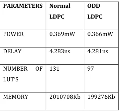
5.19. Comparison of Normal LDPC and ODD LDPC
Table 2. Comparison of Existing and proposed systems.
5.20. Comparison of Normal LDPC and FULL LDPC
Table 3. Comparison of Existing and Proposed Systems
5.21. Comparison of Normal LDPC and EVEN LDPC
Table 4. Comparison of Existing and Proposed Systems
PARAMETERS Normal LDPC EVEN LDPC
POWER 0.295mW 0.230Mw
DELAY 4.283ns 4.270ns
NUMBER OF LUT’S 97 97
MEMORY 212564Kb 212246Kb
When the comparison of both systems in this paper, so determined the above tables (5.19, 20 and 21). to reduce the power dissipation due to the 1 to sch-3 ( sch -scheme) and reaming parameters (LUTs, Slices) is also reduced to the data encoding techniques for low power VLSI system. The better results for LDPC Encoding Techniques comparison with the Data Encoding Techniques.
6.Conclusion and Future Work :
In this paper, a collection of latest data encoding schemes geared towards reducing the dynamic power dissipated by the links of a NoC. In Proposed system, Data programming techniques which are used in the place of encoders in LDPC that reduces the power utilization by eliminating the transitions as mentionedbefore. Hence analyzed the power consumption for these three data encoding schemes and scrutinized their power and area performances.
In the future, the implementation of Network on Chip (NOC) using different kinds of routers and link techniques are analyzed. Comparison on many Encoding techniques such as LDPC encoding techniques to be analyzed in which the area, delay, power and therefore the performance of the Network-On-Chips are investigated and use for high speed applications.
PARAMETERS Normal LDPC
ODD LDPC
POWER 0.369mW 0.366mW
DELAY 4.283ns 4.281ns
NUMBER OF LUT’S
131 97
MEMORY 2010708Kb 199276Kb
PARAMETERS Normal LDPC
FULL LDPC
POWER 0.328mW 0.318Mw
DELAY 4.276ns 4.274ns
NUMBER OF LUT’S
131 97
[image:10.595.287.513.162.324.2] [image:10.595.71.265.163.343.2]© 2017, IRJET | Impact Factor value: 5.181 | ISO 9001:2008 Certified Journal | Page 1459
7.References :
1) Nima Jafarzadeh, Maurizio Palesi, Ahmad Khademzadeh, Ali Afzali Kusha, “Data Encoding Techniques for Reducing Energy Consumption in Network On Chip” IEEE transactions on VLSI systems, Volume. 22, Issue .3, pp, 675-685, (2014).
2) International Technology Roadmap for
Semiconductors,(2011) [Online].Available:
http://www.itrs.net
3) Mr. S .R. Mullainath & Mr. S. Ramkumar, “Switching Reduction Through Data Encoding Techniques in NoC”, IEEE, Volume. 23, Issue.76, pp, 38-41 (2014).
4) S. Anusuyahdevi & Dr. S. Jayashri, “Performance Analysis of an Efficient Low Power NOC Router System Using Gray Encoding Techniques”,(ijircce), Volume. 2, Issue.12, pp, 7463-7470, (2014).
5) Wayne Wolf, Fellow, Ahmed Amine Jerraya & Grant Martin, “Multiprocessor System-on-Chip (MPSoC) Technology” IEEE, Volume. 27, Issue .10, pp, 1701-1713 (2008).
6) L. Benini & G. De MSicheli, “Networks on chips: A new SoC paradigm,” Computer, Volume. 35, issue.1, pp.70–78, (2002).
7) George vlantis, “Low Density Parity Check Code” doc: IEEE , pp.1-13 (2006).
8) Manjunatha P. N , T. S. Bharath Kumar & Dr . M. Z. Kurian “Architecture for Low Density Parity Check Encoder” (IJAIEM), Volume. 3, Issue 3, pp. 414-417 (2014).
9) M.Sakthivel, M. Karthick Raja, K.R. Ragupathy & K.Sathish Kumar, “Performance Comparison of EG - LDPC codeswith maximum likelihood Algorithm over non-binary LDPC codes” (IJCSITY) Volume.2, Issue.2, pp, 43-53 (2014).
10) Tuan Ta, University of Texas at Austin “A Tutorial on Low Density Parity Check Codes “ pp, 1-15, (2003).
11) Chetna N. Kharkar, M. M. Jadhav & A. M. Sapkal, “FPGA Implementation of linear LDPC encoder” Volume. 2, Issue. 11, (2013).