distribution in brushless permanent-magnet machines
.
White Rose Research Online URL for this paper:
http://eprints.whiterose.ac.uk/874/
Article:
Zhu, Z.Q., Howe, D. and Chan, C.C. (2002) Improved analytical model for predicting the
magnetic field distribution in brushless permanent-magnet machines. IEEE Transactions
on Magnetics, 38 (1 (Par). pp. 229-238. ISSN 0018-9464
https://doi.org/10.1109/20.990112
[email protected] https://eprints.whiterose.ac.uk/
Reuse
Unless indicated otherwise, fulltext items are protected by copyright with all rights reserved. The copyright exception in section 29 of the Copyright, Designs and Patents Act 1988 allows the making of a single copy solely for the purpose of non-commercial research or private study within the limits of fair dealing. The publisher or other rights-holder may allow further reproduction and re-use of this version - refer to the White Rose Research Online record for this item. Where records identify the publisher as the copyright holder, users can verify any specific terms of use on the publisher’s website.
Takedown
If you consider content in White Rose Research Online to be in breach of UK law, please notify us by
IEEE TRANSACTIONS ON MAGNETICS, VOL. 38, NO. 1, JANUARY 2002 229
Improved Analytical Model for Predicting
the Magnetic Field Distribution in Brushless
Permanent-Magnet Machines
Z. Q. Zhu, Senior Member, IEEE, David Howe, and C. C. Chan, Fellow, IEEE
Abstract—A general analytical technique predicts the magnetic
field distribution in brushless permanent magnet machines equipped with surface-mounted magnets. It accounts for the effects of both the magnets and the stator windings. The technique is based on two-dimensional models in polar coordinates and solves the governing Laplacian/quasi-Poissonian field equations in the airgap/magnet regions without any assumption regarding the relative recoil permeability of the magnets. The analysis works for both internal and external rotor motor topologies, and either radial or parallel magnetized magnets, as well as for overlapping and nonoverlapping stator windings. The paper validates results of the analytical models by finite-element analyses, for both slotless and slotted motors.
Index Terms—Electrical machines, magnetic field, permanent
magnet.
I. INTRODUCTION
A
N ACCURATE knowledge of the magnetic field dis-tribution is a prerequisite for predicting performance parameters, such as torque, back-emf, stator and rotor losses, demagnetization withstand, winding inductances, noise and vibration, etc., of brushless permanent magnet motors. Boules [1] formulated a two-dimensional (2-D) model in polar coor-dinates that utilized the concept of equivalent current-carrying coils to determine the airgap flux density distribution in a permanent magnet motor. The model could account for the effect of flux focusing in the magnets, as well as magnetization distribution, i.e., radial or parallel, on the flux per pole and the airgap flux density waveform. However, it only provided field solutions at the stator and rotor surfaces, which is usually insufficient for accurately predicting the performance of slot-less motor topologies. Laporte [2], using the same technique, subsequently derived the field solution in the airgap. However, both [1], [2] approximated the relative recoil permeability of the permanent magnets, i.e., , as unity, which causes an error in the calculation of the flux density [1]. Earlier, the authors developed an improved analytical technique for the calculation of the open-circuit field distribution [3], which was based on a 2-D polar coordinate model and catered for both internal and external rotor motor topologies. It involved the solution of the governing Laplacian/quasi-Poissonian fieldManuscript received June 8, 1999; revised October 11, 2001.
Z. Q. Zhu and D. Howe are with the Department of Electronic and Electrical Engineering, University of Sheffield, Sheffield S1 3JD, U.K.
C. C. Chan is with the Department of Electrical and Electronic Engineering, University of Hong Kong, Hong Kong.
Publisher Item Identifier S 0018-9464(02)00395-3.
equations in the airgap/magnet regions without any assumption regarding the relative recoil permeability of the magnets other than the fact that it is constant. However, the model presented in [3] was only applicable to machines equipped with radially magnetized magnets. Recently, Rasmussen [4] extended the model to account for the tangential magnetization component which exists in practice in a multipole impulse magnetized isotropic ring magnet. This paper extends the model further to cater for both radial and parallel magnetization, and also extends the analytical model [5] for predicting the magnetic field produced by the stator windings, to make it applicable to both overlapping and nonoverlapping winding configurations. Analytically calculated field distributions from both models are compared with finite element predictions for a slotless motor having both a radial and a parallel magnetized rotor, and for a slotted motor having a parallel magnetized rotor and both overlapping and nonoverlapping stator windings.
II. RADIAL ANDPARALLELMAGNETIZATION
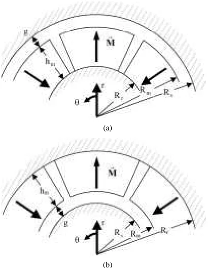
For the permanent magnet motors, Fig. 1, the field vectors and are coupled by
in the air spaces (1a)
in the permanent magnets (1b)
where is the residual magnetization vector, is the perme-ability of free space, and is the relative recoil permeability.
For the case of a multipole machine equipped with magnets having a linear second-quadrant demagnetization characteristic, the amplitude of the magnetization vector is
(2)
whilst the direction of is dependent on the imparted orienta-tion and magnetizaorienta-tion of the magnets. In polar coordinates, the magnetization is given by
(3)
Fig. 2 compares radial and parallel magnetization distributions, the components of which can be described, over one pole-pair, by
(4a)
(a)
[image:3.612.63.268.61.325.2](b)
Fig. 1. Motor topologies. (a) Internal rotor. (b) External rotor.
(a)
[image:3.612.339.518.63.415.2](b)
Fig. 2. Parallel and radial magnetization. (a) Radial magnetization. (b) Parallel magnetization.
(4b)
(4c)
(4d)
(4e)
for radial magnetization, and
(a)
(b)
Fig. 3. Waveforms of magnetization components M and M (a) Radial magnetization. (b) Parallel magnetization.
(5a)
(5b)
(5c)
(5d)
(5e)
[image:3.612.309.555.473.621.2]ZHU et al.: IMPROVED ANALYTICAL MODEL FOR PREDICTING MAGNETIC FIELD DISTRIBUTION 231
, for both radial and parallel magnetization. and can be expressed as Fourier series, i.e.,
(6a)
(6b)
where for radial magnetization
(7a)
(7b)
and for the parallel magnetization
(7c)
(7d)
where
for
for
III. FIELDPRODUCED BYMAGNETS
In order to obtain an analytical solution for the airgap field distribution produced by multipole magnets mounted on the sur-face of an iron-cored rotor, the following assumptions are made. 1) The permanent magnets have a linear demagnetization char-acteristic, and are fully magnetized in the direction of magne-tization. 2) End-effects are neglected. 3) The stator and rotor back-iron is infinitely permeable.
In terms of the scalar magnetic potential function
and (8)
Whilst the scalar magnetic potential distribution in the airgap is governed by Laplacian equation, in the permanent magnet regions it is governed by the quasi-Poissonian equation, i.e.,
in the airgap
(9a)
in the magnets
(9b)
and from (6)
(10a)
where
(10b)
The boundary conditions for internal [Fig. 1(a)] and external [Fig. 1(b)] rotor motors are defined by
(11a)
(11b)
(11c)
(11d)
where the dimensions , and are defined in Fig. 1. and for an internal rotor motor,
and and for an external rotor
motor, being the effective airgap length—which is the actual airgap length for a slotted motor and the sum of the airgap length and the radial thickness of the windings for a slotless motor, and is the radial thickness of the magnets.
General solutions to the governing (9) and (10a) are obtained as
(12)
in the airgap, and
(13)
for , and
(14)
for , in the magnets, where , , , , , are constants determined by applying continuity condi-tions (11).
Hence, the complete solution for the magnetic field compo-nents in the airspace/magnet regions can be deduced from the general solution of Laplacian/quasi-Poissonian equations and the specified boundary conditions.
In the airspace, they can be expressed as
(15a)
(15b)
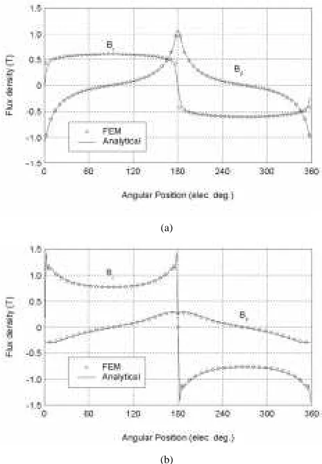
(a)
[image:5.612.51.282.59.391.2](b)
Fig. 4. Distribution of airgap field components in slotless motor with parallel magnetized magnets. (a) In airgap (r = 40:5 mm). (b) In magnets (r = 35:6 mm).
(16)
When , in order to ease numerical computation, it is convenient to write the solutions in different forms for the internal motor and the external motor.
Thus, for an internal rotor motor,
(a)
(b)
Fig. 5. Distribution of airgap field components in slotless motor with radial magnetized magnets. (a) In airgap (r = 40:5 mm). (b) In magnets (r = 35:6 mm).
(17)
Similarly, for an external rotor motor,
(18)
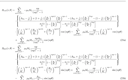
The field distribution in the magnets can also be deduced as seen in (19) at the bottom of the next page, when .
[image:5.612.312.544.62.396.2]ZHU et al.: IMPROVED ANALYTICAL MODEL FOR PREDICTING MAGNETIC FIELD DISTRIBUTION 233
For an external rotor motor, see (21) at the bottom of the next page, where for
for parallel magnetization
for radial magnetization
and for
for parallel magnetization for radial magnetization.
The developed models have been applied to a three-phase, slotless permanent magnet brushless motor with an internal rotor and either radial or parallel magnetized magnets. The relevant parameters of the motor are: ; mm;
mm; mm; , , .
Figs. 4 and 5 show excellent agreement between analytically and finite element predicted distributions of the radial and tangential field in the airgap and the magnets.
In the preceding analysis, the analysis of the magnetic field distribution due to the permanent magnets neglected the effect
(19a)
(19b)
(20a)
of stator slots, which both reduce the flux per pole and modify the field distribution [6], [7]. However, the effect of slotting can be accounted for by introducing a “2-D” relative perme-ance function, as described in [6]. By way of example, Fig. 6 compares analytically and finite element predicted distributions of the radial field component at a radius which corresponds to the surface of the magnets, the center of the magnets, and the surface of the rotor hub, respectively, for a slotted permanent magnet brushless motor, whose main parameters are given in Table I. It clearly indicates that the influence of stator slotting decays very quickly with distance from the stator bore.
IV. FIELDPRODUCED BYWINDINGS
An analytical expression for the field in the airgap/magnet region due to a three-phase overlapping winding in a slotted brushless motor has been derived by the authors [5]. It was also based on a 2-D polar coordinate model, in which the stator ampere-conductors were represented by an equivalent current sheet, distributed across the slot openings. This model has been further extended to cater for a nonoverlapping winding, Fig. 7. However, in order to avoid duplication, the analysis is not de-rived since it is essentially the same and the field produced by a three-phase overlapping or nonoverlapping stator winding can be generalized as
(22)
where is referenced to the axis of phase A, whose current is zero at , i.e., . In a brushless dc motor, the phase winding current waveform contains significant harmonics
, where is the order of the nontriplen harmonics, i.e., is the associated harmonic phase angle, and
and
for an overlapping winding (23a)
and
for a nonoverlapping winding (23b)
where , is the number of series turns per phase, is the slot-opening factor and is the winding factor, and being the winding distribution factor and winding pitch factor, respectively [5]. ) is a func-tion which accounts for the effect of curvature and is dependant on the radius and harmonic order, and is defined as
(24)
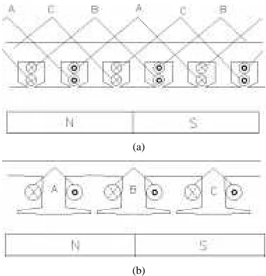
As can be seen from (23), the only difference which arises from the two different winding configurations is in the order of the field harmonics. For a nonoverlapping winding, the number
(21a)
ZHU et al.: IMPROVED ANALYTICAL MODEL FOR PREDICTING MAGNETIC FIELD DISTRIBUTION 235
(a) (b)
[image:8.612.63.531.60.421.2](c)
Fig. 6. Field distribution in rotor magnets of slotted motor. (a) Outer surface of magnets. (b) Center of magnets. (c) Inner surface of magnets (rotor hub).
TABLE I
MAIN PARAMETERS OF SLOTTED
BRUSHLESSMOTOR
of slots per pole per phase is , the winding comprising concentrated coils without end-winding overlapping and whose span equals one slot-pitch, which is less than the pole-pitch. Thus, the winding distribution factor is always equal to 1, whilst the winding pitch factor is always less than 1. In
(a)
(b)
Fig. 7. Stator winding configurations. (a) Overlapping. (b) Nonoverlapping.
contrast, for an overlapping winding both and are de-pendant on the number of slots per pole per phase, being 1 when the number of slots per pole per phase is 1 and being 1 when a full pitched winding is employed. Consequently, for a nonoverlapping winding, the space harmonic order
[image:8.612.331.522.454.652.2](a)
[image:9.612.65.531.61.432.2](b)
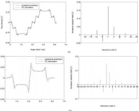
Fig. 8. Comparison of stator winding field distribution (att = 0) at surface of rotor magnets and associated harmonics. (a) Overlapping winding. (b) Nonoverlapping winding.
Fig. 9. Simulated phase current waveform of brushless motor at full load and rated speed.
an overlapping winding contains only odd harmonics, as can clearly be seen in the harmonic spectra of Fig. 8, which com-pares the analytically predicted field distribution at the surface of the magnets, i.e., due to equivalent overlapping and
[image:9.612.46.286.484.661.2]ZHU et al.: IMPROVED ANALYTICAL MODEL FOR PREDICTING MAGNETIC FIELD DISTRIBUTION 237
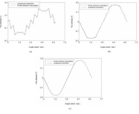
(a) (b)
[image:10.612.62.533.59.447.2](c)
Fig. 10. Field distributions in rotor magnets due to stator mmf (t = 0). (a) Outer surface of magnets. (b) Center of magnets. (c) Inner surface of magnets (rotor hub).
V. CONCLUSION
An analytical technique which was developed by the authors for predicting the field distributions produced by the mag-nets and the stator winding of permanent magnet machines equipped with surface-mounted magnets has been extended. It is still based on polar coordinate 2-D models, and involves the solution of the Laplacian/quasi-Poissonian field equations in the airgap/magnet regions, and makes no simplifying assumption regarding the relative recoil permeability of the magnets. However, it now caters for 1) internal and external rotor motor topologies; 2) radial and parallel magnetization; 3) overlapping and nonoverlapping stator winding configurations; and 4) slotted and slotless stators. The developed analysis has been validated by finite element analyses on both slotless and slotted motors. It is generally applicable to surface-mounted permanent magnet machines.
ACKNOWLEDGMENT
The authors acknowledge the contributions of former col-leagues, Dr. Ng K. and Dr. Chen Y.S., for providing the finite element results.
REFERENCES
[1] N. Boules, “Prediction of no-load flux density distribution in permanent magnet machines,” IEEE Trans. Ind. Applicat., vol. IA-21, pp. 633–643, July-Aug. 1985.
[2] B. Laporte and C. Berenger, “Permanent magnet synchronous machines owning windings in the airgap,” in Proc. Int. Conf. Electrical Machines, 1988, pp. 29–34.
[3] Z. Q. Zhu, D. Howe, E. Bolte, and B. Ackermann, “Instantaneous mag-netic field distribution in brushless permanent magnet dc motors, Parts I: open-circuit Field,” IEEE Trans. Magn., vol. 29, pp. 124–135, Jan. 1993.
[4] K. F. Rasmussen, “Analytical prediction of magnetic field from surface mounted permanent magnet motor,” in Proc. Int. Electrical Machines and Drives Conf.. Seattle, WA, 1999, pp. 34–36.
[5] Z. Q. Zhu and D. Howe, “Instantaneous magnetic field distribution in brushless permanent magnet dc motors, Parts II: armature-reaction Field,” IEEE Trans. Magn., vol. 29, pp. 136–142, Jan. 1993.
[6] , “Instantaneous magnetic field distribution in brushless permanent magnet dc motors, Part III: Effect of stator slotting,” IEEE Trans. Magn., vol. 29, pp. 152–151, Jan. 1993.
[7] U. Kim and D. K. Lieu, “Magnetic field calculation in permanent magnet motors with rotor eccentricity: with slotting effect considered,” IEEE Trans. Magn., vol. 34, pp. 2253–2266, July 1998.
Z. Q. Zhu (M’90, SM’00) received the B.Eng. and M.Sc. degrees from
Zhe-jiang University, China, in 1982 and 1984, respectively, and the Ph.D. degree from the University of Sheffield, U.K., in 1991, all in electrical and electronic engineering.
From 1984 to 1988, he lectured in the Department of Electrical Engineering at Zhejiang University. Since 1988, he has been with the University of Sheffield, where he is currently Professor of Electronic and Electrical Engineering. His current major research interests include applications, control, and design of per-manent magnet machines and drives.
Prof. Zhu is a Chartered Engineer and a Member of IEE, U.K.
David Howe received the B.Tech and M.Sc. degrees from the University of
Bradford, U.K., in 1966 and 1967, respectively, and a Ph.D. from the University of Southampton, U.K., in 1974, all in electrical power engineering.
He has held academic posts at Brunel and Southampton Universities, and spent a period in industry with NEI Parsons Ltd working on electromagnetic problems related to turbo-generators. He is currently Professor of Electrical En-gineering at the University of Sheffield, U.K., where he heads the Electrical Machines and Drives Research Group. His research activities span all facets of controlled electrical drive systems, with particular emphasis on permanent magnet excited machines.
Prof. Howe is a Chartered Engineer and a Fellow of the IEE, U.K.
C. C. Chan (F’92) received the B.Sc., M.Sc., and Ph.D. degrees in 1957, 1959
and 1981 from China University of Mining and Technology, Tsinghua Univer-sity and UniverUniver-sity of Hong Kong, respectively, all in electrical engineering. In 1992, he was awarded the Honorary D.Sc. degree from the Odessa Polytechnic University, Ukraine.
He has been working for 11 years in industry and 31 years in academic in-stitutions. He is currently Professor in the Department of Electrical and Elec-tronic Engineering at the University of Hong Kong. His research activities in-volve electric vehicles, electrical machines and control.