SMART DETECTOR DATABASE USING RFID
SHAHIRAH BINTI MD EMRAN
This Report Is Submitted In Partial Fulfilment of Requirements fort he Bachelor of Electronics Engineering (Telecommunication Electronics) With Honours
Faculty of Electronics and Computer Engineering UniversitiT eknikal Malaysia Melaka
UNIVERSTI TEKNIKAL MALAYSIA MELAKA FAKULTI KEJURUTERAAN ELEKTRONIK DAN KEJURUTERAAN
KOMPUTER
BORANG PENGESAHAN STATUS LAPORAN PROJEK SARJANA MUDA II
Tajuk Projek Sesi
Pengajian
SMART DETECTOR DAT ABASE USING RFID
1 2 I 1 3
Saya SHAHIRAH BINTI MD EMRAN
(HURUF BESAR)
mengaku membenarkan Laporan Projek Sarjana Muda ini disimpan di Perpustakaan dengan sy arat-syarat kegunaan seperti berikut:
I. Laporan adalah hakmilik Universiti Teknikal Malaysia Melaka.
2. Perpustakaan dibenarkan membuat salinan untuk tujuan pengajian sahaja.
3. Perpustakaan dibenarkan membuat salinan laporan ini sebagai bahan pertukaran antara institusi pengajian tinggi.
4. Sila tandakan (
.J)
:
D
SULIT*D
TERHAD**0
TIDAK TERHAD*(Mengandungi maklumat yang berdarjah keselamatan atau kepentingan Malaysia sepeni yang termaktub di dalam AKT A RAH SIA RASMI I 972)
**(Mengandungi maklumat terhad yang telah ditentukan oleh organisasilbadan di mana penyelidikan dijalankan)
(TAND~AN
PENULIS) (COP DAN TANDA TA NGAN PE NYE LIA) Mohamad Harris Bin MisranPensyarah
Tarikh: ---'~o ~JU~N~20~1~3 _ _
~akulti. Ke1ur.uteraan ~lektronik Dan Kejuruteraan Komputer
IJn1vers1ti Teknikal Malaysia Melaka (UTeM) Hang Tu11h Jaya
76100 Durian Tunggal, Melaka
111
"I recognize this report is the result of my own work except for a summary and quote
of each of them I have mentioned the source"
Signature : ...
~
... .Author Name : SHAHIRAH BINTI MD EMRAN
"I I we declare that I have read this on my mind I we are of sufficient scope and
quality of the award of Bachelor of Electronics Engineering (Telecommunication
Electronics) With Honours"
Signature
Supervisor Name
Date
i
: MOHAMAD HARRIS BIN MISRAN
: I 0 June 2013
v
This project is lovingly dedicated to my beloved parents who have been my constant
source of inspiration. They have given me the drive and discipline to tackle any task
with enthusiasm and determination. Without their love and support this report would
VI
ACKNOWLEDGEMENT
In the name of Allah S.W.T, the Most Gracious, the Ever Merciful. Praise is to Allah, Lord of the Universe and Peace and Prayers be upon His final Prophet and Messenger Muhammad S.A.W.
I wish to thank various people for their contribution to this project;
Mr.MohamadRiza bin Hadrun, Head of Division ofSenstechSdn. Bhd., for their valuable technical support on this project; Mdm. NurHidayahbintiMohamadYatim,
for their help in collecting the plant data and to Miss EryanaEiydaBintiHussin,
master student in UTeM who helped me in handling the instruments.
Special thanks should be given to Mr.Mohamad Harris bin Misran, my research project supervisor for her professional guidance and valuable support and
for his useful and constructive recommendations on this project.Without this continued support and interest, this project would not have been the same as presented here.
My sincere appreciation also extends to my father, mother and my family and not forgetter to all my colleagues and others who have provided assistance at various
occasions. Their views and tips are useful indeed. Unfortunately, it is not possible to list all of them in this limited space. Finally, special thanks extended to my beloved family who had given me moral support and prayed for my success.
Vil
ABSTRACT
A Smart Detector Database using Radio Frequency Identification (SDDR) is
a cyclist tracking device. This device can be applied in the biggest race competition,
such as in the Le Tour De Langkawi (LTDL). Todays, the monitoring system used unable to trace not arrive cyclist. As a solution, SDDR will detect cyclist that through
the checkpoints and the profile about that cyclist would be displayed at the
organizers PC monitor at the last point. The profile of each cyclist can be identified
by using the information from database. The information from the Radio Frequency
Identification (RFID) Database Handling System will be used by the organizer such
as name, address, date and time of arriving at the each checkpoint. The main purpose
of this device is to reduce the use of manpower atthe each checkpoint.The aim of this
project is to implement the RFID tags and readers as a detector. This project will use
the Ultra High Frequency (UHF) RFID Reader that will be directly connected to the
PC organizer without using the interface circuit. This system has been developed by
using Microsoft Visual Basic (VB) that offered graphical user interface (GUI) for
display the result. The database as well support for this system is Microsoft Access
(MA). The purpose of database is to be reference for any related stored data and
information. Implementation of this smart detector involves low cost, long read range
and high read rate. The successfully implementation for this project will save time,
VIII
ABSTRAK
Smart Detector Database using Radio Frequency Identification ataupun
boleh dikenali sebagai SDDR adalah sebuah alat pengesan pelumba berbasikal. Alat
ini boleh diaplikasikan semasa pertandingan atau perlumbaan basikal yang besar
berlangsung seperti Le Tour De Langkawi (LTDL). Hari ini, sistem pemantauan yang
digunakan tidak dapat mengesan pelumba yang tidak sampai ke garisan penamat.
Sebagai penyelesaian, SDDR digunakan untuk mengesan pelumba yang melalui pos
pemeriksaan ataupun tempat pemeriksaan dan maklumat diri pelumba akan
dipaparkan di skrin komputer pihak penganjur yang terletak di garisan penamat.
Butiran terperinci mengenai setiap pelumba boleh dikenal pasti dengan
menggunakan maklumat daripada pangkalan data. Maklumat daripada Pangkalan
Data Pengendalian Sistem Identifikasi Frekuensi Radio (RFID) akan digunakan oleh
pihak penganjur seperti nama, alamat, tarikh dan waktu ketibaan pelumba di setiap
tempat pemeriksaan. Tujuan utama alat ini adalah untuk mengurangkan penggunaan
tenaga kerja di setiap tempat pemeriksaan. Matlamat projek ini adalah untuk
melaksanakan penggunaan tag dan pembaca bagi RFID dalam bidang pengesanan.
Projek ini akan menggunakan Pembaca UHF yang akan dihubungkan terns kepada
komputer penganjur tanpa menggunakan sebarang litar antaramuka. Sistem ini akan
dibangunkan dengan menggunakan Microsoft Visual Basic (VB) yang menawarkan
Antaramuka Pengguna Grafik atau Graphical User Interface (GUI) untuk
memaparkan keputusan. Pengkalan data sebagai sokongan untuk sistem ini
menggunakan Microsoft Access (MA). Tujuan pangkalan data adalah untuk menjadi
rujukan bagi mana-mana data yang disimpan dan maklumat yang berkaitan.
Pelaksanaan pengesan pin tar ini melibatkan kos yang rendah, jarak bacaan yang jauh
and kadar bacaan yang tinggi. Jika projek ini berjaya dilaksanakan, ia pasti akan
IX
TABLE OF CONTENTS
CHAPTER TITLE PAGES
PROJECT TITLE
REPORT VERIFICATION II
DECLARATION Ill
DEDICATION v
ACKNOWLEDGEMENT VI
ABSTRACT vii
ABSTRAK VIII
TABLE OF CONTENTS IX
LIST OFT ABLES XII
LIST OF FIGURES xiii
LIST OF ABBREVIATIONS xv
LIST OF APPENDIXES XVII
I INTRODUCTION
1.1 Project Background
l.2 Objective of Project 3
l.3 Problem Statement 4
1.4 Scope of Project 4
II LITERATURE REVIEW
2.1 History of RFlD 2.2 RFlD System 2.3 Frequency 2.4 RFlD Tag
2.4.1 Operation of Multiple Tags 2.4.2 Advantages and disadvantages
RFlD tags
2.5 RFlD Reader and Antenna
2.5.1 XR400 UHF RFID Reader 2.5.2 UHF RFlD Antenna 2.6 Database Technology
2.7 Graphical User Interface (GUI)
III PROJECT OF METHODOLOGY
3.1 Block Diagram
3.2 Project of Methodology 3.3 Block Diagram of Project 3.4 Hardware Development
3.4.1 RFlD Connections 3.5 Software Development
3.5.1 Database Handling Design 3.5.2 GUI Design
IV RESULT AND DISCUSSION
V CONCLUSION AND RECOMMENDATION
5.1
5.2
Conclusion
Recommendation
REFERENCES
APPENDIXES
57
58
60
NO 2.1 2.2 2.3 2.4 2.5 2.6 2.7
4.1
4.2
4.3
4.4
LIST OF TABLES
TITLE
Historical timetable of technologies and efforts related to
RFID development
Comparison between RFID and Barcode
Differences between Active RFID and Passive RFID tags
Advantages and disadvantages of RFID tags
XR Series RFID Reader, Read/Write settings
XR400 UHF RFID reader specification
UHF RFID antenna specification
Test of range detection without obstacle
Average of minimum and maximum height without
obstacle
Test of range detection with obstacle
Average of minimum and maximum height with obstacle
XIII
LIST OF FIGURES
NO TITLE PAGES
l.l The connection of RFID system 2
2.1 RFID system element 9
2.2 RFID tags operating 11
2.3 Example of passive RFID tags with adhesive 13
2.4 Master-slave architecture of the RFID system 14
2.5 RFID Tag Component 15
2.6 Passive RFID tags for l 25kHz 15
2.7 Active RFID tags for 433MHz 16
2.8 Inductive coupling 17
2.9 Reading moving tags 18
2.10 Multiple tag operation 19
2.11 Active RFID reader for 433MHz 22
2.12 Passive RFID reader for l 25kHz 22
2.13 XR400 UHF RFID reader 24
2.14 UHF Motorola (Symbol) Antenna 25
2.15 Official logo of Microsoft Access 2010 28
2.16 Microsoft Access 2010 filling table 28
2.17 Official logo of Microsoft Visual Basic Professional 29
Edition
2.18 Starting page for VB 9.0 30
XIV
RFID
3.3 Block diagram of project for Smart Detector Database 34
using RFID
3.4 XR Series RFID Reader physical connections 35
3.5 The antenna cable 36
3.6 Tx and Rx connection of antenna port 36
3.7 N connector 37
3.8 TNC connector 37
3.9 UHF RFID Reader and power adapter 38
3.10 RJ45 Ethernet cable 38
3 .11 Light indicator of the reader 39
3.12 Console Login 39
3.13 Main page of the reader administration console 40
3.14 Flow chart of database handling design 41
3.15 Microsoft Access 2007 database 42
3.16 Information stored in database 42
3.17 GUI Development 43
3.18 Microsoft Visual Basic 2008 Professional Edition start 44
page
3.19 VB display for create new form 45
3.20 Main page of SDDR by using VB display 45
4.1 Information stored in database 47
4.2 Design of programming in Visual Basic system 47
4.3 Login page 48
4.4 Main page of the smart detector software system 48
4.5 Cyclist profile page 49
'
4.6 Page of tags detection for smart detector database system 49
4.7 Graph distance versus height without obstacle 52
4.8 Graph distance versus angle without obstacle 52
4.9 Graph distance versus height with obstacle 55
xv
LIST OF ABBREVIATIONS
SDDR Smart Detector Database using RFID RFID Radio Frequency Identification
ID Identification
UHF Ultra-high frequency VB Visual Basic
MA Microsoft Access GUI Graphical User Interface LTDL Le Tour De Langkawi
PC Personal Computer
TNC Threaded Neill-Concelman connector N Neill connector
LAN Local Area Network UWB Ultra-wideband
IFF Identification, friend or foe WWII World War II
FCC Federal Communications Commission EPC Electronic Product Code
DoD U. S Department of Defence MSSI Multispectral Solutions Inc.
RF Radio Frequency LF Low Frequency HF High Frequency
RAD Tx
Rx
XML
Rapid Application Development Transmitter
Receiver
Extensible Markup Language
NO
A
B
c
D
E
LIST OF APPENDIXES
TITLE
Visual Basic Coding of Smart Detector Database System for Login Page
Visual Basic Coding of Smart Detector Database System for Main Page
Gantt Chart
XR Series RFID Readers Manual: Getting Started
XR Series RFID Readers Manual: Installation and Communication
XVII
PAGES
63
64
65
CHAPTER I
INTRODUCTION
1.1 Project Background
Nowadays, to make the biggest race competition such as Le Tour De
Cyclist through the
checkpoint
RJ45 Ethernet cable
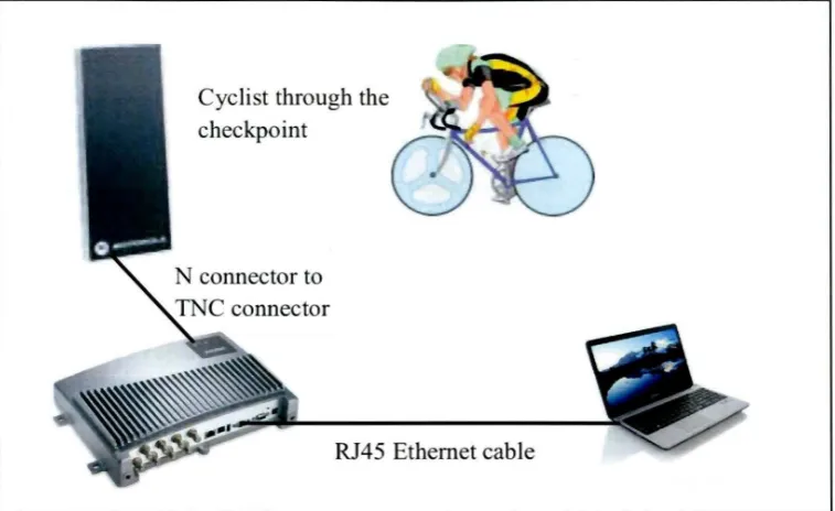
Figure I. I: The connection of RFID system
2
Figure l. I shows the RFID system connection between the transponder and the reader in this project. When the cyclist passed the antenna that installed at the
each checkpoint, the antenna will capture the data that carried in the tags and send to
the RFID reader through the antenna cable. The data will transferred to the PC monitor from the RFID reader through the RJ45 Ethernet cable. Lastly, the information of cyclist will displayed at the organizer PC monitor.
This project can be used to manage the systems that detect the cyclist arrived
at the checkpoint. Furthermore, this system also helps the organizer to knows where
the last checkpoint of cyclist pass through and which the checkpoint they do not
through it. By the means of that, organizer could track who is missing during the
events. If they need an assist, the rescuing team will send to find them faster.
There are three parts in the RFID system. The first part is a scanning antenna
which is RFID reader, the second part is a transceiver with a decoder to interpret data
[image:19.516.103.482.80.312.2]3
the result. The supported database in this system is used Microsoft Access (MA).The
purpose of this database is to be reference of any related stored data and information.
The improvements of this system can be used to overcome the limitation of
manpower to guide an each checkpoint. On the other hands, this project can monitor
for each cyclist that through the reader.
1.2 Objective of Project
This project has three main objectives that related to the software and the
hardware system. These objectives will be the reference during the development of
the project. The successfulness of this project are depending on the achieving these
objectives. The objectives listed are:
l. To implement the RFID tags and readers uses as a detector.
The first objective is to design the Smart Detector Database using RFID by
implement the RFID tags and readers. It will uses as a detector in this project. The
development of this project can overcome the limitation of the detection security in
monitoring system.
2. To learn the VB language that use for GUI system to display at the PC
monitor.
The second objective of this project is to learn the VB language. This
'
language can be used as interfaces by using the GUI system and will display it at the
PC monitor. The software part will covers all the important data about the cyclist
such as their profile and the time arriving at the checkpoint. The software that used in
this project are Microsoft Visual Basic 2008 Professional Edition and the database
used Microsoft Access 2007.
4
Lastly, the third objective for this project is to reduce the use of manpower at
the each checkpoint during the games. By implement this project in the big race
competition, manpower used during the games can be reduced.
1.3 Problem Statement
Todays, in Malaysia a lot of manpower is used to makes the big events
competition games likes L TDL games smoothly. This will involve high cost for each
event every year. This smart detector device is new ways to solve this problem by
develop the database using RFID. The challenge of this project is how far the data
will transfer using RFID when the tags placed at the bicycle passing the reader at the
checkpoint. It is because RFID is a radio frequency protocol device and has limited
range. When has any interruption while transmitting the data from the tag to the
reader such as blockage or overlap, the data might be loss and the reader cannot
receive the data as usual.
1.4 Scope of Project
A Smart Detector Database using Rf ID is a device that tracked the cyclist
that passes on the checkpoint during the game. The RFID tags which carrying the
data will place on the bicycle and can be read by the RFID reader. The data will be
transmitting to the RFID antenna by radio frequency signal the read point is the RF
range of an antenna. The reader will communicate with the tags and transfer the data
to a host computer by using the LAN cable. At the PC monitor, the coding is written
using the Microsoft Visual Basic programming. The data that store in the tag was
saved in the database using Microsoft Access.
In order to monitor the cyclist during the games with using less manpower,
this project has been fonned and design. This project are consist three parts which
5
When, the transponder is activated, the tag transmits the data back to the
antenna. For each RFID tags are consisting of unique ID that is means the RFID
antenna can receive the information from a certain distance. The RFID system will
integrate with the RFID Database Handling system and display the result that had
been received from the external database handler.
1.5 Thesis Outline
This report is a document that delivers the ideas generated and the concepts
are applied in this project. Chapter one contains the introduction of SDDR system.
The introduction consists of project background, objectives, problems statement,
scope and thesis outline.
While, in the chapter two is describe about the project literature review. In
order to execute this project, literature review must be done to comprehend the whole
system and to decide the best inputs, outputs and used devices. Data obtained from
the journals, books and internet.
In the chapter three explain the methodology of the project flow and its
functional block diagram. It also discusses the method used for the project, such as
the system operation, hardware and software applied.
Chapter four consist of actual result and analysis of thjs project. It included
all the main components together with the functionality and description applied in
this project. After that, the discussion about the project was written in this chapter.
Lastly, chapter five is the project conclusion and recommendation. This
chapter describe about the achievement for the whole project and gave the
CHAPTER II
LITERATURE REVIEW
In order to implement this project, the literature review must be done to
understand the whole system and to decide what the best input, output and the
devices that will be used. Literature review will help to gain more information about
the RFID technology, also for hardware and software development.
1.6 History of RFID
The Radio Frequency Identification (RFID) is an auto identification
technology that was developed in the 1940's [1]. RFID technology was a first
developed in order to differentiate between a friends and foes aircraft during the
Second World War. In the several years, RFID has come of age by the technology
advances in microelectronics, wireless communications and also computer networks
[2]. Todays, RFID become as one of the most rapidly growing segments of automatic identification data collection industry [3].
The other identification systems includes the barcode systems, optical character recognition system, smart cards and biometrics (including voice, fingerprinting and also retina scanning) is overcomes challenges for RFID system.
This is because it does not require the line-of-sight communication, sustains harsh
7
The First RFID Patents goes to Mario W. Cardullo was claims to have
received the first U.S. patent for an active RFID tag with rewritable memory on
January 23, 1973. That same year, the California entrepreneur, Charles Walton,
received a patent for a passive transponder used to unlock a door without a key. A
card with an embedded transponder communicated a signal to a reader near the door.
When the reader detected a valid identity number stored within the RFID tag, the
reader will unlocked the door. Walton licensed the technology to Schlage Lock of
San Francisco, the lock maker and other companies.
Later, companies developed a low-frequency ( 125 kHz) system, featuring
smaller transponders. A transponder encapsulated in glass could be injected under
the cows" skin. This system is still used in cows around the world today. Low
frequency transponders were also put in cards and used to control the access to
buildings [5].
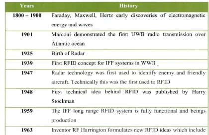
Table 2.1: Historical timetable of technologies and efforts related to RFID
development
Years History
1800 - 1900 Faraday, Maxwell, Hertz early discoveries of electromagnetic
energy and waves
1901 Marconi demonstrated the first UWB radio transmission over
Atlantic ocean
1925 Birth of Radar
1939 First RFID concept for IFF systems in WWII ,
1947 Radar technology was first used to identify enemy and friendly
aircraft. Technically this was the first used to RFID
1948 First technical idea behind RFID was published by Harry
Stockman
1959 The IFF long range RFID system is fully functional and beings
production
[image:24.516.51.471.442.714.2]