construction). The tradeoff coefficientsαandβare used based on the importance of the two objectives. Here, we adjust the coefficients so that these two terms are approximately of equal weights. In fact, these two terms are tradeoff terms and are different in different test cases. In order not to bias one side, we choose a pair ofαandβto balance the effects. Although we have observed a slight increase in I/O wirelength for “industry3” case containing many I/O-involved nets, we have ob-tained a better I/O timing performance by an averagely smaller I/O wirelength.
V. CONCLUSION
In this paper, we have presented an I/O clustering step, considering DC and performance optimization for high-end flip-chip design. We formulate the problem as a min-cost maximum flow problem, and the experimental results are encouraging. With a slight increase in the percentage of VDTV, we can automate the I/O buffer block generation, which, in turn, will yield an averagely better timing performance and a much less DC.
ACKNOWLEDGMENT
The authors would like to thank the anonymous reviewers for providing precious suggestions to greatly improve this paper.
REFERENCES
[1] Design of High-Performance Microprocessor Circuits, A. Chandrakasan, W. Bowhill, and F. Fox, Eds. Piscataway, NJ: IEEE Press, 2001. [2] L. Cao and J. Krusius, “A new power distribution strategy for area array
bonded ICS and packages of future deep sub-micron ULSI,” inProc. IEEE Electron. Compon. Technol. Conf., 1997, pp. 1138–1145. [3] P. Sandborn, M. Abadir, and C. Murphy, “The tradeoff between
periph-eral and area array bonding of components in multichip modules,”IEEE Trans. Compon., Packag., Manuf. Technol. A, vol. 17, no. 2, pp. 249–256, Jun. 1994.
[4] V. Maheshwari, J. Darnauer, J. Ramirez, and W.-M. Dai, “Design of FPGAS with area I/O for field programmable MCM,” inProc. ACM Symp. FieldProgramm. Gate Arrays, 1995, pp. 17–23.
[5] P. Buffet, J. Natonio, R. Proctor, Y. Sun, and G. Yasar, “Methodology for I/O cell placement and checking in ASIC designs using area-array power grid,” inProc. IEEE Custom Integr. Circuits Conf., 2000, pp. 125–128. [6] G. Yasar, C. Chiu, R. Proctor, and J. Libous, “I/O cell placement and
electrical checking methodology for ASICs with peripheral I/Os,” inProc. IEEE Int. Symp. Quality Electron. Des., 2001, pp. 71–75.
[7] R. Farbarik, X. Liu, M. Rossman, P. Parakh, T. Basso, and R. Brown, “CAD tools for area-distributed I/O pad packaging,” inProc. IEEE Multi-Chip Module Conf., 1997, pp. 125–129.
[8] P. Zuchowski, J. Panner, D. Stout, J. Adams, F. Chan, P. Dunn, A. Huber, and J. Oler, “I/O impedance matching algorithm for high-performance ASICs,” inProc. IEEE Int. ASIC Conf. Exhib., 1997, pp. 270–273. [9] J. Kozhaya, S. Nassif, and F. Najm, “I/O buffer placement
methodol-ogy for ASICs,” inProc. IEEE Int. Conf. Electron. Circuits Syst., 2001, pp. 245–248.
[10] R. Lomax, R. Brown, M. Nanua, and T. Strong, “Area I/O flip-chip packaging to minimize interconnect length,” inProc. IEEE Multi-Chip Module Conf., 1997, pp. 2–7.
[11] C. Tan, D. Bouldin, and P. Dehkordi, “Design implementation of intrinsic area array ICS,” inProc. 17th Conf. Adv. Res. VLSI, 1997, pp. 82–93. [12] J. McGrath, “Chip/package co-design: The bridge between chips and
systems,” inAdvanced Packaging Mag., Jun. 2001.
[13] J. Parker, R. Sergi, D. Hawk, and M. Diberardino, (2003, Nov.). “IC-package co-design supports flip-chips,” EE Times. [Online]. Available: http://www.eedesign.com/story/OEG20031113S0055 [14] K.-Y. Chao and D. Wong, “Signal integrity optimization on the pad
as-signment for high-speed VLSI design,” inProc. IEEE Int. Conf. Comput.-Aided Des., 1995, pp. 720–725.
[15] S. Nassif and J. Kozhaya, “Fast power grid simulation,” in Proc. ACM/IEEE Des. Autom. Conf., 2000, pp. 156–161.
[16] L. Pillage, R. Rohrer, and C. Visweswariah,Electronic andSystem Simu-lation Methods. New York: McGraw-Hill, 1995.
[17] A. Berman and R. Plemmons,Nonnegative Matrices in the Mathematical Sciences. Philadelphia, PA: SIAM, 1994.
[18] I.-M. Liu, H.-M. Chen, T.-L. Chou, A. Aziz, and D. Wong, “Integrated power supply planning and floorplanning,” in Proc. IEEE Asia South Pacific Des. Autom. Conf., 2001, pp. 589–594.
[19] R. Ahuja, T. Magnanti, and J. Orlin,Network Flows—Theory, Algorithms, andApplications. Englewood Cliffs, NJ: Prentice-Hall, 1993. [20] T. Cormen, C. Leiserson, and R. Rivest, Introduction to Algorithms.
Cambridge, MA: MIT Press, 1990.
[21] W. Choi and K. Bazargan, “Incremental placement for timing optimiza-tion,” inProc. IEEE Int. Conf. Comput.-Aided Des., 2003, pp. 463–466. [22] H. Yu, X. Hong, and Y. Cai, “MMP: A novel placement algorithm for
combined macro block and standard cell layout design,” inProc. IEEE Asia South Pacific Des. Automation Conf., 2000, pp. 271–276.
[23] P. Madden, “Reporting of standard cell placement results,”IEEE Trans. Comput.-Aided Des. Integr. Circuits Syst., vol. 21, no. 2, pp. 240–247, Feb. 2002.
[24] A. Caldwell, A. Kahng, S. Mantik, and I. Markov, “Implications of area-array I/O for row-based placement methodology,” inProc. IEEE Symp. IC/Package Des. Integr., 1998, pp. 93–98.
Efficient Static Compaction Techniques for Sequential Circuits Based on Reverse-Order Restoration
and Test Relaxation
Aiman H. El-Maleh, S. Saqib Khursheed, and Sadiq M. Sait
Abstract—The authors present efficient reverse-order-restoration (ROR)-based static test compaction techniques for synchronous sequential circuits. Unlike previous ROR techniques that rely on vector-by-vector fault-simulation-based restoration of test subsequences, the authors’ technique restores test sequences based on efficient test relaxation. The restored test subsequence can be either concatenated to the compacted test sequence, as in previous approaches, or merged with it. Furthermore, it allows the removal of redundant vectors from the restored subsequences using a state traversal technique and incorporates schemes for increasing the fault coverage of restored test subsequences to achieve an overall higher level of compaction. In addition, test relaxation is used to take ROR out of saturation. Experimental results demonstrate the effectiveness of the proposed techniques.
Index Terms—Fault coverage, linear reverse-order restoration (LROR), state traversal (ST), static compaction, test relaxation.
I. INTRODUCTION
The complexity of sequential automatic test pattern recognition (ATPG) is significantly higher than combinational ATPG [1]. For this reason, to maximize fault coverage, sequential ATPG uses heuristics that could result in large test sequences. For example, when genetic algorithms are employed, a high fault coverage is achieved, but at the expense of long test sequences [2].
The length of a test set for testing system-on-chip (SoC) crucially affects the test application time (TAT) and memory requirements of the tester. Therefore, test compaction focuses on reducing the length of a test set while maintaining its fault coverage. Test compaction
Manuscript received March 1, 2005; revised July 5, 2005 and September 22, 2005. This work was supported by King Fahd University of Petroleum and Minerals under Project FT 2004/07. This paper was recommended by Associate Editor S. M. Reddy.
The authors are with the Department of Computer Engineering, King Fahd University of Petroleum and Minerals, Dhahran 31261, Saudi Arabia (e-mail: [email protected]; [email protected]; [email protected]. edu.sa).
Digital Object Identifier 10.1109/TCAD.2006.873895
algorithms can be classified into two main classes, namely: 1) dynamic compaction and 2) static compaction. Dynamic compaction algorithms incorporate heuristics aimed at producing shorter test length into the test generation process; whereas, static compaction algorithms are applied as a postprocessing step to the test generation process. Static compaction is known to be more efficient for sequential circuits than dynamic compaction.
Static compaction algorithms for sequential circuits are useful for both scan and nonscan sequential circuits. Scan circuits benefit from these algorithms in two ways: 1) To reduce the number of scan operations that require a large number of clock cycles, sequences of primary inputs can be applied between scan operations. Static compaction can be effective in reducing the length of such primary input sequences [3]. 2) Recently, an approach called “transparent” scan was proposed, which considers a scan circuit as a sequential circuit with extra inputs and outputs corresponding to scan-chain inputs, scan-select input, and the scan-chain outputs [4]. Under this approach, static compaction algorithms for nonscan sequential circuits can be applied directly for scan circuits, without altering the algorithm.
Several well-known static compaction techniques are proposed in the literature. Pomeranz and Reddy proposed vector omission [5], which removes a test vector from the test set if it does not reduce the fault coverage. Hsiaoet al.[6] explored another aspect of vector omission in which test vectors that take the test set to the same state (cycles) without contributing to fault detection are removed. The idea is extended in [7] using relaxed state assignments, and a higher level of compaction is achieved by locating bigger cycles in the test set.
The results of vector omission showed that the majority of test vectors can be removed from the test set, which suggested that it would be more appropriate to find test vectors that are needed for maintaining the fault coverage rather than those that can be removed. This observation led to the concept of vector restoration [8].
Test vector restoration [8] removes all the test vectors and restores them one by one considering the target fault(s) in decreasing order of detection time. Test vectors are added to the compacted test set until the target fault is detected. The compacted test set is then fault simulated, and all the faults that are detected are dropped. This process continues until all the faults (detected earlier by the original test set) are detected. Restoration also produces a covering effect, as hard-to-detect faults that are detected toward the end have higher chances of detecting easy-to-detect faults that are detected by initial test vectors thrown randomly by ATPG. The restoration algorithm places test vectors in the original order of their appearance.
Many algorithms are developed on top of vector restoration. Linear reverse order restoration (LROR) was proposed by Guoet al.to speed up the vector restoration process [9]. The algorithm selects some faults, in decreasing order of detection time, restores test vectors using fault simulation, and places the restored test vectors toward the end of the compacted test sequence. Thus, only newly restored test vectors are fault simulated rather than the entire test set as in original vector restoration.
Another heuristic based on restoration is the single fault restoration (SIFAR), proposed by Lin et al. [10]. It targets a single fault in decreasing order of detection time and restores test vectors until the fault is detected. It uses parallel pattern simulation to speed up the restoration process, achieving better compaction results in lesser time than LROR [9].
Guoet al.improved LROR [11], [12] by making the following mod-ifications to their previous proposal [9]. During test vector restoration, if the algorithm comes across a time frame with undetected faults, then these faults are added to the target fault list and restoration continues. Results obtained by this modified method were comparable to SIFAR and other previous versions of restoration algorithm.
Finally, Guo et al. [12] improved LROR [11] by using vector-omission-based technique to the newly restored subsequences in Mixed-Mode (MISC) algorithm. In this technique, test vectors are omitted if they do not contribute to the detection of target faults. The MISC algorithm gave overall best published results in terms of compaction but is comparatively more CPU-intensive than LROR [11] and SIFAR [10].
Vector restoration algorithms suffer from quick saturation; usu-ally, they can be applied a small number of times to reduce the test set, and mostly, reductions are found in the first few iterations. Pomeranz and Reddy [13], [14] proposed a number of schemes to help restoration algorithms move out of saturation. These algorithms rely on inserting new test vectors to give the compaction algorithm a chance to further reduce the size. Although effective in terms of reducing the size of a test set, they have high computational complexity.
Vector restoration algorithms could suffer from a large number of fault simulations to restore a test sequence to detect the target faults, which makes it computationally expensive. Recently, an efficient test relaxation scheme was proposed for sequential circuits by El-Maleh and Al-Utaibi [15]. The relaxation algorithm returns the relaxed as-signments on inputs as well as on flip-flops of the circuit, considering a certain number of target faults.
In this paper, we utilize the relaxation algorithm in extracting a test sequence. This is achieved by stopping the relaxation process whenever the required values on all the flip-flops are either do not cares (Xs) or are compatible with the states reached by a previously restored test sequence. This gives an efficient way of restoring test sequences compared with the expensive vector-by-vector fault-simulation-based restoration technique. The restored test sequences using this scheme have the additional property of being relaxed, i.e., not fully specified, and therefore can be merged using schemes similar to those proposed in [16].
In addition, we propose an efficient way to identify redundant vectors in a restored test subsequence based on a technique similar to state traversal (ST) [6].
The proposed relaxation-based LROR technique (RX-LROR) also takes advantage of the state of the already restored compacted test sequence in reducing the size of the currently restored subsequence. Furthermore, the test relaxation algorithm is used to take RX-LROR out of saturation.
We also propose a technique that enhances the performance of RX-LROR by increasing the fault coverage of currently compacted test sequence before restoring a subsequence for the next target fault(s). This is done by relaxing and randomly filling the compacted test set, and it is found effective in drastically reducing the test size. Finally, we propose three hybrid compaction techniques that reduce the inherent limitation of vector restoration algorithms of quick saturation and offer a tradeoff between compaction quality and CPU time.
The paper is divided as follows: Section II discusses the proposed al-gorithms with illustrations, Section III discusses the limitations of the justification step of the test relaxation algorithm, Section IV presents experimental results, and, finally, Section V concludes the paper.
II. PROPOSEDALGORITHMS
In this section, different algorithms proposed in this paper are described.
A. Relaxation-BasedROR With ST
detected atiby Fi. The good and faulty states of the flip-flops are
denoted bySgandSf, respectively. We also denote the required
flip-flop values for justifying the faultsFiby(Sg/Sf)i.Ftargetholds all the faults detected byT.
Algorithm 1. Reverse order restoration (RX-LROR)
1) Fault simulate the circuit using the given test set. Collect the detection time of each fault.
2) Restore the first k test vectors as a synchronizing sequence from the given test setT.C={v1, v2, v3, . . . , vk}.
3) Fault simulate the restored sequenceC and drop all the faults detected fromFtarget. Store the(Sg/Sf)values of all the
flip-flops for all undetected faults.
4)if(Ftarget=∅)ReturnCelse Go to Step 5).
5) V =Test Restoration(n, Fn), where n is the last time frame
having undetected faults.
6)V =State Traversal(V, Fn, Ftarget).
7)C=C&V; Go to Step 3).
LetSiandSjindicate the flip-flop values (required or reached) at
time framesiandj, respectively. Then, the state justification require-ments ofSjare covered by those ofSi, ifSj⊇Si. For example, letSj
be1XandSibe 10. Then,Sj⊇Si, and this means that the required
values onSjare satisfied bySi. Finally, & is a concatenation operator.
Algorithm 1 starts by restoring a self-synchronizing sequence of lengthkvectors, wherekis user specified. Then, it starts the restora-tion process from the last time frame in the test sequence at which some faults are detected. Test restoration is shown in Algorithm 2. A test subsequence for a set of faults is restored by justifying the required values for detecting the faults frame by frame. The restoration process of the test subsequence terminates if the required values on the flip-flops at a time frame are allXs or are covered by the flip-flop values reached by the previously restored sequence. It should be noted that(Sg/Sf) holds the states for all undetected faults that reached
to the flip-flops after fault simulation in Step 3) of Algorithm 1. On the other hand, (Sg/Sf)i, as shown in Algorithm 2, indicates
the required good and faulty values for time framei. However, it should be observed that the good and faulty values in(Sg/Sf)iand
(Sg/Sf) are compared only with respect to the faults being
justi-fied, i.e.,Fi.
Algorithm 2. Test Restoration(n, Fn)
1) Leti=n, andV =∅be the sequence currently restored. 2)(Sg/Sf)i=Justify(Fi, i)and letj=i.
3)while(((Sg/Sf)j=X)and((Sg/Sf)j⊇(Sg/Sf))) {
V =Vj&V // add current time frame toV
j=j−1// move back single time frame
(Sg/Sf)j=Justify(Fi, j)// get the required values for all
flip-flops in this time frame } // end while
4) Return(V).
Once a test subsequence is restored, an attempt to reduce its size is made by the ST algorithm, which is discussed in the next section. Finally, the reduced subsequence is concatenated to the previously re-stored sequence, and only the concatenated sequence is fault simulated and detected faults are dropped. The process continues until all the faults are detected.
B. ST
During restoration, the algorithm stores for each fault theSg/Sf
[image:3.594.308.556.69.303.2]requirements that have to be justified in previous time frames. The ST algorithm is called after a sequence is restored and is shown in
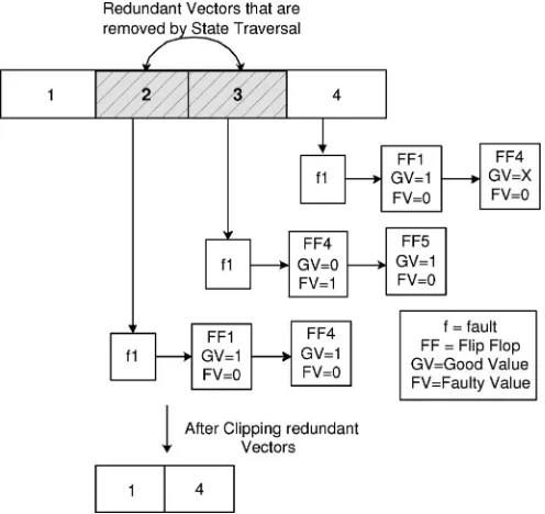
Fig. 1. Compaction by ST algorithm.
Algorithm 3. In Algorithm 3, it is assumed that the restored subse-quenceV, consisting ofnvectors, detectsF faults. It is also assumed that i and j are variables corresponding to time frames i and j, respectively.
Algorithm 3. State Traversal(V, Fn, Ftarget)
1) Leti= 2andj=n. 2)while(j >2){
if((for each faultk∈Fn((Sg/Sf)i⊆(Sg/Sf)j))&
(No fault∈Ftargetdetected in time framesitoj−1)) { Clip vectorsVitoVj−1fromV
j=i−1;i= 2} else if(i < j−1)i+ + else{j− −;i= 2} } // end while 3) Return(V).
For each time framej, the algorithm checks for the earliest possible time frameisuch that the justification requirements of time framej are satisfied by the justification requirements of time framei. If such a time frameiis found, then the vectors fromitoj−1are redundant and can be removed. Algorithm 3 removes these vectors if no fault is detected within these vectors. This heuristic was found experimentally useful in reducing the overall restored test sequence by ST and not resulting in longer test sequences.
Algorithm 3 is illustrated in Fig. 1. As shown in Fig. 1, the algorithm storesSg/Sf for each fault in a list. Because(Sg/Sf)4⊇(Sg/Sf)2
for faultf1, the state requirements at time frame 4 are satisfied by the state requirements at time frame 2. Therefore, test vectors 2 and 3 can be removed from the restored subsequence without affecting the fault coverage. It should be observed that Algorithm 3 takes into account all the faults inFnwhen comparing(Sg/Sf)values. Therefore, the
algorithm removes redundant vectors, just by state comparison, with-out doing any additional fault simulation.
C. Merging Restoration (MR)
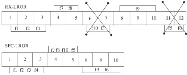
Fig. 2. Compaction by RX-LROR based on increasing fault coverage algorithm.
subsequence and merges it with previously restored subsequences rather than concatenating it. In MR, Step 7) of Algorithm 1 is replaced by first calling Algorithm 4 and then moving back to Step 3). However, in Step 3), the states of flip-flops (Sg/Sf) are not stored for the
undetected faults. Furthermore, the while condition in Step 3) of test restoration algorithm is replaced by only((Sg/Sf)j=X))condition.
Therefore, in Step 5) of MR, test restoration algorithm returns the self-initializing subsequence for the target faults.
Algorithm 4. Merging from Top(C, V)
1) Letncandnvbe the number of test vectors inCandV.
2)if(nc< nv)swapCwithV andncwithnv.
3) Leti=last test vector inC, SM=i 4) Letj=last test vector inV 5)if(i≥1)
while(j≥1andi≥1) {
if(C[i]andV[j]are compatible) {j=j−1;i=i−1; if (i= 0 OR j= 0) Merge C and V, starting from
C[SM]andV[nv]
} // end if
else{ SM=SM−1;i=SM
Go to Step 4)} // breaking the while loop } // end while
6)elseC=V &C; 7) Return(C).
The idea of merging is similar to the one proposed by Royet al.[16]. The subsequences can be merged in different ways. Merging from top is shown by Algorithm 4. It checks the compatibility of the two test sequences (currently restoredV and compacted test setC) and tries to merge the two test sequences starting from the last test vectors of V and C toward the beginning of the test sequences. Merging from bottom, on the other hand, is exactly the opposite; it checks the compatibility of the two test sequencesCandV and tries to merge the two sequences starting from the first test vectors toward the end of the test sequences. Similarly, another scheme uses a more greedy heuristic and decides on merging the subsequence wherever savings are higher. However, experimental results showed that merging from top gave overall best results. Therefore, our work uses merging from top only. ST is not applied in MR as higher compaction is achieved without it.
A drawback of MR, compared with concatenating subsequences (RX-LROR), is that the currently compacted test setC needs to be fault simulated in contrast to fault simulating only the newly restored subsequence.
After a single run of the MR Algorithm, there is a large percentage of unspecified bits. These bits can be randomly filled for subsequent iterations.
D. Subsequence Fault Coverage Increasing LROR (SFC-LROR)
In this section, we propose a modification to the RX-LROR com-paction algorithm (Algorithm 1) to maximize its effectiveness in producing more compacted test sequences.
The proposed algorithm is called SFC-LROR and is shown as Algorithm 5. It follows the same steps as RX-LROR, Algorithm 1, with a difference that after concatenating the newly restored test sequence to the compacted test set, relaxation algorithm [15] is called to return the unspecified input assignments on the currently compacted test set. This step is followed by randomly filling the unspecified inputs. Randomly filling the unspecified inputs is essentially used for increasing the fault coverage as more faults can be detected, which could lead to reducing the number of restored test sequences. These two steps, “relaxation” followed by “random filling,” are done once each time a test sequence is restored, and if the fault coverage of the compacted test sequence increases, the process is repeated.
Algorithm 5. Subsequence Fault Coverage Increasing RX-LROR (SFC-LROR)
1) Fault simulate the circuit using the given test set. Collect the detection time of each fault.
2) Restore the firstktest vectors as a synchronizing sequence from the given test setT.C={v1, v2, v3, . . . , vk}.
3) Fault simulate the restored sequenceC and drop all the faults detected fromFtarget. Store the(Sg/Sf)values of all the
flip-flops for all undetected faults.
4)if(Ftarget=∅)ReturnCelseGo to Step 5).
5) V =Test Restoration(n, Fn), where n is the last time frame
having undetected faults.
6)V =State Traversal(V, Fn, Ftarget)
7)C=C&V;
8)while(fault coverage ofCincreases&Ftarget=∅) { C=Relaxation(C)
RandomFill(C)} 9) Go to Step 3).
It is important to emphasize that the objective of subsequence fault coverage increasing is to achieve higher compaction rather than higher fault coverage by the compacted test sequence. Compaction can increase the overall fault coverage of the test set, which was noted earlier by Guo et al.in PROPTEST [17], [18] for achieving higher fault coverage.
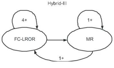
Fig. 3. Hybrid-III scheme.
the faults f5 and f10, and the test sequence (8–10) detects the fault f6, in addition to previously detected faults. Hence, SFC-LROR restores lesser test sequences giving higher level of compaction.
E. HybridSchemes
In this section, we propose three hybrid schemes that reduce the inherent limitation of vector restoration algorithms of quick saturation and capitalize on combining the benefits provided by the different algorithms proposed in this work.
Hybrid-I is composed of two primary steps. In the first step (step-I), the proposed RX-LROR algorithm (Algorithm 1) is run for two iterations, and if there is any reduction in test sequence length in any of these two iterations, the algorithm runs for one more iteration. The algorithm reiterates by running an extra iteration as long as the last iteration reduces the test sequence length. This step is followed by test relaxation [15] and randomly filling the unspecified bits, which forms the second step (step-II) of Hybrid-I. Test relaxation and random filling (step-II) change the composition of test set while maintaining its fault coverage. This helps moving the algorithm out of local minima, and the search space is therefore increased. Furthermore, it allows RX-LROR to reiterate far longer and partially replaces almost every test vector at a very low cost of CPU time. Step-II is again followed by step-I, and the process continues (step-I followed by step-II) until four consecutive iterations are unable to reduce the test size.
Hybrid-II is based on the intuition that merging of relaxed sub-sequences (MR) gives another level of freedom to test compaction; therefore, it may further squeeze the size of test set, if applied after Hybrid-I. As mentioned previously, MR requires comparatively larger number of fault simulations than RX-LROR. This drawback makes it vulnerable to large-sized test set in terms of CPU time.
Hybrid-II is proposed to keep the advantages offered by MR while restricting its limitations. It applies MR to the solution found by Hybrid-I. In this algorithm, MR is applied once and is reiterated until one pass of MR does not further reduce the test size.
Hybrid-III is another powerful compaction scheme, which combines SFC-LROR and MR. The algorithm reiterates SFC-LROR until four consecutive iterations are unable to reduce the test size. This step is followed by MR, which is reiterated until one iteration of MR does not reduce the test size. MR is again followed by SFC-LROR, and the process continues as long as each pass (SFC-LROR followed by MR) reduces the test size. The idea is illustrated by Fig. 3.
III. LIMITATIONS OFJUSTIFICATIONALGORITHM The proposed compaction scheme is based on the test relaxation algorithm in [15], which involves justification of the required values to detect a fault. The justification algorithm has limitations that may lead to the restoration of longer test sequences than necessary.
The justification algorithm is guided by cost functions in case of having several choices for justifying a value. To minimize the length of
the extracted sequence, a multiplicative weight of 10 or 100 is applied to flip-flop cost functions whenever a flip-flop is reached during cost function computation. The approximate nature of the computed cost functions may guide the justification algorithm to a choice that leads to the extraction of a longer test sequence.
Another limitation is during justification of faulty values. Because the justification algorithm is based on the cost of good values only, it may lead to the selection of inferior choices. For instance, to justify 1/0 at the output of a gate, the algorithm considers the cost of justifying 0 as a very high number, as the good value of the gate is 1; it may choose this path only when there is no cheaper choice available or it is the only choice.
This is illustrated in Fig. 4. Suppose that it is required to restore a test subsequence for the faultks-a-0 from the given test sequence (10, 11, 11, 11).
The fault is detected in the last time frame, and justifying the value 1/0 on the output leads to the requirement of 1/0 on linemandX/0 on linen. The faulty value on linemis justified through the fault site, and this leads to the requirement of1/X on input A. There are no justification requirements on input B; and hence, it can be relaxed.
The valueX/0on linen has to be justified in the previous time frame (i.e., time frame 3). This will lead to the justification requirement X/0 on line o in time frame 3. Notice that this value could be justified through linepfrom the fault site leading to the test sequence (XX,1X). However, the algorithm uses cost functions based on good values only; the cost of having a zero on linepis a very high number. Thus, line p is not selected, and line q is selected as it has lesser cost. This causes the algorithm to go back until the first time frame, where the value is justified through input B. Thus, the algorithm will return the test sequence(X0,1X,1X,1X), which has redundant vectors.
One way to address this limitation is by computing the cost of faulty values (in addition to good values) for a single time frame. This could be computed by injecting the faulty values at the fault site and processing the circuit level by level. These two cost functions could better guide the justification process for good and faulty values separately, using respective cost functions. However, this step could be time consuming.
A second and more exact method to address this limitation is by setting an upper limit to the size of restored subsequence. During the justification process, if the restored subsequence reaches that upper limit, it could then be fault simulated using the target fault list. In case of failure in fault detection, the justification algorithm would continue until it justifies the fault or it reaches the upper limit again. In either case, a pass of fault simulation would restrict the size of subsequence. This scheme is a compromise between large test size due to inexact nature of cost functions and expensive vector-by-vector fault simulation to find the exact starting point of the subsequence as used by LROR.
Fig. 4. Limitation of justification algorithm in extraction of longer test sequence.
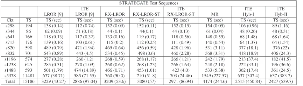
TABLE I
COMPACTIONRESULTS ONSTRATEGATE TESTSEQUENCES
IV. EXPERIMENTALRESULTS
To demonstrate the effectiveness of the proposed test compaction al-gorithms, we have performed experiments on the ISCAS89 benchmark circuits using STRATEGATE [2] and HITEC [19] test sequences. The experiments are conducted on an IBM P-IV 2.0-GHz processor, with 512-MB RAM, and HOPE [20] is used as a fault simulator.
The RX-LROR version implemented in our work is similar to the one proposed by Guoet al.[9], as it does not include new faults into the target fault set during subsequence restoration for a group of faults in a single time frame. Therefore, our implementation of RX-LROR is compared with that proposed by LROR [9] for a fair comparison. This version of LROR [9] used 20 test vectors as synchronizing sequence in case of test size more than 300 vectors and l/16 otherwise. The number of vectors in a synchronizing sequence is kept the same in our version of RX-LROR for the sake of comparison. The proposed hybrid schemes have shown better results and are also compared with the other best known compaction algorithms, i.e., LROR [12], MISC [12], and SIFAR [10], to show their overall performance. It should be noted that LROR [12] uses a single test vector as a synchronizing sequence; therefore, for fair comparison, hybrid schemes and SFC-LROR have also used the same synchronizing sequence in their respective RX-LROR implementations.
During cost function computation for flip-flops, our implementation of RX-LROR, RX-LROR-ST, and test relaxation applies a multi-plicative weight of 10; whereas, in SFC-LROR and MR, it applies a
multiplicative weight of 100. These weights were selected based on experiments.
The performance of compaction algorithms on STARATEGATE [2] test sequences, together with CPU time, reported in brackets are shown in Table I. The results of LROR [9] are compared with the proposed algorithms. From Table I, it can be seen that the proposed RX-LROR performed better than RX-LROR [9] on seven out of ten circuits, with slightly better overall savings and comparable CPU time. These results are further improved by applying ST to the newly restored subsequences in RX-LROR-ST algorithm. RX-LROR-ST has further reduced the compacted test set against a small penalty of CPU time. It has again performed better than LROR [9] on seven out of ten circuits. The next column (ITE-RX-LROR-ST) is the iterative version of the same algorithm. Although it shows comparable results to ITE-LROR [9], it can be noticed that ITE-RX-ITE-LROR-ST has suffered from quick saturation, and for many circuits it is unable to reduce the test size.
It can be observed that for some circuits, e.g., s5378, the compacted test sequence length obtained by our proposed implementation of RX-LROR (Algorithm 1) is larger than the one obtained by LROR [9]. This is due to the current limitations of the justification algorithm, which will be addressed in future work.
[image:6.594.40.557.318.466.2]TABLE II
HYBRID-IIINCOMPARISON TOBESTKNOWNCOMPACTIONALGORITHMS ONSTRATEGATEANDHITEC TESTSEQUENCES
TABLE III
COMPARISON OFRX-LROR-STANDSFC-LRORONSTRATEGATEANDHITEC TESTSEQUENCES
version of RX-LROR). This is due to the fact that the extracted test sequences are not fully specified, which reduces the number of faults detected by the restored sequence compared with the fully specified one. This also results in extracting a larger number of test sequences, which affects the compaction quality and CPU time. Despite these limitations, it has the potential of improving the compaction quality, if applied after RX-LROR, as discussed previously.
Hybrid-I is shown next in Table I. It can be seen that ITE-Hybrid-I has significantly improved the results of ITE-RX-LROR-ST and has performed better than ITE-LROR [9] on nine out of ten circuits, with higher overall savings.
The last column of Table I shows the performance of ITE-Hybrid-II. MR has shown the effect of further squeezing the size of test set, which is already reduced by ITE-Hybrid-I. ITE-Hybrid-II has performed better than ITE-LROR [9] on nine out of ten circuits and has given the highest overall savings, in comparison to all other algorithms shown in Table I.
Based on the above results, Hybrid-II is compared with ITE-LROR [12], ITE-MISC [12], and ITE-SIFAR [10] on STRATEGATE [2] and HITEC test sequences [19] in Table II.
Considering STRATEGATE test sequences [2], it can be seen that ITE-Hybrid-II has performed better on eight out of ten circuits, with higher overall savings than ITE-LROR [12]. When compared with
ITE-SIFAR [10], ITE-Hybrid-II has again performed better on seven out of ten circuits, whereas one resulted in a draw. In terms of overall savings, ITE-Hybrid-II has shown higher savings than ITE-SIFAR. However, ITE-MISC has performed better than ITE-Hybrid-II on six out of ten circuits, but the overall savings are comparable and the CPU time is significantly higher than that of ITE-Hybrid-II.
Next, these algorithms (other than ITE-SIFAR) are compared on HITEC [19] test sequences. As shown in Table II, ITE-Hybrid-II gives better results than ITE-LROR [12] on nine out of thirteen circuits, with significantly higher overall savings. However, comparing to ITE-MISC [12], it shows better performance on nine out of thirteen circuits, with slightly better overall savings and lesser CPU time. The effect of ITE-Hybrid-II is even more pronounced for the circuits s1196, s1238, s3271, s3384, and s4863.
TABLE IV
HYBRID-IIIINCOMPARISON TOBESTKNOWNCOMPACTIONALGORITHMS
out of thirteen circuits and achieved much higher overall savings. It is worth mentioning that this (fault coverage increasing) scheme is generic and can be applied on top of any static compaction scheme. These results demonstrate the strong potential of the scheme.
The performance of the iterative version of SFC-LROR (ITE-SFC-LROR) is shown in Table III. ITE-SFC-LROR reiterates SFC-LROR until four consecutive iterations are unable to reduce the test size. It can be seen that in comparison to SFC-LROR on STRATEGATE test sequences [2], it has further reduced the test size on nine out of ten circuits and achieved higher overall savings of nearly 400 test vectors. Similarly, on HITEC test sequences [19], it has further squeezed the test size on eleven out of thirteen circuits, with nearly 900 test vectors higher overall savings.
ITE-SFC-LROR can also be compared with the other best known compaction algorithms shown in Table II. On STRATEGATE test sequences [2], in comparison to ITE-LROR [12], ITE-SFC-LROR has performed better on eight out of ten circuits, with higher overall savings. In comparison to ITE-SIFAR [10], it has again performed better on six out of ten circuits, with higher overall savings. Finally, in comparison to ITE-MISC [12], it has performed better on four out of ten circuits, with comparable savings. The effect is more pronounced on s5378.
The performance of ITE-SFC-LROR can also be compared with all these algorithms (other than SIFAR [10]) on HITEC test sequences [19] shown in Table II. It can be noticed that ITE-SFC-LROR has performed better than ITE-LROR [12] on ten out of thirteen circuits, whereas one resulted in a draw. It has shown more than 600 test vectors savings than ITE-LROR [12]. In comparison to ITE-MISC [12], it has performed better on eight out of thirteen circuits and achieved almost 200 test vectors savings more than ITE-MISC [12]. Some of the cir-cuits like s713, s820, s1238, s1488, s5378, and s4863 are worth noticing.
Finally, Table IV shows the performance of ITE-Hybrid-III and compares it with the best known compaction algorithms on STRATE-GATE [2] and HITEC [19] test sequences. On STRATESTRATE-GATE test sequences [2], in comparison to ITE-LROR [12], ITE-Hybrid-III has performed better on eight out of ten circuits, with significantly higher overall savings. In comparison to ITE-SIFAR [10], it has again per-formed better on eight out of ten circuits, with higher overall savings. Finally, in comparison to ITE-MISC [12], it has performed better on five out of ten circuits, with higher overall savings. The effect is more pronounced on s1196, s1238, and s5378.
TABLE V
RX-LRORINCOMPARISON TOLRORTODEMONSTRATE
LIMITATIONS OFJUSTIFICATIONALGORITHM
ITE-Hybrid-III is compared next in the same table on HITEC test sequences [19]. It can be noticed that ITE-Hybrid-III has performed better than ITE-LROR [12] on eleven out of thirteen circuits, whereas one resulted in a draw. It has shown more than 1000 test vectors savings than ITE-LROR [12]. In comparison to ITE-MISC [12], it has performed better on twelve out of thirteen circuits and achieved almost 600 test vectors higher overall savings. Some of the circuits like s713, s820, s1196, s1238, s1488, s5378, s3271, s3384, and s4863 have achieved significantly higher savings than the other two algorithms.
The circuits for which RX-LROR resulted in much longer test sequences than LROR [9] are shown in Table V. It should be noted that we have implemented LROR scheme, similar to [9], for ease of com-parison, because [9] did not report results on HITEC test sequences. These circuits are not shown in other tables as they demonstrate lim-itations of justification algorithm either on HITEC or STRATEGATE test sequences. It should be observed that s382, s1423, and s1494 have shown better results than LROR on one of the two (either on HITEC or STRATEGATE) test sets, but are removed from other tables due to much higher test size on the other test sequence. The difference in test size is due to the limitations of the used justification algorithm. Techniques to address these limitations are proposed in Section III and will be further investigated in future work.
ATPG is often used for high-volume manufacturing designs that cannot adopt the full-scan design methodology, e.g., microprocessors. Having more compacted test sequences will reduce the TAT and the overall testing cost.
V. CONCLUSION
In this paper, we have proposed several static compaction algorithms for sequential circuits based on efficient test relaxation and ROR schemes. The proposed work has the advantage of quickly restoring a test sequence for a set of faults compared with vector-by-vector fault-simulation-based restoration techniques. The restored subsequence is further compacted by ST algorithm, which allows the removal of redundant vectors without additional fault simulation. These restored subsequences can be either concatenated (having fully specified bits; making RX-LROR), or they can be subjected to increasing the fault coverage (SFC-LROR) and, finally, can also be merged (relaxed input assignments, MR). MR is found to be more effective after applying RX-LROR and SFC-LROR as demonstrated by ITE-Hybrid-II and ITE-Hybrid-III. Finally, we have also proposed an efficient way of taking any compaction algorithm out of saturation. This is achieved by using test relaxation and randomly filling the unspecified bits before reiterating the algorithm, demonstrated by ITE-Hybrid-I.
The proposed static compaction algorithms in this paper have clearly shown the tradeoffs between compaction quality and CPU time.
ACKNOWLEDGMENT
The authors would like to thank Dr. R. Guo for clarifying some of the concepts of vector restoration and K. Al-Utaibi for his help and support in the test relaxation algorithm.
REFERENCES
[1] T. Marchok, A. El-Maleh, W. Maly, and J. Rajski, “A complexity analysis of sequential ATPG,”IEEE Trans. Comput.-Aided Des. Integr. Circuits Syst., vol. 15, no. 11, pp. 1409–1423, Nov. 1996.
[2] M. S. Hsiao, E. M. Rudnick, and J. H. Patel, “Sequential circuit test generation using dynamic state traversal,” inProc. Eur. Design Test Conf., Mar. 1997, pp. 22–28.
[3] I. Pomeranz and S. M. Reddy, “Vector restoration-based static compaction using random initial omission,”IEEE Trans. Comput.-Aided Des. Integr. Circuits Syst., vol. 23, no. 11, pp. 1587–1592, Nov. 2004.
[4] ——, “A new approach to test generation and test compaction for scan circuits,” inProc. Design Automation Test Eur., 2003, pp. 1000–1005. [5] ——, “Procedures for static compaction of test sequences for synchronous
sequential circuits,”IEEE Trans. Comput., vol. 49, no. 6, pp. 596–607, Jun. 2000.
[6] M. S. Hsiao, E. M. Rudnick, and J. H. Patel, “Fast static compaction algo-rithms for sequential circuit test vectors,”IEEE Trans. Comput., vol. 48, no. 3, pp. 311–322, Mar. 1999.
[7] M. S. Hsiao and S. T. Chakradhar, “State relaxation based subsequence removal for fast static compaction in sequential circuits,” inProc. DATE, Feb. 1998, pp. 577–582.
[8] I. Pomeranz and S. M. Reddy, “Vector restoration based static compaction of test sequences for synchronous sequential circuits,” inProc. Int. Conf. Computer Design, Oct. 1997, pp. 360–365.
[9] R. Guo, I. Pomeranz, and S. M. Reddy, “On speeding-up vector restora-tion based static compacrestora-tion of test sequences for sequential circuits,” in Proc. Asian Test Symp., 1998, pp. 467–471.
[10] X. Lin, W. T. Cheng, I. Pomeranz, and S. M. Reddy, “SIFAR: Static test compaction for synchronous sequential circuits based on single fault restoration,” inProc. IEEE VLSI Test Symp., 2000, pp. 205–212. [11] R. Guo, S. M. Reddy, and I. Pomeranz, “PROPTEST: A property based
test pattern generator for sequential circuits using test compaction,” in Proc. Design Automation Conf., Jun. 1999, pp. 653–659.
[12] ——, “Reverse-order-restoration-based static test compaction for syn-chronous sequential circuits,”IEEE Trans. Comput.-Aided Des. Integr. Circuits Syst., vol. 22, no. 3, pp. 293–304, Mar. 2003.
[13] I. Pomeranz and S. M. Reddy, “Vector replacement to improve static-test compaction for synchronous sequential circuits,”IEEE Trans. Comput.-Aided Des. Integr. Circuits Syst., vol. 20, no. 2, pp. 336–342, Feb. 2001. [14] ——, “Sequence reordering to improve the levels of compaction
achiev-able by static compaction procedures,” inProc. Conf. Design Automation Test Eur., Mar. 2001, pp. 214–218.
[15] A. El-Maleh and K. Al-Utaibi, “An efficient test relaxation technique for synchronous sequential circuits,”IEEE Trans. Comput.-Aided Des. Integr. Circuits Syst., vol. 23, no. 6, pp. 933–940, Jun. 2004.
[16] R. Roy, T. Niermann, J. H. Patel, J. Abraham, and R. Saleh, “Compaction of ATPG-generated test sequences for sequential circuits,” inProc. Int. Conf. Computer-Aided Design, Nov. 1988, pp. 382–385.
[17] I. Pomeranz and S. M. Reddy, “On static compaction of test sequences for synchronous sequential circuits,” inProc. 33rdConf. Design Automation, Jun. 1996, pp. 215–220.
[18] S. M. Reddy, R. Guo, and I. Pomeranz, “PROPTEST: A property-based test generator for synchronous sequential circuits,”IEEE Trans. Comput.-Aided Des. Integr. Circuits Syst., vol. 22, no. 8, pp. 1080–1091, Aug. 2003.
[19] T. M. Niermann and J. H. Patel, “HITEC: A test generation package for sequential circuits,” inProc. EDAC, 1991, pp. 214–218.
[20] H. K. Lee and D. S. Ha, “HOPE: An efficient parallel fault simulator for synchronous sequential circuits,” inProc. Design Automation Conf., Jun. 1992, pp. 336–340.
Exact and Heuristic Approaches to Input Vector Control for Leakage Power Reduction
Feng Gao and John P. Hayes
Abstract—Leakage power consumption is an increasingly serious prob-lem in very large-scale integration circuits, especially for portable appli-cations. Two novel approaches to leakage power minimization in static complementary metal–oxide–semiconductor circuits that employ input vector control (IVC) are investigated. The authors model leakage effects by means of pseudo-Boolean functions. These functions are linearized and incorporated into an exact (optimal) integer linear programming (ILP) model, called virtual-gate ILP, which analyzes leakage variation with respect to a circuit’s input vectors. A heuristic mixed-integer linear pro-gramming (MLP) method is also proposed, which has several advantages: it is faster, its accuracy can be quickly estimated, and tradeoffs between runtime and optimality can easily be made. Furthermore, the MLP model also provides a way to estimate a lower bound on circuit leakage current. The proposed methods are used to generate an extensive set of experimen-tal results on leakage reduction. It is shown that average leakage currents are usually 1.25 times the minimum, confirming the effectiveness of IVC. The heuristic MLP approach is shown to be approximately 13.6 times faster than the exact ILP method, whereas finding input vectors whose power consumption is only a few percent above the optimum. In addition, the lower bound estimated by the MLP model is also within a few percent of the optimal value.
Index Terms—Input vector control, integer linear programming, leak-age current minimization, pseudo-Boolean functions.
I. INTRODUCTION
As CMOS technology evolves, leakage currents are becoming responsible for more and more of a circuit’s overall power con-sumption [10]. This problem is especially serious in portable and
Manuscript received January 25, 2005; revised June 29, 2005. This work was supported by the National Science Foundation under Grant CCR-0073406. This paper was presented at ICCAD 2004. This paper was recommended by Associate Editor M. Pedram.
F. Gao is with Advanced Micro Devices, Inc., Boxborough, MA 01719 USA (e-mail: [email protected]).
J. P. Hayes is with the Advanced Computer Architecture Laboratory, Univer-sity of Michigan, Ann Arbor, MI 48109 USA (e-mail: [email protected]).
Digital Object Identifier 10.1109/TCAD.2006.875711