DESIGN AN ANALYSIS OF OPTIMUM CLEARANCE OF
AN OPEN SMALL THIMBLE BLANKING DIE
MASYHADI BIN AZEMIN
B051310338
UNIVERSITI TEKNIKAL MALAYSIA MELAKA
UNIVERSITI TEKNIKAL MALAYSIA MELAKA
DESIGN AND ANALYSIS OF OPTIMUM CLEARANCE OF AN
OPEN SMALL THIMBLE BLANKING DIE
This report submitted in accordance with requirement of the Universiti Teknikal Malaysia Melaka (UTeM) for the Bachelor Degree of Manufacturing Engineering
(Manufacturing Design) (Hons.)
by
MASYHADI BIN AZEMIN
B051310338
920902-03-5395
UNIVERSITI TEKNIKAL MALAYSIA MELAKA
BORANG PENGESAHAN STATUS LAPORAN PROJEK SARJANA MUDA
TAJUK: DESIGN AND ANALYSIS OF OPTIMUM CLEARANCE OF AN OPEN SMALL THIMBLE BLANKING DIE
SESI PENGAJIAN: 2015/16
Saya MASYHADI BIN AZEMIN
mengaku membenarkan Laporan PSM ini disimpan di Perpustakaan Universiti
Teknikal Malaysia Melaka (UTeM) dengan syarat-syarat kegunaan seperti berikut:
1. Laporan PSM adalah hak milik Universiti Teknikal Malaysia Melaka dan penulis. 2. Perpustakaan Universiti Teknikal Malaysia Melaka dibenarkan membuat salinan
untuk tujuan pengajian sahaja dengan izin penulis.
3. Perpustakaan dibenarkan membuat salinan laporan PSM ini sebagai bahan pertukaran antara institusi pengajian tinggi.
4. **Sila tandakan ( )
SULIT
TERHAD
TIDAK TERHAD
(Mengandungi maklumat yang berdarjah keselamatan atau kepentingan Malaysia sebagaimana yang termaktub dalam AKTA RAHSIA RASMI 1972)
(Mengandungi maklumat TERHAD yang telah ditentukan oleh organisasi/badan di mana penyelidikan dijalankan)
Alamat Tetap:
No 116 Jalan Masjid, Kg Ulu Kusial
17500 Tanah Merah,
Kelantan.
Tarikh: ________________________
Disahkan oleh:
Cop Rasmi:
Tarikh: _______________________
DECLARATION
I hereby, declared this report entitled “Design An Analysis Of Optimum Clearance Of An Open Small Thimble Blanking Die” is the results of my own research except
as cited in references.
Signature :
Author’s Name : MASYHADI BIN AZEMIN
APPROVAL
This report is submitted to the Faculty of Manufacturing Engineering of UTeM as a partial fulfillment of the requirements for the degree of Bachelor of Manufacturing Engineering (Manufacturing Design) (Hons.). The member of the supervisory is as follow:
i
ABSTRAK
ii
ABSTRACT
iii
DEDICATION
iv
ACKNOWLEDGEMENTS
v
TABLE OF CONTENT
Abstrak i
Abstract ii
Dedication iii
Acknowledgement iv
Table of Content v
List of Tables ix
List of Figures x
CHAPTER 1: INTRODUCTION 1
1.1 Background of Project 1
1.2 Problem Statement 2
1.3 Objective 2
1.4 Scope 3
CHAPTER 2: LITERATURE REVIEW 4
2.1 Sheet Metal Work 4
2.2 Manual Sheet Work 4
2.3 Metal Stamping 5
2.3.1 Coining 5
2.3.2 Bend Forming 6
2.3.3 Draw Forming 6
2.3.4 Deep Draw Forming 7
2.3.5 Blanking 8
2.4 Classifications of Dies and Application 8
2.4.1 Single Operations Dies 9
2.4.2 Compound Dies 9
2.4.3 Progressive Dies 10
2.4.4 Transfer Dies 11
2.4.5 Multi-slide, Four-slide, Wire Form Dies 12
2.5 Part of Blanking Die 14
vi
2.5.2 The Die Block 15
2.5.3 The Blanking Punch 15
2.5.4 Piercing Punch 16
2.5.5 Punch Plate 16
2.5.6 Pilot 17
2.5.7 The Back Gage 17
2.5.8 The Finger Stops 18
2.5.9 Automatic Stop 18
2.5.10 Stripper Plate 19
2.5.11 Fasteners 19
2.6 Fourteen Steps To Design a die 20
2.6.1 The Scrap Strip (Step 1) 20
2.6.2 The Die Block (Step 2) 21
2.6.3 The Blanking Punch (Step 3) 22
2.6.4 Piercing Punches (Step 4) 23
2.6.5 The Punch Plate (Step 5) 23
2.6.6 Pilots (Step 6) 24
2.6.7 Gages (Step 7) 24
2.6.8 The Finger Stop Finger (Step 8) 25
2.6.9 The Automatic Stop (Step 9) 26
2.6.10 The Stripper (Step 10) 26
2.6.11 Fasteners (Step 11) 27
2.6.12 The Die Set (Step 12) 28
2.6.13 Dimensions and Notes (Step 13) 29
2.6.14 Bill of Material (Step 14) 30
2.7 Characteristics of Metal in Sheet Forming 31
2.8 Blanking force 32
2.9 Area to Be Cut 33
2.10 Blanking Die of Thimble Open Small 35
2.11 Blanking Die Parameters of Thimble Open Small Die 36
2.12 Shear Stress 37
2.13 Normal Stress 37
vii
CHAPTER 3: METHODOLOGY 39
3.1 Flow Chart 39
3.1.1 Phase 1: Planning 41
3.1.2 Phase 2: Concept Development 41
3.1.3 Phase 3: Detail Design 41
3.1.4 Phase 4: Analysis & Refinement 42
3.1.5 Phase 5: Report Submission & Presentation 42
3.2 Process to produce thimble open small 42
3.3 Concept Generation 44
3.3.1 Blanking concept Generation 44
3.4 Concept Selection 46
3.5 Workpiece 47
3.6 3D-Modeling 47
3.7 Punch Force 48
3.8 FEA Simulation 49
3.9 Expected Result 51
CHAPTER 4 : PROCEDURE OF SOLIDWORKS DRAWING
AND EXPLICIT DYNAMIC ANALYSIS 52
4.1 Procedure 3D Modelling 52
4.1.1 Upper Die
4.1.2 Raw Material 57
4.1.3 Spring Giude 58
4.1.4 Spring 59
4.1.5 Lower Die 60
4.2 Assembly of Blanking Die 62
4.3 Create Analysis System 63
4.4 Engineer Data 66
4.5 Geometry 67
4.6 Define Connections 68
viii
4.7 Meshing 70
4.8 Establish Analysis Setting 70
4.9 Fixed Support 71
4.10 Displacement 71
4.11 Solve 72
4.12 Review Result 72
CHAPTER 5 : RESULT AND DISCUSSION 75
5.1 Result of Tensile Test 75
5.2 Result for Each Conceptual Design 78
5.2.1 Displacement parameter 78
5.2.2 Blanking Analysis 80
5.2.2.1 Conceptual Design A 80
5.2.2.2 Conceptual Design B 83
5.2.2.3 Conceptual Design C 86
5.2.2.4 Conceptual Design D 88
5.2.2.5 Conceptual Design E 92
5.2.2.6 Summary result of total deformation for blanking analysis 97 2.2.2.7 Summary result of shear stress for blanking analysis 97 5.2.2.8 Summary result of structure for blanking analysis 98
5.3 Propose Design for Blanking Die 99
CHAPTER 6 : CONCLUSION 99
6.1 Conclusion 99
6.2 Recommendation 100
6.3 Sustainability 100
ix
LIST OF TABLES
2.7 Characteristics of Metal in Sheet Forming 31
2.8 Shear Strength for Various Materials 33
5.1 Dimensions involved in ASTM-D638 standard 76
5.2 Result obtained for tensile test sample 76
5.3 Standard tabular data of displacement 77
5.4 Result of tensile test of sample 79
5.5 Content of Blanking Analysis 80
5.6 Total deformation in a form of tabular of conceptual design A 80 5.7 Shear stress for blanking analysis of conceptual design A 82 5.8 Total deformation in a form of tabular of conceptual design B 83 5.9 Shear stress for blanking analysis of conceptual design B 84 5.10 Total deformation in a form of tabular of conceptual design C 86 5.11 Shear stress for blanking analysis of conceptual design C 87 5.12 Total deformation in a form of tabular of conceptual design D 89 5.13 Shear stress for blanking analysis of conceptual design D 90 5.14 Total deformation in a form of tabular of conceptual design E 92 5.15 Shear stress for blanking analysis of conceptual design E 94
5.16 Analysis of depth of cut 95
5.17 Analysis maximum shear stress versus time 96
5.18 Structural result of blanking analysis 97
x
LISTS OF FIGURES
1.1 The Defect Burr 2
2.1 Coining Die and product 5
2.2 Die Forming 6
2.3 Draw Forming 7
2.4 Deep Draw Forming 7
2.5 Blanking Die 8
2.6 Single Operations Dies 9
2.7 Compound Die 10
2.8 Example of Progressive Die 11
2.9 Transfer Die 12
2.10 Four-slide Die 13
2.11 Part of Blanking Die 14
2.12 Die Set 14
2.13 The Die Block 15
2.14 The Blanking Punch 15
2.15 Piercing Punch 16
2.16 Punch Plate 16
2.17 A Pilot 17
2.18 The Back Gage 18
2.19 A Finger Stops 18
2.20 Automatic Stop 19
2.21 Stripper Plate 19
2.22 Fasteners 20
xi 2.30 View of the assembly with the finger stop added 25 2.31 View of the assembly with the automatic stop added 26 2.32 View of the assembly with the stripper added 27 2.33 View of the assembly with fasteners added 28
2.34 View of the assembly including die set 29
2.35 View of the complete die with dimension and notes 29 2.36 The complete die drawing, including the bill of material 30 2.37 Drawing that illustrates area subjected to shear. 34 2.38 Drawing that illustrates area subjected to shear in blanking 34
2.39 Variable and Feature of Blanking Die 36
2.40 Variable in blanking die 36
2.41 Shear Stress cross section 37
2.42 Bar in tension and compresson stress 37
3.1 Flow chart of PSM I and PSM II 40
3.2 Flow chart making thimble open small 43
3.3 Concept Design 44
3.3a Concept A with clearance 0.00 45
3.3b Concept B with clearance 0.05 45
3.3c Concept C with clearance 0.10 45
3.3d Concept D with clearance 0.20 46
3.3e Concept D with clearance 0.30 46
3.4 Workpiece 47
3.5 Flow of 3D modelling for thimble open small 48 3. 6 FEA Simulation using Explicit Dynamic Analysis in ANSYS software 50
4.1 Starting 3D Modelling 53
4.2 The sketch in drawing 53
4.3 Sketch a rectangle 54
4.4 Extrude boss 1 54
4.5 Sketch of shape 55
4.6 Extrude Boss 2 55
4.7 Position of circle 55
4.8 Extrude cut 56
xii
4.10 Upper die after fillet 56
4.11 Sketch of rectangle 57
4.12 Extrude boss 57
4.13 Extrude boss of circle 58
4.14 Position of circle 58
4.15 Extrude boss of circle 59
4.16 Variable pitch of spring 59
4.17 Profile and path 60
4.18 Extrude boss 1 61
4.19 Sketch of shape 61
4.20 Extrude cut 1 61
4.21 Sketch of shape 62
4.22 Extrude cut 2 62
4.23 The assembly design of the blanking 62
4.24 The process flow of the Explicit Dynamics Procedure 63
4.25 The project schematic in ANSYS 64
4.26 Engineering data cell 64
4.27 Import Geometry to attach 65
4.28 Mesh the geometry model 65
4.29 Engineering data 66
4.30 Geometry object 67
4.31 Contact region setting 69
4.32 Fractional automatically contact setting 69
4.33 Analysis settings 70
4.34 Fixed support choosen 71
4.35 Displacement setting 72
4.36 The result in Mechanical Application 73
4.37 Result of total deformation in a form of analysis structure 73
4.38 Graph displacement versus time 74
5.1 ASTM D-638 standard 76
5.2 Graph of stress versus stroke strain for sample 77
5.3 Graph displacement versus time 79
xiii 5.5 Graph displacement versus time for conceptual A. 81
5.6 Structure analysis for conceptual A. 81
5.7 Graph Shear stress displacement versus time for conceptual A 82 5.8 Shear stress in a form of structure analysis for conceptual A 82 5.9 Graph displacement versus time for conceptual B 83
5.10 Structure analysis for conceptual B 84
1
CHAPTER 1
INTRODUCTION
This chapter describes the introduction about blanking die for producing the thimble open small. In this part, begin with the introduction of the background, followed by translation of problem statement objectives, scope, and structure of the research are discussed.
1.1 Background of Study
Nowadays, demand for open small thimble has increased in the electric company especially in Tenaga Nasional Berhad (TNB). Thimble used to form the eye of the loop before the rope is secured. Steel thimbles, offer added protection from wear and tear of direct contact and deformation of the eye, extending the service life of the wire rope or wire rope sling.
Blanking die is a one method used for a shaping an open small thimble. The concept of blanking is a cutting process in which a piece of sheet metal is removed from a larger piece of stock by applying a great enough shearing force.
2 the plate into the U shape and bending from plate into the V shape. All the concept and process to making thimble open small are analyzing in this project.
1.2 Problem Statement
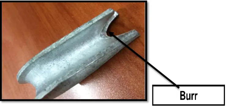
[image:23.595.136.509.346.520.2]There are few problems occurred that affect the product like tear and burr after producing large volume of thimble open small. Figure 1.1 show the burr defect. If the defect always occurred, the daily productivity cannot achieve the target demand. It take some time to rework and the cycle time is increased. At the same time, the cost of the productivity of production will increased.
Figure 1.1 : The Defect Burr
1.3 Objectives
The objectives of this research are:
(a) To redesign the blanking die for thimble open small.
3 1.4 Scope