Review Article
Recent Developments in Multiscale and Multiphase Modelling of
the Hydraulic Fracturing Process
Yong Sheng,
1Marina Sousani,
1,2Derek Ingham,
2and Mohamed Pourkashanian
21School of Civil Engineering, University of Leeds, Leeds LS2 9JT, UK
2Energy Technology and Innovation Initiative (ETII), University of Leeds, Leeds LS2 9JT, UK
Correspondence should be addressed to Yong Sheng; [email protected]
Received 9 December 2014; Revised 6 July 2015; Accepted 12 July 2015
Academic Editor: Xiaoying Zhuang
Copyright © 2015 Yong Sheng et al. This is an open access article distributed under the Creative Commons Attribution License, which permits unrestricted use, distribution, and reproduction in any medium, provided the original work is properly cited.
Recently hydraulic fracturing of rocks has received much attention not only for its economic importance but also for its potential environmental impact. The hydraulically fracturing technique has been widely used in the oil (EOR) and gas (EGR) industries, especially in the USA, to extract more oil/gas through the deep rock formations. Also there have been increasing interests in utilising the hydraulic fracturing technique in geological storage of CO2 in recent years. In all cases, the design and implementation of the hydraulic fracturing process play a central role, highlighting the significance of research and development of this technique. However, the uncertainty behind the fracking mechanism has triggered public debates regarding the possible effect of this technique on human health and the environment. This has presented new challenges in the study of the hydraulic fracturing process. This paper describes the hydraulic fracturing mechanism and provides an overview of past and recent developments of the research performed towards better understandings of the hydraulic fracturing and its potential impacts, with particular emphasis on the development of modelling techniques and their implementation on the hydraulic fracturing.
1. Introduction
Hydraulic fracturing, or fracking, is a technique used in the mining industry and involves the controlled cracking of the rock formation with the use of high pressure liquid
fluids [1]. The technique of hydraulically fracturing the rocks
has been well known since it has been widely used for Enhanced Oil Recovery (EOR) and Enhanced Gas Recovery (EGR) in the oil and gas industries, especially in the USA, to extract more oil/gas through the deep rock formations
[2, 3]. Hydraulic fracturing is a combination of processes,
such as the deformation of the formation due to an external mechanical load (i.e., fluid pressure), the fluid flow through preexisting cracks of the formation, and the propagation of
cracks [4,5]. While the technology behind these processes
has been used for more than 30 years in the name of energy exploitation, underground formations constitute a complex system of variables (both rock and well properties) that are not fully understood and thus are still under investigation
[6,7].
Scientists over the years have concluded that there is a
clear relationship between the increase of CO2 and human
activities [8–10]. Overpopulation and therefore extensive
industrial activities contribute greatly to the increase of greenhouse gas emissions and countries have agreed to
a common mitigation plan in order to reduce the CO2
emissions to acceptable levels and achieve a low carbon
energy future [9,11–14]. Carbon Capture and Storage (CCS) is
a promising method that plays a central role as part of the
mit-igation plan [10,15–18]. CCS is a five-step procedure which
embraces all stages of industrial production [19]. Specifically,
it involves the capture of high amounts of CO2 produced
from industrial facilities before they are released into the atmosphere, its liquefaction and pipeline transport into the site (oil and gas reservoirs, saline formations), injection under high pressure, and storage in deep underground formations [20].Figure 1illustrates all stages of the CCS technology from capture until storage. The hydraulic fracturing technique on porous media has become part of the injection and
storage stage of CCS [1, 21] and therefore it is essential to
CO2injection at a rig
Saline aquifer
Gas field
Caprock
Caprock
CO2is piped offshore
CO2injection under
pressure via a well into the storage site
CO2
CO2captured at the power plant
Compression
Oil
Enhanced Oil
Increasing temperature and pressure
[image:2.600.102.500.73.306.2]Recovery (EOR) field
Figure 1: Schematic of CCS infrastructure showing the five steps of the technology and the geological media of storage [137].
understand the mechanisms that involve permanent storage
and reduction of CO2.
The economic benefits from energy exploitation and especially the extraction of natural gas from shale gas for-mations through hydraulic fracturing methods are estimated to be considerable. The USA has already moved towards extensive shale gas exploitation, making Europe the next one to follow in the search of energy production and economy growth. Specifically, in the UK there are some promising estimations of the amount of shale gas from numerous formations throughout the nation. According to the British Geological Survey (BGS) and the Department of Energy and Climate Change (DECC), the Bowland Shale formation is estimated to contain about 1300 trillion cubic feet of shale
gas, with about 10 per cent recoverable [22]. The scenario
for UK shale gas production looks to be more encouraging, according to the Institute of Directors (IoD), suggesting
high investments and numerous jobs [23], while suggesting
considerable reductions of imported gas (around 37 per cent) in terms of consumption until 2030, which may lead to further reductions of the import costs, assisting towards a
more balanced economy and energy security [24]. However,
it is important to add that the economic implications are under speculation since they are based mostly on estimations, inferred from the US experience, and not on actual produc-tion.
2. Enhanced Oil and Gas Recovery
Enhanced Oil Recovery (EOR) and/or Enhanced Gas Recov-ery (EGR) is regarded as the most effective schemes for a
low carbon energy future, since CO2 injection and oil/gas
extraction from hydrocarbon reservoirs can be performed
concurrently [25]. During this process, fluids are injected
under high pressure into porous formations, with the aim of
storing the liquefied CO2under an impermeable caprock, and
cause controlled cracking to improve reservoir productivity [7].Figure 2 illustrates a hydraulic fracturing technique in a shale gas formation, where the fracturing fluid is injected within the shale under high injection pressure to reactivate or open new fractures into the formation. The fractures stay open with the use of shale proppants (sand or ceramics) so
that the shale gas can travel towards the well [26].
Between the two methods, EGR is relatively new and is still under investigation. The main reason is the concerns for degrading gas production due to the mixture between the
initial gas in place and the injected CO2 [27]. Furthermore,
ongoing research aims to provide further insight into such matters, focusing on investigating the factors that affect the process of EGR and storage. Such an example is the
work by Khan et al. [28], who replicated a 3-dimensional
reservoir sandstone model using actual experimental data
and simulated an EGR process, while sequestrating CO2.
Their findings refer to that one specific reservoir and can
confirm that the CO2 injection is applicable in increasing
natural gas recovery and storing high amounts of CO2 at
the same time. The conventional procedure of oil extraction involves the injection of water; however, a large amount of oil stays trapped within the pores of the formation (about 50 per cent) after the primary production, and further recovery can
be achieved by injecting liquefied carbon dioxide [29]. The
latter exists in a supercritical state (dense phase fluid), with reduced viscosity (0.04–0.08 Cp) and surface tension, which
means that the vapour and liquid forms of the CO2coexist.
The component acts like a gas and a compressible fluid at the same time and can take the shape of its vessel, while
having a density (about 600–800 kg/m3) like a fluid [27]. This
Well
Well Sand keeps
fractures open
Shale gas flows from fractures into well
Fracture
Fractures Mixture of water, sand, and chemical
additives
[image:3.600.130.472.74.374.2]Shale
Figure 2: Schematic of the hydraulic fracturing technique in a shale gas formation [138].
pressures beyond 7.38 MPa, and temperatures higher than
31∘C, respectively [25]. Due to the dense phase and the fact
that it is easily miscible with other oils, it gives the CO2great
potential to dissolve and relocate the oil in the reservoir. This technique is a key technology to reduce the anthropogenic emissions produced from overpopulated regions, such as China, while satisfying the extensive demands on electricity
[30]. Although hydraulic fracturing is part of the technology
used for gas/oil extraction, and thus widely used, it is still lacking the development of appropriate regulations for environmental safety and sustainability.
3. Hazards in Hydraulic Fracturing
Regardless of the choice of liquid (water or liquefied CO2), the
hydraulic fracturing process requires the use of a considerable fluid pressure in order to introduce the liquid into the rock formation, until it exceeds the overall strength of the
rock (both compressive and tensile) [31]. Therefore, valid
estimates of the mechanical behaviour of the rock material under intense injection conditions are crucial to the efficient planning and operation of hydrocarbon reservoirs. This constant increase in the fluid pressure during injection causes redistribution of the in situ effective stresses within the reservoir. Although in this process the controlled fracturing of the reservoir is desirable, such stress changes may induce irreversible effects into the rock strata, thus causing possible reactivation of the existing faults. Moreover, the effects of
active faults on the process of leakage are an area where more research has to be performed; scientists generally suggest that the existence of seismogenic faults affects the permeability
structure of the zone enhancing fluid transport [32]. In
the process of hydraulic fracturing, the latter may lead to
possible leakage of liquefied CO2 [33] or flowback water,
thus resulting in potential hazards. Moving towards a bigger picture, the major effects are the possible contamination of shallow groundwater layers by the migration of the toxic components of the flowback fluids as well as the leakage of methane, which acts as a greenhouse gas, into the atmosphere
[34].
3.1. Flowback Fluid. Flowback fluid is the recovered
during transport and the concentration/handling of the
possible hazardous substances [35]. Currently, the issue of
potential implications on the quality of water is a matter of debate. This is due to lack of available information on the composition of the chemicals used in hydraulic fracturing procedures, and therefore scientists focus on this part of research aiming to shed more light. Recent studies are dealing with the ecotoxicological assessment of undiluted fracturing fluids, which indicate a hazardous effect on aquatic life. These studies are based on component-based prognostic models rather than measuring the ecotoxicological effect of a
fracturing fluid as a whole [36]. This provides better accuracy
of the overall results, allowing the prognosis of the effect of the mixture components individually. Generally, flowback fluids contain a mixture of hydraulic fracturing fluid and formation water. The potency of flowback fluid depends on the mix ratio of the formation water and fracturing fluid and although a high proportion of the fracturing fluid may be retained in the formation there is a high tendency for flowback to take place as a result of imposed fracturing
operations [37]. At present, very limited studies have dealt
with the chemical composition of flowback or its potential pollutants, and there are no studies investigating the differ-ence in fracturing fluid from formation water that contains no fracturing fluid in flowback. The work performed by Olsson
et al. [37] aims to bridge the knowledge gap by analysing
the composition and volumes of flowback from different sites in Germany. This research has revealed that no single technology can meet the criteria for the overall treatment of flowback; thus they categorized the flowback fluid into groups and suggested some treatment methods. Furthermore, the accidental penetration of the fracturing and flowback fluids into the water aquifers and their impact on the human-health becomes critical and has been addressed recently. Such an
example is the work by Gordalla et al. [35] who focused on
the assessment of the ingredients of the fracturing fluids on the human-toxicological point of view, the influence of the flowback, and the possible hazards of freshwater reserves and suggested methods for minimising the environmental impact. Moreover, apart from the importance of extending the available information on the chemical composition of fracturing fluids or the environmental impact of the flowback and its proposed treating methods, it is of equal importance to investigate the underground formations and their interaction with the potential migrating fracturing fluids or methane.
Such an example is the work by Lange et al. [38] who aimed to
identify fault zones as preferential pathways that facilitate the movement of fracturing fluids/methane in unconventional gas reservoirs and analysed the effectiveness of the different layers of overburden.
3.2. Risk of Contaminated Aquifers. The extensive use of
unconventional fracking (horizontal drilling and high vol-ume hydraulic fracturing), especially in the USA, has trig-gered a public debate regarding possible health issues related to drinking water. Although industry claims that shale gas fracking is safe with minimum environmental impacts, the European Commission states that the extraction of uncon-ventional hydrocarbons (shale gas) generally imposes a larger
environmental footprint than conventional gas extraction
[39]. Risks from ongoing operations may include surface
and groundwater contamination, water resource depletion, air and noise emissions, land take, disturbance to bio-diversity, and impacts related to traffic. People’s concern, especially in European countries where groundwater is their main resource of drinking water, has forced countries to seek expert opinion. A typical example is Germany and
the ExxonMobil initiative [40]. The latter has formed a
multidisciplinary working group in order to identify the possible environmental risks for the Lower Saxony Basin. Their main task is to assess the available technology (drilling and technical processes) and develop a strategy that fits the requirements for safe hydraulic fracturing operations. Part of this assessment is the “information and dialogue process on hydraulic fracturing,” focusing on the characterization of the hydrogeological system, the chemical reactions under which leakage may occur, the possible leakage pathways, and the
development of suitable models and their results [34,38].
4. Modelling of Rock Fragmentation and
Fluid Flow Problems
Moreover, the rapid growth in computer power and mod-elling has resulted in the development of a large number of software packages used for the numerical analysis of complex engineering problems, such as the identification of problematic (low bond strength) material parameters in
masonry structures [41]. The reason for this is that it is
very difficult for the analytical modelling to measure and describe accurately the complicated problems associated with fracturing. In subsurface investigations in particular, where heterogeneity and a wide range of complex inner mechanisms coexist, numerical modelling is necessary to represent real life scenarios. Numerous mathematical solutions have been applied to look, for example, into the critical mechanical parameters, such as the stress envelope, the porosity and permeability of the material and the effect of layering within the rock, or the way that these are influenced by the
external mechanical load [42]. However, studies that employ
modelling and simulation of rocks at the microscale [43–
45] are fewer and their focus on the complex interplay
between the microproperties and their corresponding effect on the material’s behaviour during the calibration procedure provides at best a general guidance. Therefore, a review on the micro-meso-level modelling using Discrete Element Method is first provided in this section to highlight the research progress in recent years in this area, followed by the broader overview of multiscale and multiphase coupling models.
4.1. Discrete Element Methodology. The DEM is an alternative
approach, to the Finite Element Method (FEM), which aims to describe the macroscopic mechanical behaviour of mate-rials as a result of the interaction of its constitutive individual elements. Specifically, in DEM the material is described as a discontinuum, consisting of numerous distinct particles which represents the inhomogeneities within the material
(joints and/or fractures) in the particle scale [45,46]. Initially
behaviour of soils and sands (noncohesive materials) [47]. The transition from the aforementioned modelling to the one that simulates the micromechanical behaviour of solid rocks is commonly known as the bonded particle model (BPM)
for rock [45]. In a BPM, the breakage of interparticle bonds
simulates the nucleation of a microcrack, while microcrack-ing is achieved by coalescence of multiple bond breakages. The DEM methodology and the particle-based models have been employed in several computer packages in the field of rock mechanics, such as the particle flow code (PFC), the YADE, the universal distinct element code (UDEC), and the discontinuous deformation analysis (DDA).
The advantages of the DEM methods over other tra-ditional techniques, such as the Finite Element Method (FEM), are the simpler representation of the geometries of real rocks, which contain discontinuities, the easier sim-ulation of complex engineering problems without the use of complicated constitutive equations, and thus provide statistically more accurate results. Conversely, the increased simplification requires extensive experimental validation to verify the numerical results of the method and proves that the microscopic models can produce equivalent macroscopic behaviour of real rocks. Finally, the increased computational time due to the nature of the DEM approach (solving the governing equations for a large volume of particles) is another limitation that researchers have to tackle.
4.1.1. Particle Flow Code (PFC). Each of these approaches is
based on the DEMs governing formulations, which include the calculation of the relative motion of the discrete elements, such as slip, rotation, or even complete detachment. More specifically in PFC each particle’s motion is calculated by the equation of motion, given by
𝐹𝑖+ 𝐹𝑖𝑑={{
{
𝑚 ̈𝑥𝑖, for𝑖 = 1, 2, 3,
̇
𝐼𝜔(𝑖−3), for𝑖 = 4, 5, 6,
(1)
where𝐹𝑖is the generalized force which includes the
gravita-tional force,𝐹𝑖𝑑is the damping force,𝑚is the particle’s mass,
̈𝑥
𝑖is the particle’s translational acceleration,𝐼is the moment
of inertia, and ̇𝜔is the angular acceleration.
For the cases where the virtual particles are connected with bonds (reproducing the cementation between grains in real rocks), the updated body forces and moments, due to the presence of bonds, are calculated via the force displacement law:
𝐹𝑖𝑇= 𝐹𝑖𝑛+ 𝐹𝑖𝑠,
𝑀𝑇𝑖 = 𝑀𝑖𝑛+ 𝑀𝑖𝑠, (2)
where𝐹𝑖𝑇,𝑀𝑖𝑇are the total force and moment vectors and
𝐹𝑛
𝑖, 𝐹𝑖𝑠, 𝑀𝑛𝑖, and 𝑀𝑠𝑖 are the axial and shear components
with respect to the contact plane, respectively. Details on the PFC calculation cycle based on the DEM can be found
in Sousani et al. [48]. However each approach has its
own limitations. The PFC utilises the BPM model, since the parallel bond rock modelling has been widely used
to simulate the fracturing mechanism in brittle rocks, but previous versions had the disadvantage of unrealistic ratios between the obtained tensile and unconfined compressive strength, to low nonlinear failure envelopes in terms of triaxial tests, or the problematic modelling of the interfaces
due to the inherent roughness of the interface surfaces [49].
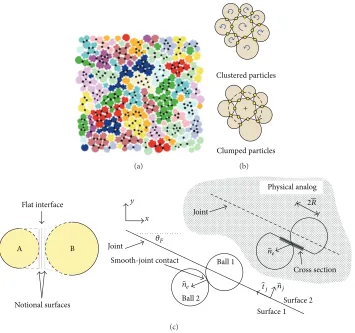
To tackle these limitations of PFC, a number of enhancement measures have been developed with the aim of providing a more accurate nonlinear mechanical behaviour, strength ratios, and friction coefficients. The basic concepts include the “cluster logic” (bonded particles packed together to form angular shapes or blocks that resemble natural grain
struc-tures,Figure 3(a)), performed by Potyondy and Cundall [45],
the “clump logic” (bonded particles that behave collectively
as a single unbreakable rigid body,Figure 3(b)) from Cho et
al. [50], the flat-joint contact model (a more efficient contact
formulation, where disk-shaped particle contacts simulate a finite-length interface that has relative rotation, even upon
bond breakage,Figure 3(c)) from Potyondy [51], and finally
the smooth-joint contact model (SJM) and the synthetic rock
mass approach (SRM), respectively, from Mas Ivars [52,53].
The SJM model simulates the behaviour of an interface disregarding the particle contact orientations locally along-side the interface, while the SRM model is a combination between the BPM and the SJM models that describes the mechanical behaviour of jointed rock masses, including anisotropy, brittleness, and scaling effects which cannot be achieved by empirical methods.
4.1.2. Open-Source Software YADE. Recently, another
par-ticle-based code has been developed, called YADE, as an alternative approach to the well-known commercial PFC
code as previously described [54, 55]. YADE aims to be
more flexible by adding new modelling capabilities, several simulation methods (e.g., DEM, FEM, and Lattice Geo-metrical Model (LGM)) can be coupled within the same framework and also the scientific community can provide direct feedback for improvement of the code with the use of an open-source platform. The fundamental principles of YADE are similar to those of PFC with respect to small defor-mations and fracturing (linear elastic interparticle forces and bond breakage, resp.) but new features, simulating rock discontinuities and ensuring frictional behaviour regardless of the inherent roughness, have been implemented as an
alternative approach to the SJM and SRM models [56]. In
addition, the use of YADE in studying the failure of brittle rocks has led to the creation of additional features, such as the interaction range coefficient, which helps to accurately simulate high ratios of compressive to tensile strengths as well
as nonlinear failure envelopes [57]. However, YADE as well
as many of the open-source software packages appear to be inefficient when compared to commercial software such as PFC, mainly due to the complexity of the user’s interface and the lack of user defined functions. Moreover, open-source software solutions tend to develop mainly in line with specific purposes and also rely on the pool of open resources to help to discover errors and bugs. Some applications of the YADE code include three-dimensional simulations of the
(a)
Clustered particles
Clumped particles +
(b)
2R
A B
Flat interface
Notional surfaces
Physical analog
Joint
Smooth-joint contact Ball 1
Ball 2
Surface1
Surface2
Cross section
̂ne
̂nj
̂tj
̂ne
y x
𝜃F
Joint
[image:6.600.124.479.70.403.2](c)
Figure 3: Developments on the BPM model for better representation of the nonlinear behaviour of hard rock and more realistic values of the ratio between tensile and unconfined compressive strengths. (a) The “cluster” logic [45], (b) the “clump” logic versus the “cluster” logic [50], (c) the flat-joint contact model [51], and smooth-joint contact model (SJM) [139].
effect of preexisting fractures of the brittle materials, under
triaxial loading, on their mechanical behaviour [58, 59]. In
the aforementioned simulations the open-source code YADE has been collaborated with the Discrete Fracture Network (DFN) in order to model the three-dimensional structure of the discrete features.
4.1.3. Universal Distinct Element Code (UDEC). Another type
of modelling, which is based on the DEM equations, is the UDEC, employed to study rock masses that contain
numerous fractures [60, 61]. The computational domain in
UDEC is quantized into blocks using a finite number of intersecting discontinuities and each block is discretized with the use of a finite difference scheme in order to calculate stresses, strains, and deformation. The basic limitation of this technique was the fact that the failure mechanism in rocks was described either through plastic yielding or through deformation of preexisting fractures. Therefore new fractures could not be modelled and hence fracturing of intact rocks was impossible. This limitation was addressed by Lorig and
Cundall [62] who introduced a polygonal block pattern into
the modelling and enhanced UDEC’s simulation capability. UDEC is a relatively new approach to rock failure and thus verifications and improvements of the code are some of the
required tasks of experts in the field. Applications of the code can be found on modelling of the triaxial tests of the lithophysal rock samples, where the laboratory triaxial testing
is considered almost impossible [63]. Extended results of this
study on the same rock material, with the use of the UDEC,
are presented by Damjanac et al. [64] who focused on the
mechanical degradation of the behaviour of the material. An upscaled version of the developed model was employed to investigate the stability of the drifts from the region (Yucca Mountain) considering the in situ thermal and seismic loading as well as the time-dependent degradation.
4.1.4. Discontinuous Deformation Analysis (DDA). Finally,
the DDA is a method also based on DEM but with similarities with the Finite Element Method (FEM) and was originally
introduced by Shi and Goodman [65]. DDA is employed to
simulate the stress, strain, sliding, and detachment/rejoining of systems containing rock blocks. Similarly to the FEM, the basic structure of the method, in terms of formulations, contains linear equations which results from differentiating and minimizing each energy contribution to the system. Improvements of the method have been employed over the years with the latest work being performed by Tang and Lu
Process Analysis (RFPA) software, the latter based on
contin-uum mechanics [67], to investigate large scale deformations
of discontinuous rock systems using the capability of RFPA to capture small deformation, crack initiation/propagation, and coalescence in intact rocks.
4.2. Combined FEM/DEM and Other Hybrid Techniques. The FEM and its improved approaches are considered a standard technique that can be successfully applied to numer-ous problems, such as the modelling and evaluation of rock materials or rock failure with internal discontinuities
[68–70]. An example of a FEM is the two-dimensional
finite difference programme FLAC [71]. This programme is
employed to investigate the behaviour of materials such as soil and rocks and more specifically it simulates soil and rock structures that may undergo plastic deformation once their maximum yield limits have been reached. FLAC users create a grid, which consists of elements and zones, which fits the shape of the sample to be modelled. However, due to its geometric limitations, more discretization methods have been developed to address its difficulties, such as the
extended Finite Element Method (XFEM) [72] for computing
the three-dimensional crack propagation [73, 74],
specifi-cally focusing on the improvement of meshing sensitivity
employed to compute the fragmentation problems [75]. A
number of hybrid techniques have been developed based on the FEM with DEM implementations. This combination is called the hybrid continuum-discontinuum method or the combined FDEM and includes models such as the ELFEN
(Finite Element/Discrete Element System) [76] or the Y-Geo
software [77, 78] which are based on the Finite Element
Method to describe the solid part of interest but also adopt the theory of the Discrete Element Method. The concept in FDEM is the transfer from continuum to discontinuum through fragmentation. Specifically, the sample’s matrix is modelled with the use of continuum mechanics and as the test progresses the equations of motion are integrated. Then the initiation of cracks/fragmentations is such that it satisfies suitable fracture criteria, which therefore leads to the formation of new individual discrete bodies. Comparing the FDEM with the FEM and the DEM, respectively, we can claim that it is more capable of capturing the behaviour of postrock fragmentation and also it is more flexible in modelling deformable and unique-shaped particles. Further-more, between the two modelling techniques, the Y-Geo approach resembles more a discrete method. Specifically, the representation of a sample with the use of Y-Geo is closer to a particle-based model, where the particles and their bonds are replaced by deformable triangle elements and four-noded
cohesive elements [77], whereas in ELFEN a transfer between
a continuous elastoplastic sample and a sample with discrete
fractures is achieved by importing cracks into the sample [79].
4.3. Modelling of Fluid Flow in Hydraulic Fracturing. A
wide range of engineering problems could utilise the DEM approach coupled with fluid models to analyse the fracking
process within the rock specimen [21] or the influence of the
significant parameters, such as the injection pressure, to a
successful injection/storage application [80]. Also it is used
to simulate the behaviour of materials such as sandstone and
limestone and the fluid-solid interactions among them [45,
81]. Initially, the fluid-solid interactions were described by
the lattice Boltzmann method, which computes the fluid flow and solves the discretised form of the Boltzmann equation,
based on the Navier-Stokes equation [82]. Other methods for
computing the fluid flow include Direct Numerical
Simula-tion (DNS) [83,84], where the flow variables (e.g., pressure
and velocity) exist as a function of space and time and can be obtained from the numerical solutions of the Navier-Stokes formulations, and Computational Fluid Dynamics (CFD). However, the need to provide linkages between the coexisting fluid and the solid phases necessitates a coupling of these techniques with the modelling of the solid phase, such as the DEM. The lattice Boltzmann and the DEM coupling have
been described in detail by Boutt et al. [85], while approaches
that incorporate CFD with the DEM have been presented in
the work by Tsuji et al. [86] and Xu and Yu [87]. In their
work, the interaction between the solid and gas phases in a fluidized bed has been modelled by solving Newton’s second law of motion, with respect to the motion of particles, and the Navier-Stokes equation with respect to the motion of the gas. Most of these coupling schemes are applied to granular or uncohesive materials and in cases where the domain is dominated by fluid phases. Therefore, phenomena such as the deformation of the solid material and fracturing are not captured due to either the limitations in the coupling technique or the delineation of the study.
5. Developments on Modelling of Hydraulic
Fracturing and Engineering Applications
Understanding the behaviour of the underground rock for-mations is itself a complex subject and it has been investigated
by several researchers in the past [88–90]. The complexity
of the hydraulic fracturing technique has resulted in more challenges in this area. There was extended ongoing research, both theoretical and experimental, in an attempt to
under-stand the phenomena involved [45, 85,89, 91–94]. Several
models have been developed focusing on rock mechanics and the modelling of fractures; such an example can be seen in
Zhuang et al. [95,96], where 2D and 3D modelling of a
frac-ture using a meshless method have been developed in order to provide stress analysis and describe the crack evolution
or the study of cohesive crack models [97]. The motivation
behind the extended modelling researches is that they can be applied to solve some large scale engineering problems; such an example is the investigation of rock stability and rock
failure (joints in rock masses) near hydropower stations [98].
Recent developments also focused on the behaviour of hydraulically pressurized intact rocks in the micro or
mesoscale [44, 99–101]. Such an example is the work by
Marina et al. [43], who replicated a hydraulic fracturing
Z
X Y
(a)
X Z
Y
(b)
Y Z
X
(c)
Figure 4: (a) Schematic of the virtual limestone model with the use of the DEM approach, (b) application of the fluid cell grid around a slice of the sample, and (c) fluid velocity vectors indicating the horizontal fluid movement from the outside surface towards the hollow core [43].
(a) (b)
Figure 5: (a) Scan image of the limestone specimen inside the test tube at the moment of collapse (35 MPa) of the cavity wall and (b) microcracking of the virtual assembly at the moment of collapse (32.3 MPa) [43].
of the fracturing mechanism were performed with the use
of the DEM approach (Figure 4(a)). The particles were
bonded together with parallel bonds (adopting a spring-like behaviour), where each contact point has a maximum tensile strength in the normal direction and maximum shear contact-force strength due to the contact bond. Therefore, every time either the calculated maximum tensile or shear
force exceeds the tensile or shear strength (𝜎max ≥ 𝜎,𝜏max ≥
𝜏) of the spring (bond), the parallel bond breaks and this results in a microcrack. Furthermore, the simulation of the fluid flow was performed with the use of fluid cells that encapsulate the region of interest and provide measurements,
as shown in Figures4(b)and4(c).
The numerical results were validated by Lame’s theory and were also found to be in very good agreement with the experimental results. They also captured the fracturing pattern within the rock samples induced by the hydraulic
pressure (Figure 5).
A similar study in the particle scale has been conducted
by Al-Busaidi et al. [102], who investigated the initiation and
propagation of hydrofractures as well as the resulting seismic
output and compared these results with experimental data produced from other scientists. Generally, their approach can replicate most of the observations from the hydrofracturing experiments. More specifically, the numerical modelling was two-dimensional and part of the study used a number of homogeneous samples. The numerical results demonstrated some consistencies with the experimental results, showing a damage pattern along the potential macrocrack track.
Another example is the work by Wang et al. [103], who
simulated a hydraulic fracturing process of a coal seam and analysed the relation between the macroscopic and the mesoscopic mechanical parameters of the material. They focused on the influence of the mechanical properties in the macroscale to the initiation and the size of cracks, the empirical calculation of the breakdown pressure, and the analysis of the crack propagation due to the injection conditions. They compared their results with data derived from field observations.
[image:8.600.86.516.73.264.2] [image:8.600.147.457.307.453.2]the fractures. However, the fractures tend to close after a hydraulic fracturing operation and thus suitable proppants have to be selected, blend in a certain ratio with the fracturing fluid, fill the fractures, and keep them open after fluid
injection [2]. Therefore estimation of the residual openings
[46, 104, 105] or the permeability of the fracture openings
[106], which are filled with proppants, as well as the
opti-misation of the used proppants [107] is of great significance
for EGR/EOR applications. A number of studies have focused on the transport of suspended proppant particles within the fracture and the interaction between the formation and the
proppant. Specifically Deng et al. [26] investigated the
shale-proppant interactions and evaluated the fracture aperture under the influence of different pressure levels, proppant sizes, and Young’s modulus of the shale. According to their findings, the softer is the shale particle; then the larger is the pressure and the proppant suggesting a smaller crack opening and larger plastic zone for other given conditions.
5.1. Direct Applications of Hydraulic Fracturing Studies. Other
studies have focused on large scale numerical modelling and the observation of the behaviour of substantial formations.
The work by Mas Ivars et al. [53] is an example of a large
scale 3D modelling approach (10 up to 100 m), obtaining a qualitative and quantitative understanding of the mechanical behaviour of the rock formation both before peak and after peak. They used the synthetic rock mass (SRM) approach which is based on the bonded particle model (BPM) for rock and the smooth-joint contact model (SJIM) in order to replicate the intact rock and the in situ join network, respectively. However, due to the nature of their study, factors that affect the behaviour of the formation in the particle scale, such as the grain size, the porosity, and the pore structure, were not considered. Other studies have dealt with the simulation of seismic events, produced from fluid
pressure distributions, on large scale reservoirs (2 ×2 km)
with the use of discrete particle joints models [108].
Fur-thermore, many rock engineering projects, such as mining or exploitation of geothermal energy resources, are directly related to drilling and thus fracturing, which drives research towards the investigation of the wellbore instability for hard
and low porosity sedimentary rocks [109]. Fundamental and
numerical analysis, such as the work performed by Zhang et
al. [110] and Marina et al. [43], were developed to deal with the
effect of rock geometry and various pressure differentials on the wellbore instability. Comparisons of the numerical results towards analytical solutions and experimental data provide a better understanding of the behaviour of the material and the propagation of cracks in both mesoscopic and large scale rocks. Furthermore, factors such as measurements of the minimum in situ stress and permeability are significant for the design of hydraulic fractures, which affect several engi-neering applications, and therefore extended research has been conducted relating the changes in the rock permeability
with in situ stresses [111–115] as well as the influence of the in
situ stresses to the fracturing pattern (propagation and
clo-sure) on pressure sensitive materials [104]. It is significant to
observe how individual studies, such as the aforementioned or others related to the influence of stress and deformation
on the propagation of hydraulic fractures [116–118], become
part of the bigger picture of hydraulic fracturing and can be connected with more recent studies focusing on the use and stability of the proppants in the fractures (as previously discussed). Recently more engineering applications have emerged where the fracking procedure is the dominant part. Examples of such projects are the waste disposal by the injection of slurries, in depths between 600 and 830 m, into
appropriate sandstone and shale formations [119] and the
production of heat from the hot dry rocks within geothermal
reservoirs [120]. Therefore understanding the mechanisms
involved in fracking, in order to control and ameliorate the process and maximise its benefits, is essential.
Furthermore, the investigation of groundwater flow under high water pressures and possible groundwater inrush incidents is of high significance especially for the ongoing
operations on hydropower stations [121] and in coal mining
[122]. The effect of high external water mechanical load and
pore pressure is a key issue to the overall stability of the groundwater cavities and thus numerical analysis is essential in order to prevent possible leakage and help assist towards efficient design. The selection of an appropriate method to investigate groundwater flow and simulate pore pressure in fractured masses depends on several parameters, such as the boundary conditions, the scale of the reservoir, and the geological conditions of the area. However, the most popular methods for such analysis include the continuum
medium approach [123], the Discrete Fracture Network
(DFN), and methods coupling both continuum and discrete
media [121, 124]. However, each individual approach has
its own limitations. The continuum medium approach has proven to be inadequate in describing large scale regions since it has to oversimplify the fractured formation as a
homogeneous zone [125]. The DFN approach cannot produce
the detailed set of the geometrical parameters for individual fractures, while requiring extensive computational time for
large scale simulations [126,127]. The third approach can be
considered more efficient since it combines the advantages of both continuum and discrete methods.
5.2. Critical Parameters Which Affect the Hydraulic
Fractur-ing Mechanism. The complexity of analysing the hydraulic
fracturing further increased by a large number of variables in the process, such as varying material properties (compres-sive/tensile strength, elastic constants, properties of particles and bonds, etc.), stress boundary conditions, the viscosity of the fracturing fluid, the grain size and permeability of the rock, and the preexisting fractures within the rock’s matrix. The majority of the aforementioned variables are currently under investigation; such an example is the work by Sousani
and Ingham [48,128] who investigated the effect of the
orien-tation and the number of the samples’ preexisting fractures to the cracking mechanism. Some of the observations indicate
that in samples containing fractures below 45∘ horizontal
expansion of the microcracks is gaining ground (along the
max compressive stress), whereas for fractures above 45∘
the material, due to fracture, affects the orientation of the microcracking; finally, it was validated that extensive cracking is directly related to energy release, resulting in an increase of the kinetic energy within the sample.
Another example is the work performed by Martinez
[129] who investigated the influence of varying material
properties and boundary conditions in the microscale on the fracturing mechanism of poorly consolidated rock formation. Based on his overall results, he suggests that conventional theory ignores the mechanisms, such as shear cracking, which control the propagation of fractures with respect to poorly consolidated rocks and that the assumption of linear elastic behaviour of the material is not always dominant in Discrete Element Method (DEM) simulations. More
examples are the work by Shimizu et al. [130–132], who
dealt with the effect of the fluid viscosity and the grain size, to the behaviour of the hard rock. They observed that in the case of a homogeneous material and the use of a high viscous fluid the breakdown pressure was much higher than in the case of heterogeneous material. Their findings can be attributed to the defects between grains, due to differences of grain size, which therefore trigger the initiation of fracking. Their results were in agreement with
laboratory results [93, 133, 134] which show a decrease of
breakdown pressure with increasing grain size. Also they concluded that when low fluid viscosity was used, the fracture propagated along the direction of maximum compressive stress and the fluid penetrated directly into the fracture. The opposite occurred in the case of high viscosity, where the fluid cannot penetrate into the fracture unless the latter propagates first.
Other researchers have produced similar studies, such
as Ishida et al. [135, 136], who performed a set of similar
hydraulic experiments (the same in situ stress and flow rate) in the laboratory, using low and high viscous fluids
(water/oil and supercritical/liquid CO2, resp.). The aim of
their study was to investigate the effect of fluid viscosity to the breakdown pressure and compare the results from both studies. According to their findings they suggest that the
supercritical CO2 (sc-CO2) tends to initiate cracks which
extend more three-dimensionally compared to the liquid
CO2 (l-CO2) which generates cracks that extend in a fat
plane. The comparison between the aforementioned results and the acoustic emissions from the use of water and oil were observed to be distributed in a narrower region. Furthermore, they concluded that the breakdown pressures
were lower for the sc-CO2 than for the l-CO2, while the
breakdown pressures produced from water and oil were
significantly higher in comparison. Furthermore, Bruno [114]
investigated the damage and the stress-induced permeability anisotropy in weakly cemented geological materials in the microscopic level. His results are well compared with the acoustic emissions of experimental data, with the reduction scale of the stress-induced permeability being dependent on the relationship between the amount of intergranular bonds and the stress levels. Specifically, the fluid permeability is reduced for both low and near hydrostatic stress levels, whereas for high deviatoric stress levels the flow channels increase affecting the induced permeability reduction. An
overall anisotropy of the permeability is observed in the macroscopic level.
6. Conclusions
This paper provides a synopsis and an overview of the past and recent developments of hydraulic fracturing, its applications, its possible hazards, and the available compu-tational methods for analysing this technique. Even though hydraulic fracturing has been extensively used for several decades as a method of exploiting energy sources, there is still requirement for further research developments due to the difficulty of understanding the complex underground mechanisms and the limitations of the available mathematical models.
A number of studies have focused on the possible haz-ardous behaviour of the fracking mechanism, both experi-mentally and numerically, with some of the topics includ-ing the contamination of shallow aquifers from flowback fluids, poor well integrity, the effect of active faults and leakage pathways, and induced seismicity. The outcome of these works has resulted in the development of advanced mathematical models that can be successfully applied in real world operations. The FEM has been widely used for numerous engineering problems. However, its limitations have led to other improved techniques, such as the DEM. The latter is an alternative approach that has become well recognized in this field since it is free from mesh sensitiv-ity compared to the FEM and can provide more accurate reproductions of materials in terms of inhomogeneities and discontinuities.
Modelling the failure mechanism of hard rocks is a challenging task and the presence of preexisting discon-tinuities (fractures, faults) makes the problem even more complex. This paper presents a review on the available mathematical and computational models for simulating the mechanical behaviour of rock formations and fluid flow, as well as some critical studies and their fundamental outcome. Following the references provided in this paper, the readers can access the detailed discussion and formulation of a specific modelling approach. Even though scientists have developed advanced modelling techniques, such as the DEM, the XFEM, or the FDEM approaches, more research is required to fully understand the fracking mechanism. Areas such as the modelling of rocks with preexisting fractures under injection conditions in the microscale and the effect of fracture orientation and different injection and reservoir conditions, the transition between the models in different scales to improve the accuracy of modelling the field scale hydraulic fracturing process with the considerations and benefits of the microscopic mechanisms, and the influ-ences of the chemical composition of the fracturing fluids are some of the topics that need to be addressed in the future.
Conflict of Interests
Acknowledgments
Marina Sousani would like to thank the School of Civil Engi-neering and the School of Chemical and Process EngiEngi-neering, University of Leeds, for sponsoring this research.
References
[1] G. C. Howard and C. R. Fast,Hydraulic Fracturing: Core Issues & Trends, vol. 5 ofMineral Law Series, Society of Petroleum Engineers, Houston, Tex, USA, 1970.
[2] M. J. Economides and T. Martin,Modern Fracturing—Enhanc-ing Natural Gas Production, BJ Services Company, Houston, Tex, USA, 2007.
[3] P. Kasza and K. Wilk, “Completion of shale gas formations by hydraulic fracturing,”Przemysl Chemiczny, vol. 91, no. 4, pp. 608–612, 2012.
[4] J. Adachi, E. Siebrits, A. Peirce, and J. Desroches, “Computer simulation of hydraulic fractures,”International Journal of Rock Mechanics and Mining Sciences, vol. 44, no. 5, pp. 739–757, 2007. [5] K. I.-I and Y. Sheng, “Modelling erosion control in oil produc-tion wells,”World Academy of Science, Engineering & Technol-ogy, vol. 4, no. 47, pp. 937–941, 2010.
[6] M. Smith, D. Campbell, E. Mackay, and D. Polson, CO2 Aquifer Storage Site Evaluation and Monitoring: Understanding the Challenges of CO2Storage: Results of the CASSEM Project, Scottish Carbon Capture and Storage, Edinburgh, UK, 2012. [7] M. J. Economides and K. G. Nolte,Reservoir Stimulation, John
Wiley & Sons, 2000.
[8] M. Mikkelsen, M. Jørgensen, and F. C. Krebs, “The teraton challenge. A review of fixation and transformation of carbon dioxide,”Energy and Environmental Science, vol. 3, no. 1, pp. 43– 81, 2010.
[9] IPCC,Historical Overview of Climate Change Science, Intergov-ernmental Panel on Climate Change, chapter 1, 2007.
[10] DECC,The Carbon Plan: Delivering our Carbon Future, Depart-ment of Energy & Climate Change, London, UK, 2011. [11] European Commission, “Energy efficiency plan 2011,” in
Pro-ceedings of the Communication from the Commission to the European Parliament, the Council, the European Economic and Social Committee and the Committee of the Regions (COM ’11), p. 109, March 2011.
[12] European Commission, “Renewable energy: progressing to-wards the 2020 target,” inProceedings of the Communication from the Commission to the European Parliament and the Coun-cil (COM ’11), vol. 31, 2011.
[13] IPCC,Climate Change 2007: Mitigation. Contribution of Work-ing Group III to the Fourth Assessment Report of the Inter-governmental Panel on Climate Change, edited by B. Metz, O. R. Davidson, P. R. Bosch, P. Dave, L. A. Meyer, Cambridge University Press, New York, USA; Intergovernmental Panel on Climate Change, Cambridge, UK, 2007.
[14] International Energy Agency, Technology Roadmap: Carbon Capture and Storage, IEA Publications, Paris, France, 2013. [15] J. Gibbins and H. Chalmers, “Carbon capture and storage,”
Energy Policy, vol. 36, no. 12, pp. 4317–4322, 2008.
[16] International Energy Agency, Gadgets and Gigawatts: Policy for Energy Efficient Electronics, IEA Publications, Paris, France, 2009.
[17] IPCC, Climate Change 2014: Mitigation of Climate Change, Intergovernmental Panel on Climate Change, Cambridge Uni-versity Press, New York, NY, USA, 2014.
[18] The Global CCS Institute,The Global Status of CCS, The Global CCS Institute, Melbourne, Australia, 2014.
[19] B. Metz, O. R. Davidson, H. Coninck, M. Loos, and L. A. Meyer,
IPCC. Carbon Dioxide Capture and Storage, Intergovernmental Panel on Climate Change, Cambridge University Press, New York, NY, USA, 2005.
[20] S. Holloway, “Carbon capture and geological storage,” Philo-sophical Transactions of the Royal Society of London Series A, Containing Papers of a Mathematical or Physical Character, vol. 365, pp. 1095–1107, 2007.
[21] K. I.-I. Eshiet and Y. Sheng, “Carbon dioxide injection and associated hydraulic fracturing of reservoir formations,” Envi-ronmental Earth Sciences, vol. 72, no. 4, pp. 1011–1024, 2014. [22] BGS. DECC, The Carboniferous Bowland Shale Gas Study:
Geology and Resource Estimation, Brirish Geological Survey (BGS), Department of Energy & Climate Change (DECC), London, UK, 2013.
[23] C. Taylor and D. Lewis, Getting Shale Gas Working, vol. 6, Institue of Directors (IoD), 2013.
[24] Economic Affairs Committee, The Economic Impact on UK Energy Policy of Shale Gas and Oil, Economic Affairs Commit-tee, London, UK, 2014.
[25] M. E. Parker, J. P. Meyer, and S. R. Meadows, “Carbon dioxide enhanced oil recovery injection operations technologies (poster presentation),”Energy Procedia, vol. 1, no. 1, pp. 3141–3148, 2009. [26] S. Deng, H. Li, G. Ma, H. Huang, and X. Li, “Simulation of shale-proppant interaction in hydraulic fracturing by the discrete element method,”International Journal of Rock Mechanics and Mining Sciences, vol. 70, pp. 219–228, 2014.
[27] B. van der Meer, “Carbon dioxide storage in natural gas reser-voirs,”Oil & Gas Science and Technology, vol. 60, no. 3, pp. 527– 536, 2005.
[28] C. Khan, R. Amin, and G. Madden, “Carbon dioxide injection for enhanced gas recovery and storage (reservoir simulation),”
Egyptian Journal of Petroleum, vol. 22, no. 2, pp. 225–240, 2013. [29] M. Blunt, F. J. Fayers, and F. M. Orr Jr., “Carbon dioxide in enhanced oil recovery,”Energy Conversion and Management, vol. 34, no. 9–11, pp. 1197–1204, 1993.
[30] H. Jin, L. Gao, L. Sheng, and R. Porter,Supporting early Carbon Capture Utilisation and Storage Development in Non-Power Industrial Sectors, Shaanxi Province, China, vol. 12, Centre for Low Carbon Futures, York, UK, 2012.
[31] E. Fjaer, R. M. Holt, A. M. Raaen, R. Risnes, and P. Horsrud,
Petroleum Related Rock Mechanics. Developments in Petroleum Science, vol. 53, Elsevier, Amsterdam, The Netherlands, 2008. [32] S. J. Wilkins and S. J. Naruk, “Quantitative analysis of
slip-induced dilation with application to fault seal,”AAPG Bulletin, vol. 91, no. 1, pp. 97–113, 2007.
[33] J. Kaldi, R. Daniel, E. Tenthorey et al.,Caprock Systems for Geological Storage, vol. 1, EAGHG, Cheltenham, UK, 2011. [34] A. Kissinger, R. Helmig, A. Ebigbo et al., “Hydraulic fracturing
in unconventional gas reservoirs: risks in the geological system, part 2,”Environmental Earth Sciences, vol. 70, no. 8, pp. 3855– 3873, 2013.
[35] B. C. Gordalla, U. Ewers, and F. H. Frimmel, “Hydraulic frac-turing: a toxicological threat for groundwater and drinking-water?”Environmental Earth Sciences, vol. 70, no. 8, pp. 3875– 3893, 2013.
Environmental Earth Sciences, vol. 70, no. 8, pp. 3907–3920, 2013.
[37] O. Olsson, D. Weichgrebe, and K.-H. Rosenwinkel, “Hydraulic fracturing wastewater in Germany: composition, treatment, concerns,” Environmental Earth Sciences, vol. 70, no. 8, pp. 3895–3906, 2013.
[38] T. Lange, M. Sauter, M. Heitfeld et al., “Hydraulic fracturing in unconventional gas reservoirs: risks in the geological system part 1,”Environmental Earth Sciences, vol. 70, no. 8, pp. 3839– 3853, 2013.
[39] COM,Exploration and Production of Hydrocarbons (Such as Shale Gas) Using High Volume Hydraulic Fracturing in the EU, European Commission, Brussels, Belgium, 2014.
[40] C. Ewen, D. Borchardt, R. Hammerbacher, and S. Richter,
Hydrofracking Risk Assessment, Panel of Experts, ExxonMobil Production Deutschland, 2012.
[41] V. Sarhosis and Y. Sheng, “Identification of material parameters for low bond strength masonry,”Engineering Structures, vol. 60, pp. 100–110, 2014.
[42] M. E. Hanson, G. D. Anderson, and R. J. Shaffer, “Theoretical and experimental research on hydraulic fracturing,”Journal of Energy Resources Technology, vol. 102, no. 2, pp. 92–98, 1980. [43] S. Marina, E. K. Imo-Imo, I. Derek, P. Mohamed, and S. Yong,
“Modelling of hydraulic fracturing process by coupled discrete element and fluid dynamic methods,” Environmental Earth Sciences, vol. 72, no. 9, pp. 3383–3399, 2014.
[44] K. I. Eshiet, Y. Sheng, and J. Ye, “Microscopic modelling of the hydraulic fracturing process,”Environmental Earth Sciences, vol. 68, no. 4, pp. 1169–1186, 2013.
[45] D. O. Potyondy and P. A. Cundall, “A bonded-particle model for rock,”International Journal of Rock Mechanics & Mining Sciences, vol. 41, no. 8, pp. 1329–1364, 2004.
[46] L. Bortolan Neto and A. Kotousov, “Residual opening of hydraulically stimulated fractures filled with granular particles,”
Journal of Petroleum Science and Engineering, vol. 100, pp. 24– 29, 2012.
[47] P. A. Cundall and O. D. L. Strack, “Discrete numerical model for granular assemblies,”Geotechnique, vol. 29, no. 1, pp. 47–65, 1979.
[48] M. Sousani, D. Ingham, M. Pourkashanian, Y. Sheng, and I.-I. K. Eshiet, “Simulation of the hydraulic fracturing process of fractured rocks by the discrete element method,”Environmental Earth Sciences, vol. 73, no. 12, pp. 8451–8469, 2015.
[49] A. Lisjak and G. Grasselli, “A review of discrete modeling tech-niques for fracturing processes in discontinuous rock masses,”
Journal of Rock Mechanics and Geotechnical Engineering, vol. 6, no. 4, pp. 301–314, 2014.
[50] N. Cho, C. D. Martin, and D. C. Sego, “A clumped particle model for rock,”International Journal of Rock Mechanics and Mining Sciences, vol. 44, no. 7, pp. 997–1010, 2007.
[51] D. O. Potyondy, “A flat-jointed bonded-particle material for hard rock,” in Proceedings of the 46th US Rock Mechan-ics/Geomechanics Symposium, Chicago, Ill, USA, January 2012. [52] D. Mas Ivars,Bonded particle model for jointed rock, KTH Royal
Institute of Technology, Stockolm, Sweden, 2010.
[53] D. Mas Ivars, M. E. Pierce, C. Darcel et al., “The synthetic rock mass approach for jointed rock mass modelling,”International Journal of Rock Mechanics and Mining Sciences, vol. 48, no. 2, pp. 219–244, 2011.
[54] J. Kozicki and F. V. Donz´e, “A new open-source software developed for numerical simulations using discrete modeling
methods,”Computer Methods in Applied Mechanics and Engi-neering, vol. 197, no. 49-50, pp. 4429–4443, 2008.
[55] J. Kozicki and F. V. Donz´e, “YADE−OPEN DEM: an open-source software using a discrete element method to simulate granular material,”Engineering Computations, vol. 26, no. 7, pp. 786–805, 2009.
[56] L. Scholt`es and F.-V. Donz´e, “Modelling progressive failure in fractured rock masses using a 3D discrete element method,”
International Journal of Rock Mechanics and Mining Sciences, vol. 52, pp. 18–30, 2012.
[57] L. Scholt`es and F.-V. Donz´e, “A DEM model for soft and hard rocks: role of grain interlocking on strength,”Journal of the Mechanics and Physics of Solids, vol. 61, no. 2, pp. 352–369, 2013. [58] L. Scholt`es, F.-V. Donz´e, and M. Khanal, “Scale effects on strength of geomaterials, case study: coal,” Journal of the Mechanics and Physics of Solids, vol. 59, no. 5, pp. 1131–1146, 2011. [59] B. Harthong, L. Scholt`es, and F.-V. Donz´e, “Strength charac-terization of rock masses, using a coupled DEM-DFN model,”
Geophysical Journal International, vol. 191, no. 2, pp. 467–480, 2012.
[60] S. C. Fan, Y. Y. Jiao, and J. Zhao, “On modelling of incident boundary for wave propagation in jointed rock masses using discrete element method,”Computers and Geotechnics, vol. 31, no. 1, pp. 57–66, 2004.
[61] X. B. Zhao, J. Zhao, J. G. Cai, and A. M. Hefny, “UDEC mod-elling on wave propagation across fractured rock masses,”
Computers and Geotechnics, vol. 35, no. 1, pp. 97–104, 2008. [62] L. J. Lorig and P. A. Cundall, “Modeling of reinforced concrete
using the distinct element method,” inFracture of Concrete and Rock, S. Shah and S. Swartz, Eds., pp. 276–287, Springer, New York, NY, USA, 1989.
[63] M. Christianson, M. Board, and D. Rigby, “UDEC simulation of triaxial testing of lithophysal tuff,” inProceedings of the 41st US Symposium on Rock Mechanics (USRMS ’06), Golden, Colo, USA, June 2006.
[64] B. Damjanac, M. Board, M. Lin, D. Kicker, and J. Leem, “Mechanical degradation of emplacement drifts at Yucca Mountain—a modeling case study. Part II: lithophysal rock,”
International Journal of Rock Mechanics and Mining Sciences, vol. 44, no. 3, pp. 368–399, 2007.
[65] G. Shi and R. E. Goodman, “Discontinuous deformation analysis—a new method for computing stress, strain and sliding of block systems,” inProceedings of the 29th US Symposium on Rock Mechanics (USRMS ’88), Minneapolis, Minn, USA, 1988. [66] C. A. Tang and H. Y. Lu, “The DDD method based on
combination of RFPA,” inFrontiers of Discontinuous Numerical Methods and Practical Simulations in Engineering and Disaster Prevention, G. Chen, Y. Ohnishi, L. Zheng, and T. Sasaki, Eds., pp. 105–112, CRC Press, 2013.
[67] C. Tang, “Numerical simulation of progressive rock failure and associated seismicity,”International Journal of Rock Mechanics and Mining Sciences, vol. 34, no. 2, pp. 249–261, 1997.
[68] T. Belytschko and T. Black, “Elastic crack growth in finite elements with minimal remeshing,”International Journal for Numerical Methods in Engineering, vol. 45, no. 5, pp. 601–620, 1999.
[70] V. Giamundo, V. Sarhosis, G. P. Lignola, Y. Sheng, and G. Manfredi, “Evaluation of different computational modelling strategies for the analysis of low strength masonry structures,”
Engineering Structures, vol. 73, pp. 160–169, 2014.
[71] Itasca Consulting Group, Lagrangian Analysis of Continua (FLAC), ICG, Minneapolis, Minn, USA, 5th edition, 2005. [72] J.-H. Song, P. Lea, and J. Oswald, “Explicit dynamic finite
element method for predicting implosion/explosion induced failure of shell structures,”Mathematical Problems in Engineer-ing, vol. 2013, Article ID 957286, 11 pages, 2013.
[73] P. M. A. Areias and T. Belytschko, “Analysis of three-dimen-sional crack initiation and propagation using the extended finite element method,”International Journal for Numerical Methods in Engineering, vol. 63, no. 5, pp. 760–788, 2005.
[74] Q. Duan, J.-H. Song, T. Menouillard, and T. Belytschko, “Element-local level set method for three-dimensional dynamic crack growth,”International Journal for Numerical Methods in Engineering, vol. 80, no. 12, pp. 1520–1543, 2009.
[75] Y. Cai, X. Zhuang, and C. Augarde, “A new partition of unity finite element free from the linear dependence problem and possessing the delta property,”Computer Methods in Applied Mechanics and Engineering, vol. 199, no. 17–20, pp. 1036–1043, 2010.
[76] Rockfield Software,ELFEN 2D/3D Numerical Modelling Pack-age, Rockfield Software, Swansea, UK, 2004.
[77] A. Munjiza, K. R. F. Andrews, and J. K. White, “Combined single and smeared crack model in combined finite-discrete element analysis,”International Journal for Numerical Methods in Engineering, vol. 44, no. 1, pp. 41–57, 1999.
[78] A. Munjiza, The Combined Finite-Discrete Element Method, John Wiley & Sons, Chichester, UK, 2004.
[79] D. R. J. Owen and Y. T. Feng, “Parallelised finite/discrete element simulation of multi-fracturing solids and discrete systems,”
Engineering Computations, vol. 18, no. 3-4, pp. 557–576, 2001. [80] J. Rutqvist, J. Birkholzer, F. Cappa, and C.-F. Tsang, “Estimating
maximum sustainable injection pressure during geological sequestration of CO2using coupled fluid flow and geomechani-cal fault-slip analysis,”Energy Conversion and Management, vol. 48, no. 6, pp. 1798–1807, 2007.
[81] K. Walton, “The effective elastic moduli of a random packing of spheres,”Journal of the Mechanics and Physics of Solids, vol. 35, no. 2, pp. 213–226, 1987.
[82] S. Chen and G. D. Doolen, “Lattice boltzmann method for fluid flows,”Annual Review of Fluid Mechanics, vol. 30, pp. 329–364, 1998.
[83] S. Dong, “Direct numerical simulation of turbulent Taylor— Couette flow,”Journal of Fluid Mechanics, vol. 587, pp. 373–393, 2007.
[84] P. Moin and K. Mahesh, “Direct numerical simulation: a tool in turbulence research,”Annual Review of Fluid Mechanics, vol. 30, pp. 539–578, 1998.
[85] D. F. Boutt, B. K. Cook, B. J. O. L. McPherson, and J. R. Williams, “Direct simulation of fluid-solid mechanics in porous media using the discrete element and lattice-Boltzmann methods,”
Journal of Geophysical Research: Solid Earth, vol. 112, no. 10, pp. 1–13, 2007.
[86] Y. Tsuji, T. Kawaguchi, and T. Tanaka, “Discrete particle simula-tion of two-dimensional fluidized bed,”Powder Technology, vol. 77, no. 1, pp. 79–87, 1993.
[87] B. H. Xu and A. B. Yu, “Numerical simulation of the gas-solid flow in a fluidized bed by combining discrete particle method
with computational fluid dynamics,”Chemical Engineering Sci-ence, vol. 52, no. 16, pp. 2785–2809, 1997.
[88] R. T. Ewy, G. W. Cook, and L. R. Myer, “Hollow cylinder tests for studying fracture around underground openings,” in
Proceedings of the 29th US Symposium on Rock Mechanics (USRMS ’88), Minneapolis, Minn, USA, June 1988.
[89] M. E. Hanson, G. D. Anderson, R. J. Shaffer, and L. D. Thorson, “Some effects of stress, friction, and fluid flow on hydraulic fracturing,”Society of Petroleum Engineers Journal, vol. 22, no. 3, 1982.
[90] P. A. Cundall, “A computer model for simulating progressive, large-scale movements in blocky rock systems,” inProceedings of the Symposium of International Society of Rock Mechanics, vol. 1, Nancy, France, 1971.
[91] S. C. Blair, R. K. Thorpe, F. E. Heuze, and R. J. Shaffer, “Lab-oratory observations of the effect of geologic discontinuities on hydrofracture propagation,” inProceedings of the 30th US Symposium on Rock Mechanics (USRMS ’98), Morgantown, WVa, USA, January 1989.
[92] Q. Fang and Y. Li, “Exhaustive brine production and complete CO2storage in Jianghan Basin of China,”Environmental Earth Sciences, vol. 72, no. 5, pp. 1541–1553, 2014.
[93] I. Matsunaga, H. Kobayashi, S. Sasaki, and T. Ishida, “Studying hydraulic fracturing mechanism by laboratory experiments with acoustic emission monitoring,” International Journal of Rock Mechanics and Mining Sciences & Geomechanics Abstracts, vol. 30, no. 7, pp. 909–912, 1993.
[94] M. Zeidouni, J.-P. Nicot, and S. D. Hovorka, “Monitoring above-zone temperature variations associated with CO2 and brine leakage from a storage aquifer,”Environmental Earth Sciences, vol. 72, no. 5, pp. 1733–1747, 2014.
[95] X. Zhuang, C. E. Augarde, and K. M. Mathisen, “Fracture mod-eling using meshless methods and level sets in 3D: framework and modeling,”International Journal for Numerical Methods in Engineering, vol. 92, no. 11, pp. 969–998, 2012.
[96] X. Zhuang, C. Augarde, and S. Bordas, “Accurate fracture modelling using meshless methods, the visibility criterion and level sets: formulation and 2D modelling,”International Journal for Numerical Methods in Engineering, vol. 86, no. 2, pp. 249– 268, 2011.
[97] G. Zi and T. Belytschko, “New crack-tip elements for XFEM and applications to cohesive cracks,”International Journal for Numerical Methods in Engineering, vol. 57, no. 15, pp. 2221–2240, 2003.
[98] H. Zhu, X. Zhuang, Y. Cai, and G. Ma, “High rock slope stability analysis using the enriched meshless shepard and least squares method,”International Journal of Computational Methods, vol. 8, no. 2, pp. 209–228, 2011.
[99] B. C. Haimson, “Hydraulic fracturing and rock characteri-zation,”International Journal of Rock Mechanics and Mining Sciences, vol. 41, supplement 1, pp. 188–194, 2004.
[100] F. Hamidi and A. Mortazavi, “A new three dimensional approach to numerically model hydraulic fracturing process,”
Journal of Petroleum Science and Engineering, vol. 124, pp. 451– 467, 2014.
[101] N. Nagel, I. Gil, M. Sanchez-Nagel, and B. Damjanac, “Simu-lating hydraulic fracturing in real fractured rocks—overcoming the limits of Pseudo3D models,” in Proceedings of the SPE Hydraulic Fracturing Technology Conference, The Woodlands, Texas, USA, January 2011.
![Figure 1: Schematic of CCS infrastructure showing the five steps of the technology and the geological media of storage [137].](https://thumb-us.123doks.com/thumbv2/123dok_us/7912867.190243/2.600.102.500.73.306/figure-schematic-infrastructure-showing-steps-technology-geological-storage.webp)
![Figure 2: Schematic of the hydraulic fracturing technique in a shale gas formation [138].](https://thumb-us.123doks.com/thumbv2/123dok_us/7912867.190243/3.600.130.472.74.374/figure-schematic-hydraulic-fracturing-technique-shale-gas-formation.webp)
![Figure 4: (a) Schematic of the virtual limestone model with the use of the DEM approach, (b) application of the fluid cell grid around a sliceof the sample, and (c) fluid velocity vectors indicating the horizontal fluid movement from the outside surface towards the hollow core [43].](https://thumb-us.123doks.com/thumbv2/123dok_us/7912867.190243/8.600.147.457.307.453/schematic-limestone-approach-application-velocity-indicating-horizontal-movement.webp)
