International Journal of Innovative Technology and Exploring Engineering (IJITEE) ISSN: 2278-3075,Volume-8 Issue-12, October, 2019
Abstract: A heterogeneous substrate multiband microstrip patch antenna with various shapes fed by a rectangular microstrip feed line is proposed in this paper with a total area of 73.3 x 127.85 x 3.2 mm3. The antennas are printed on a heterogeneous substrate with the combinations of easily available materials like FR4_epoxy, Air and Taconic RF-30 with relative permittivity of 4.4, 1 and 3.The multiband characteristics are achieved by choosing a proper selection of positions and dimensions of slot in the substrate below the patch. The various structures of microstrip patch antennas like rectangular, square, circular, elliptical and triangular covers L (1-2 GHz), S (2-4 GHz), C (4-8 GHz) and X (8-12 GHz) bands and used for various applications like Low Density Radio Communications Link (LDRCL), Communication satellites, Wireless LAN-802.11b, 802.11g, Bluetooth and WiMAX applications.
All the antennas are designed and imitated using Ansoft HFSS 13.0 antenna software. The prototype of various shapes of proposed antennas are fabricated and measured and results in good return Loss, VSWR, resonant frequency, radiation pattern and the antenna gain.
Keywords: Circular, Elliptical, a Heterogeneous substrate, Multiband, Rectangular, Square, Triangular.
I. INTRODUCTION
In recent years the speedy progress in wireless communication has increased the demand for a miniaturized multiband antenna to reduce the number of antennas embedded in multiple applications on a single antenna. As microstrip patch antennas are light, low - priced, small in size and effortlessly fabricated [1-2]. In spite of all, these antennas have some limitations like narrow bandwid 6 dBi) and low efficiency.
The bandwidth, gain and efficiency can be improved by various methods like cutting slots [3-5], increasing the substrate height [6-8] and patches of specific shapes etc. A compact circuit designs are typically achieved by high dielectric constant values and substrate height but when substrate height increases than bandwidth increases, simultaneously excitation of surface waves is more. Several attempts have been made to reduce surface waves like using a heterogeneous substrates [9,10], etching the antenna substrate
Revised Manuscript Received on October 10, 2019
S. T. Padmavati*, Asst. Prof. in ECE Dept. A. I. E. T, Gulbarga, and State Karnataka ,India (e-mail: [email protected])
Y. S. Lalitha, Prof. in ECE Dept. D.B I.T, Bangalore, and State Karnataka, India (e-mail:[email protected]).
to control local permittivity , a heterogeneous substrate prepared by drilling holes, EBG (Electromagnetic Band gap) structure[11], and using parasitic elements[12]. Several papers on multiband antennas have been presented using a variety of techniques like microstrip slot antennas [13,14], patches of specific shapes [15] and frequency selective surfaces [16,17]. In this paper the easiest method, heterogeneous substrates are used to reduce the relative dielectric constant value, to suppress the surface waves of more value of substrate material. To achieve multiband applications by removing dielectric material below the patch antenna and filling a low index materials like Taconic RF 30 and air with dielectric constant 3 and 1 in the slot inside the substrate. A quasi-static model based on series capacitors is used to predict the reduced effective dielectric constant [18] of the mixed air - dielectric and higher dielectric – lower dielectric region of the substrate. Various shapes of patches like rectangular, square, circular, elliptical and triangular are designed at the operating frequency of 2.4 GHz on a heterogeneous substrate with a rectangular microstrip feed line to achieve multiband wireless applications.
II. ANTENNA DESIGNS
The most essential step in designing an antenna was the selection of the substrate. The bandwidth, gain and impedance matching of an antenna are extremely affects by the parameters of a substrate like dielectric constant, height and loss tangent (tan δ). In the proposed antenna designs a FR4_epoxy substrate is used whose dimensions and electrical properties are given in Table 1.
Table1. Electrical properties and dimensions of FR-4_epoxy:
Parameters Values
Dielectric constant 4.4 Loss tangent 0.02
Dimensions 76.3 x 127.85 mm2 Substrate height 3.2mm
A heterogeneous substrate is used to improve the bandwidth, gain and to obtain multiband resonance frequencies. A rectangular, square, circular, elliptical and triangular shapes of patch antenna are fed by us 0Ω microstrip feed line.
Multiband Microstrip Patch Antennas using
Heterogeneous Substrate for Wireless
Applications
A. The Design Formulas of Rectangular and Square Patch Antennas [19]:
a) Frings factor:
8
.
0
258
.
0
264
.
0
3
.
0
412
.
0
h
w
h
w
h
L
reff reff
(1)
b) Calculation of length:
L
L
L
eff
2
(2)
Where reff eff
f
c
L
02
(3)
h
w
r r reff10
1
2
1
2
1
(4)
c) Calculation of width:
2
1
2
r of
c
w
(5)d) Calculation of height of the dielectric substrate:
r
f
c
h
2
3
.
0
(6)
e) Calculation of the ground plane dimensions (
L
g andw
g):L
h
L
g
6
,w
g
6
h
w
(7)B. The Design Formula of Radius of Circular Patch Antenna [20]:
7726
.
1
2
ln
2
1
h
F
F
h
F
R
r p
(8)
Where rf
F
0 910
791
.
8
(9)
C. The Design Formula of Triangular Patch Antenna [21]: r o
b
c
f
3
2
(10)
D. The Design Formula of Elliptical Patch Antenna [22]:
2
1 65 . 1 268 . 0 77 . 1 41 . 1 2 ln 2 1
r r
r eff a h h a a h a
a
(11)
4 3
2
11 0.0049e 3.7888e 0.727e 2.314e
qe
(12)
4 3
2
11 0.0063e 3.8316e 1.1351e 5.2229e
qo
(13) r eo eff eo
q
ea
f
11 1115
(14) Where: of
- Resonance frequency of antenna.
w
- Width of the Patch antenna.L
- Length of the Patch antenna.h
- Thickness of dielectric substrate material.r
- Relative Permittivity of the dielectric substrate.c
-Speed of light 3 x 10⁸ m/s.p
R
- Radius of the patch.b
- Side length of triangle.a
-Semi-major axis. effa
-Effective semi-major axis.e
- Eccentricity of the elliptical patch. eof
11 -Dual-Resonance frequency. eoq
11 -Approximated Mathieu function of the dominant eoTM
11 mode. [image:2.595.50.538.35.624.2]The proposed rectangular shape and square shape microstrip patch antennas are designed at a resonance frequency of 2.4GHz on a heterogeneous substrate using equations (2) and (5). The proposed designed values of rectangular shape and square shape microstrip patch antennas are given in table 2.
Table 2: The Designed values of the Rectangular shape and square shape Microstrip Patch Antenna in millimeter.
Parameters Rectangular patch antenna
Square patch antenna
Resonance
frequency 2.4GHz 2.4GHz
Length of the patch 28.74 38.04
Width of the patch 38.04 38.04
length of edge
feed 17.971 17.971
width of edge
feed 1.446 1.446
length of feed 28.541 28.541
width of feed 6.118 6.118
International Journal of Innovative Technology and Exploring Engineering (IJITEE) ISSN: 2278-3075,Volume-8 Issue-12, October, 2019
(1.a) (1.b)
Fig.1. (a) Side view of a simulated antenna on a heterogeneous substrate. (b) Top view of a fabricated rectangular shape patch antenna on a heterogeneous substrate.
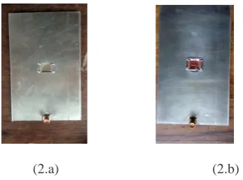
(2.a) (2.b)
Fig.2. (a) Bottom views of a fabricated antenna on a heterogeneous substrate without ground plane. (b) Bottom view of a fabricated antenna on a heterogeneous
[image:3.595.309.544.49.126.2]substrate with ground plane.
Fig. 3. Bottom view of fabricated antenna with slot in a homogeneous substrate.
The proposed circular, triangular and elliptical shape micrpstrip patch antennas are designed at resonance frequency of 2.4 GHz using equations (8), (10) and (11).The proposed designed values of circular, triangular and elliptical microstrip patch antenna are given in table 3.
Table 3: The Designed values of the circular, triangular and elliptical microstrip patch antenna in millimeter.
Antenna Geometry
Parameters Dimensions
Resonance frequency 2.4GHz
Radius of circular patch 17.46
Side length of triangular patch 38.04
Major Radius of elliptical patch 19.02 length of edge feed 17.971
width of edge feed 1.446
length of feed 28.541
width of feed 6.118
The top view of proposed fabricated square, circular, elliptical and triangular patch antenna on a heterogeneous substrate is shown in fig. 4. And fig. 5. Shows test arrangement.
(4.a) (4.b)
(4.c) (4.d)
Fig.4. (a), (b), (c) and (d) Top view of a fabricated square, circular, elliptical and triangular patch antenna
[image:3.595.55.259.59.183.2]respectively on a heterogeneous substrate.
[image:3.595.304.526.188.561.2] [image:3.595.46.220.261.390.2] [image:3.595.111.188.475.609.2] [image:3.595.304.505.592.698.2]III. ANTENNS RESULTS AND DISCUSSION The final optimized proposed heterogeneous substrate multiband antennas are imitated using Ansoft HFSS 13.0 software. The obtained results by simulation software are verified by testing arrangement in terms of return loss and voltage standing wave ratio (VSWR) using scalar network analyzer.
A. RECTANGULAR PATCH ANTENNA ON HETEROGENEOUS SUBSTRATE:
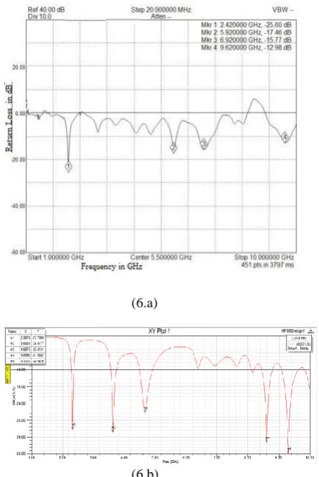
The simulated and fabricated return loss of the proposed rectangular shape patch antenna on a heterogeneous substrate is shown in fig. 6. The theta and phi plane radiation pattern at different resonance frequencies are shown in fig. 7.
(6.a)
(6.b)
Fig. 6. (a) Return loss obtained from fabrication on a
heterogeneous substrate with a rectangle shape patch antenna. (b) Return loss obtained from simulation on a
heterogeneous substrate with a rectangle shape patch antenna
(7.a) (7.b)
(7.c) (7.d)
Fig.7. (a), (b), (c) and (d) are two-dimensional radiation patterns of rectangular patch antenna respectively on a heterogeneous substrate.
B. SQUARE PATCH ANTENNA ON HETEROGENEOUS SUBSTRATE:
The simulated and fabricated return loss of the proposed square shape patch antenna on a heterogeneous substrate is shown in fig. 8. The theta and phi plane radiation pattern at different resonance frequencies is shown in fig. 9.
(8.a)
(8.b)
Fig. 8. (a) Return loss obtained from fabrication on a
heterogeneous substrate with a square shape patch antenna. (b) Return loss obtained from simulation on a
heterogeneous substrate with a square shape patch antenna.
[image:4.595.311.473.48.123.2] [image:4.595.44.271.232.571.2] [image:4.595.304.512.249.543.2]
International Journal of Innovative Technology and Exploring Engineering (IJITEE) ISSN: 2278-3075,Volume-8 Issue-12, October, 2019
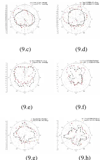
(9.c) (9.d)
(9.e) (9.f)
(9.g) (9.h)
Fig.9. (a), (b), (c), (d), (e), (f), (g) and (h) are two -dimensional radiation patterns of square shape patch
antenna respectively on a heterogeneous substrate. C. CIRCULAR PATCH ANTENNA ON HETEROGENEOUS SUBSTRATE:
The simulated and fabricated return loss of the proposed circular shape patch antenna on a heterogeneous substrate is shown in fig. 10. The theta and phi radiation pattern at different resonance frequencies are shown in fig. 11.
(10.a)
(10.b)
Fig. 10. (a) Return loss obtained from fabrication on a
heterogeneous substrate with a circular shape patch antenna.
(b) Return loss obtained from simulation on a heterogeneous substrate with a circular shape patch antenna.
(11.a) (11.b)
(11.c) (11.d)
(11.e) (11.f)
Fig.11. (a), (b), (c), (d), (e) and (f) are two- dimensional radiation patterns of circular shape patch antenna
respectively on a heterogeneous substrate. D. ELLIPTICAL SHAPE PATCH ANTENNA ON HETEROGENEOUS SUBSTRATE:
The simulated and fabricated return loss of the proposed elliptical shape patch antenna on a heterogeneous substrate is shown in fig. 12. The theta and phi-plane radiation pattern at different resonance frequencies are shown in fig. 13.
[image:5.595.50.214.48.310.2] [image:5.595.308.473.121.396.2] [image:5.595.48.253.454.758.2](12.b)
Fig.12. (a) Return loss obtained from fabrication on a
heterogeneous substrate with an ellipse shape patch antenna.
(b) Return loss obtained from simulation on a heterogeneous substrate with an ellipse shape patch antenna.
(13.a) (13.b)
(13.c) (13.d)
(13.e) (13.f)
Fig.13. (a), (b), (c), (d), (e) and (f) are two -dimensional radiation patterns of ellipse shape patch antenna respectively on a heterogeneous substrate.
E. TRIANGLE SHAPE PATCH ANTENNA ON HETEROGENEOUS SUBSTRATE:
The simulated and fabricated return loss of the proposed triangle shape patch antenna on a heterogeneous substrate is shown in fig. 14. The theta and phi-plane radiation pattern at different resonance frequencies are shown in fig. 15.
(14.a)
(14.b)
Fig.14.(a) Return loss obtained from fabrication on a
heterogeneous substrate with a triangle shape patch antenna.
(b) Return loss obtained from simulation on a heterogeneous substrate with a triangle shape patch antenna.
(15.a) (15.b)
(15.c) (15.d)
(15.e)
Fig.15. (a), (b), (c), (d) and (e) are two -dimensional radiation patterns of triangle shape patch antenna
International Journal of Innovative Technology and Exploring Engineering (IJITEE) ISSN: 2278-3075,Volume-8 Issue-12, October, 2019
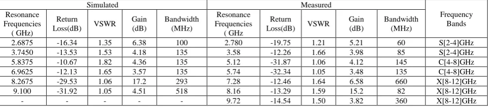
Table 4 to 8 shows the similarities between an imitated and measured results of various parameters like return loss, VSWR, gain, bandwidth and multiband resonance of various shapes of patches like rectangular, square, circular, elliptical and triangular on heterogeneous substrate. It is observed that the simulated and measured results are approximately matched with some variations. The variations are due to small errors occurring during fabrication and testing process. It is cleared that all the proposed antennas on heterogeneous substrate work at four or more than four resonance frequencies and covers S (2-4GHz), C (4-8GHz) and X (8-12GHz) bands applications. A VSWR values less than 2 at all the resonance frequencies indicates good impedance matching and minimum signal loss. The obtained radiation pattern of all the resonance frequencies indicates broadside in nature. The maximum gain and maximum bandwidth are noted for higher frequency bands are in the range of 8 dB to 17.2 dB and 967 MHz, which is required for satellite communication.
Comparing all the simulated and measured results it is seen that square shape patch antenna on heterogeneous substrate has 8 resonance frequencies which cover L (1-2GHz), S (2-4GHz), C (4-8GHz) and X (8-12GHz) bands applications and it is clearly seen that the proposed square shape patch antenna on heterogeneous substrate achieves a good bandwidth and enhanced gain over the others with compact size.
IV. CONCLUSION
The effect of various structures of microstrip patch antennas like rectangular, square, circular, elliptical and triangular on a heterogeneous substrate was studied. It was observed that imitated and measured results of all the proposed antennas have multiband resonance frequencies with enhanced bandwidth and gain. Comparing all the imitated and measured results it is seen that square shape patch antenna on heterogeneous substrate has 8 resonance frequencies which cover L (1-2GHz), S (2-4GHz), C (4-8GHz) and X (8-12GHz) bands. The L band is used by aircraft surveillance i.e. for Low Density Radio Communications Link (LDRCL) application. The S band is used by Communication satellites, Wireless LAN-802.11b and 802.11g, and Bluetooth applications. The C band is used for WLAN and WiMAX applications. The X band is used for radar and satellite communication applications.
REFERENCES
1. C. A. B s “A e T e ry” J W ey 3rdEd Ne Y rk 2005.
2. G. Kumar, and K. P. Ray, “Br db d M cr s r p A e s” B s London, Artech House, 2003.
3. S. Liu, W.Wu, and D.-G. F “S e feed du yer du b d E-shape and U-s p c e f r re ess c mmu c pp c s” IEEEAntennas Wirel. Propag. Lett, Vol. 15, pp. 468-471, 2016. 4. S m C. M. d M. M k yef “A de b d s ed m cr s r p p c
e f r fu ure G” I er J ur f Sc e ce d Engineering (ISSN: 2454-2016), Vol. 2, No. 7, 19-23, 2016.
5. U. Chakraborty, S. Chatterjee, S. K. Chowdhury and P. P. S rk r “A c mp c m cr s r p p c e f r W re ess c mmu c ” Progress in Electromagnetics Research C, Vol. 18, pp.211-220, 2011. 6. D e H .Sc uber D v d M.P z r d A dre Adr “Effec f microstrip antenna substrate thickness and permittivity: comparison of e r es exper me ” IEEE Tr s c s e s andpropagation, Vol. 37, No.6, June 1989.
7. 7. M. K r “T e res freque cy f rec u r m cr s r p e e eme s v r us subs r e ck esses” M cr ve and Optical Technology Letters, Vol. 11, No. 2, pp. 55-59, 1996. 8. R. M s r P. Kuc d A. Kum r “Effec f He f e
Substrate and Width of the Patch on the Performance Characteristics of Microstrip A e ” I er J ur f E ec r c and Computer Engineering (IJECE), Vol. 5, No. 6, pp. 1441-1445, December 2015. 9. C. C. Nj ku W. G. W d J. C. V rd x u “Effec ve permittivity of heterogeneous substrates with cubes in a 3-D L ce” IEEE Antennas Wireless Propag. Lett. Vol. 10, pp. 1480-1483, Feb.2012.
10. P dm v S. T d L Y. S. “Des d S mu f Du B d M cr s r p P c A e He er e e us Subs r e” International Conference on Communication and Signal Processing, April 4-6, 2019.
11. H. F. Shaban, H. A. E m k y d A. A. S “S udy T e Effec s Of Electromagnetic Band-Gap (Ebg) Substrate On Two Patches Microstrip A e ” Pr ress I E ec r m e cs Rese rc B V . 10, 55–74, 2008.
12. Jean-M r e F c H em Rm “Des f mu b d pr ed dipole A e s us p r s c e eme s” M cr ve d p c technology letters, Vol. 48, Issue 8, pp. 1639 – 1645, May 2006. 13. M. Samsuzzaman, M. T. Islam, J. S. Mandeep, and N. Misran,
“Pr ed Wide-Slot Antenna Design with Bandwidth and Gain Enhancement on Low-C s Subs r e” Sc e f c W r d J ur V . 2014.
14. X. Sun, G. Zeng, H.-C. Yang, Y. Li, X.-J. L d L. W “Des of an edge-fed quad-band slot antenna for GPS/ WIMAX/WLAN pp c s” Progress in Electromagnetics Research Letters, vol. 28, pp. 111–120, 2012.
15. Abhishek K. Saroj, Mohd. G. Siddiqui, Mukesh Kumar, and Jamshed A. A s r “Des f Mu b d Qu d-Rectangular Shaped Microstrip A e f r W re ess App c s” Pr ress I E ec r m e cs Research M, Vol. 59, 213–221, 2017.
16. Francisco Carlos Gurgel da Silva Segundo, Antonio Luiz Pereira de S que r C mp s A fred G mes Ne “A Des Pr p s F r U r de B d Freque cy Se ec ve Surf ce” J ur f M cr ves Optoelectronics and Electromagnetic Applications, Vol. 12, No. 2, December 2013
17. Te-Kao Wu, and Shung-Wu Lee “Mu b d Freque cy Se ec ve Surface Mu r P c E eme s” IEEE Tr s c s Antennas and Propagation, Vol. 42, No. 11, pp. 1484–1490, 1994. 18. John Papapolymerou, Rhonda F. Drayton, and Linda P.B. Katehi,
“Surf ce W ve M de reduc F r Rec u r M cr s r p e s On high-Index M er s” D rec s f r e Nex Ge er f MMIC Devices and Systems pp 153-160, 1997.
19. 19. I.J. J mes d P.S. H “H db k f M cr s r p A e s” Vol.1, Peter Peregrinus Ltd, 1989.
20. S. C kr b r y U. C kr b r y S. G s M. C kr b r y “Des anddevelopment of multiband circular microstrip antenna with res s e r u d p e” I . J. Adv. Res. Electron.Commun. Eng. (IJARECE) 5(3), 537–542, 2016.
21. M es C. P d P. M. H d “Pr x m y C up ed Equ er Triangular Microstrip Antenna with Diamond Shape Slot for Dual B d Oper ” I er J ur f Adv ced Rese rc Electrical, Electronics and Instrumentation Engineering, Vol. 3, Issue 11, November 2014.
Table 4: Similarities between an experimental and imitated result of rectangular shape microstrip patch antenna with a heterogeneous substrate.
Simulated Measured
Frequency Bands Resonance frequencies (GHz) Return
loss(dB) VSWR Gain (dB) Bandwidth (MHz) Resonance frequencies ( GHz) Return
loss(dB) VSWR Gain (dB)
Bandwidth (MHz)
2.3275 -27.76 1.21 5.00 90 2.420 -25.60 1.13 4.88 80 S[2-4] GHz
3.6325 -28.61 1.13 4.13 180 - - - S[2-4] GHz
4.6675 -22.81 1.15 4.76 405 5.920 -17.46 1.31 3.92 130 C[4-8] GHz
8.6050 -31.58 1.82 14.1
8 337.5 6.920 -15.77 1.39 5.12 450 C[4-8] GHz
[image:8.595.51.552.72.176.2]9.3025 -34.92 1.39 3.90 517.5 9.620 -12.98 1.61 4.67 320 X[8-12] GHz
Table 5: Similarities between an experimental and imitated result of square shape microstrip patch antenna with a heterogeneous substrate.
Simulated Measured
Frequency Bands Resonance Frequencies ( GHz) Return
Loss(dB) VSWR Gain (dB) Bandwidth (MHz) Resonance Frequencies ( GHz) Return
Loss(dB) VSWR Gain (dB)
Bandwidth (MHz)
1.81 -13.43 1.54 8.08 45 1.9 -13.95 1.49 7.98 60 L[1-2]GHz
3.475 -13.63 1.52 5.09 105 3.6 -23.38 1.14 5.29 120 S[2-4]GHz
3.97 -22.54 1.16 1.81 112.5 4.12 -23.54 1.14 2.08 100 S[2-4]GHz
5.2525 -10.81 1.80 2.68 112.5 5.10 -30.65 1.06 3.77 140 C[4-8]GHz
6.67 -28.49 1.07 2.74 225 5.38 -17.12 1.32 2.86 200 C[4-8]GHz
7.27 -13.00 1.57 5.50 292.5 6.84 -19.20 1.24 5.87
967 C[4-8]GHz
8.11 -15.27 1.41 9.28 200 7.40 -26.67 1.09 8.98 C[4-8]GHz
[image:8.595.41.541.206.327.2]9.73 -11.68 1.70 10.6 450 9.58 -15.59 1.41 9.23 325 X[8-12]GHz
Table 6: Similarities between an experimental and imitated result of circular shape microstrip patch antenna with a heterogeneous substrate.
Simulated Measured
Frequency Bands Resonance Frequencies ( GHz) Return
Loss(dB) VSWR Gain (dB) Bandwidth (MHz) Resonance Frequencies ( GHz) Return
Loss(dB) VSWR Gain (dB)
Bandwidth (MHz)
2.35 -12.70 1.59 6.38 60 2.44 -15.17 1.43 5.02 80 S[2-4]GHz
3.8125 -15.74 1.38 3.30 135 3.74 -12.91 1.59 4.01 100 S[2-4]GHz
5.77 -12.19 1.65 3.09 225 4.08 -23.33 1.15 3.89 242 C[4-8]GHz
6.9625 -27.03 1.09 7.02 293 6.96 -40.31 1.03 6.38
680 C[4-8]GHz
8.29 -12.09 1.66 7.99 145 7.28 -17.08 1.32 8.03 X[8-12]GHz
9.8875 -23.99 1.13 2.60 787 9.42 -13.42 1`.52 3.45 400 X[8-12]GHz
Table 7: Similarities between an experimental and imitated result of elliptical shape microstrip patch antenna with a heterogeneous substrate.
Simulated Measured
Frequency Bands Resonance Frequencies ( GHz) Return
Loss(dB) VSWR Gain (dB) Bandwidth (MHz) Resonance Frequencies ( GHz Return
Loss(dB) VSWR
Gain (dB)
Bandwidth (MHz)
2.6875 -16.34 1.35 6.38 100 2.780 -19.75 1.21 5.21 60 S[2-4]GHz
3.7450 -13.53 1.53 4.18 135 3.58 -12.26 1.66 3.98 85 S[2-4]GHz
5.8375 -10.67 1.82 4.36 135 5.12 -31.87 1.06 4.12 145 C[4-8]GHz
6.9625 -12.13 1.65 3.57 135 5.74 -32.34 1.05 3.48 135 C[4-8]GHz
8.2675 -29.53 1.06 17.2 293 7.28 -12.46 1.64 6.58 660 X[8-12]GHz
9.100 -31.92 1.05 4.51 518 8.16 -13.29 1.59 15.2 82 X[8-12]GHz
- - - 9.72 -14.54 1.50 3.82 360 X[8-12]GHz
Table 8: Similarities between an experimental and imitated result of triangular shape microstrip patch antenna with a heterogeneous substrate.
Simulated Measured
Frequency Bands Resonance Frequencies ( GHz) Return
Loss(dB) VSWR Gain (dB) Bandwidth (MHz) Resonance Frequencies ( GHz) Return
Loss(dB) VSWR Gain (dB)
Bandwidth (MHz)
2.4625 -15.67 1.39 2.84 57.5 2.46 -19.34 1.24 3.01 60 S[2-4]GHz
4.3525 -18.65 1.26 2.95 180 4.2 -10.10 1.90 3.45 25 C[4-8]GHz
- - - 6.92 -15.27 1.41 5.98
660 C[4-8]GHz
7.350 -10.43 1.86 6.44 157.5 7.30 -13.78 1.51 6.28 C[4-8]GHz
8.450 -10.92 1.79 7.70 157.5 8.24 -10.09 1.92 7.02 20 X[8-12]GHz
[image:8.595.54.544.362.463.2] [image:8.595.48.550.496.606.2]International Journal of Innovative Technology and Exploring Engineering (IJITEE) ISSN: 2278-3075,Volume-8 Issue-12, October, 2019
AUTHORS PROFILE
S. T. Padmavati working as Assistant Professor in Department of Electronics and Communication in Appa Institute of Engineering and Technology, Gulbarga, Karnataka , India .