International Journal of Innovative Technology and Exploring Engineering (IJITEE) ISSN: 2278-3075, Volume-8 Issue-10, August 2019
L-Shaped Monopole Antenna with Modified Partial
Ground Plane for Multiband Operation
Prachi Pandey, Neelesh Agrawal, Mukesh Kumar, Navendu Nitin, Anil Kumar
Abstract- In this paper a design of L-shaped monopole antenna (LMA) with modified partial ground plane for multiband operation is presented. The `dimension of proposed antenna is 40× 47 mm2 with 1.6 height using Teflon substrate having dielectric constant 2.1. The ground plane is amended by inserting an anti-symmetric horizontal L-slots. Single band to multiband behaviour is accomplished by applying two horizontal L-slots on partial ground plane of LMA. Both the slots are antisymmetric to Y-axis. The parametric study has also been done which is responsible for antenna behaviour. The operating frequency bands of designed antenna are 2.35-2.91GHz,3.24-3.51GHz ,4.31-5.30GHz and 5.90-6.31GHz which is suitable for Bluetooth (2.4GHZ),WLAN (2.4GHz,5.2GHz), WiMAX (2.3GHz, 2.5GHz, 3.5GHz, 5.2GHz), C-band (4-8GHz) and S-DMB (2.6GHz) applications. By using the HFSS simulator we accomplished that our designed antenna show an enhancement of bandwidth and good matching impedance.
Keywords: LMA, PARTIAL GROUND PLANE, MULTIBAND, L-SLOTS, WLAN, Wi-MAX.
I. INTRODUCTION
Nowadays, antenna develops rapidly, as an significant part of wireless devices. Recently monopole microstrip antennas are important due to its applications and characters namely low profile, small volume, light weight and easy fabrication, attractive for several wireless systems namely Bluetooth, satellite digital multimedia broadcast (SDMB), worldwide Interoperability for Microwave Access (WiMAX) and wireless local area network (WLAN) systems. Different kinds of designs, shapes and techniques has been presented to achieve dual band and multiband operation such as an inverted-F strip, inverted-F adds inverted-L structure [1-2]. In [1] dual-band operation in the 2.4 GHz (2.4-2.484 GHz) and 5.2 GHz (5.15-5.35 GHz) is achieved by integrating F-shaped monopole antenna using microwave substrate with a three metal lines having same width. In [2] combining inverted-F and inverted-L widen the bandwidth of the resonant frequency of the antenna. Bandwidth is enhanced by the insertion of the inverted-L-shaped coupled strip with C-shaped radiating patch [3].
Revised Manuscript Received on August 03, 2019.
Prachi Pandey, M. tech Scholar, ECE Department, SHUATS, Prayagraj India.
Neelesh Agrawal, Assistant Professor, ECE Department SHUATS, Prayagraj, India.
Mukesh Kumar, Assistant Professor, ECE Department SHUATS, Prayagraj, India.
Navendu Nitin, Assistant Professor, ECE Department SHUATS, Prayagraj, India.
Anil Kumar, Head Of Department, ECE Department SHUATS,
II. DESIGN PROCEDURE
A. Antenna Design And Configuration
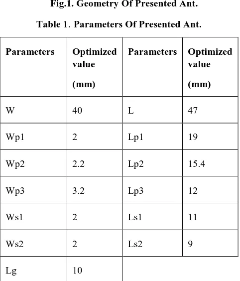
The model of designed LMA with DGS is presented in Fig.1. Presented antenna is fed by 50Ω offset microstrip feedline at the Teflon dielectric. Teflon dielectric is used with εr=2.6 and height is 1.6mm. Width of microstrip feedline is about 3.2mm. The dimension of presented antenna is taken into consideration from [17]. Geometric specifications of the presented antenna are listed in Table1.
[image:2.595.323.539.47.343.2]Fig.1. Geometry Of Presented Ant. Table 1. Parameters Of Presented Ant.
Parameters Optimized value (mm)
Parameters Optimized value (mm)
W 40 L 47
Wp1 2 Lp1 19
Wp2 2.2 Lp2 15.4
Wp3 3.2 Lp3 12
Ws1 2 Ls1 11
Ws2 2 Ls2 9
Lg 10
B. Progression Of Proposed Design
Fig.2 represent the evolution of presented antenna. Antenna1 consist of a L-shaped patch on Teflon substrate, fed with microstrip line is demonstrated in Fig 2(a.). In Fig 2(b.) Antenna2 shows the presented antenna in which the ground plane is modified by cutting an antisymmetric L-shaped slots.
Fig2 (a.)L-Shaped Monopole Ant. (b.) Proposed Ant. Fig.3 represents the performance analysis of Antenna 1 and Antenna2. The absence of slot in Antenna 1 achieves single band operation therefore, to improve its performance from single band to multiband operation an anti-symmetric horizontal L-slot has been defected in the ground presented in Antenna 2. The slots inserted in the ground plane will modify the current pattern.
Fig 3. Simulated S11 Of Antenna 1 And Antenna 2 III. PARAMETRIC STUDIES
On the basis of the design there are some parameters which is responsible for multiband operation and have significant consequences on the antenna performance, will be purporting in this paper.
(a.) Antenna 1
(b.) Antenna 2
(i.)
(ii.)
[image:2.595.69.267.182.345.2] [image:2.595.49.290.353.635.2] [image:2.595.326.527.467.651.2]International Journal of Innovative Technology and Exploring Engineering (IJITEE) ISSN: 2278-3075, Volume-8 Issue-10, August 2019
A. Effect Of Ground Length (Lg)
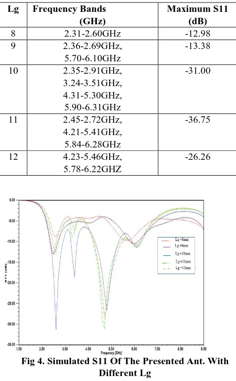
[image:3.595.354.505.55.413.2]The consequences on the characteristic of designed antenna by varying ground length (Lg) is shown in fig.4. The consequence of ground size was more notable in the y-direction caused by the verity that the radiating edges of a microstrip patch antenna are in the x-direction. The value of Lg is varied from 8mm to 12mm with step size 1mm. Antenna covers multiband at both10mm and 11m but antenna covers more frequency ranges at Lg=10mm. For multiband operation Lg is set to be at 10mm.
Table.2 Effect of Lg On Proposed Antenna Lg Frequency Bands
(GHz)
Maximum S11 (dB)
8 2.31-2.60GHz -12.98
9 2.36-2.69GHz, 5.70-6.10GHz
-13.38
10 2.35-2.91GHz, 3.24-3.51GHz, 4.31-5.30GHz, 5.90-6.31GHz
-31.00
11 2.45-2.72GHz, 4.21-5.41GHz, 5.84-6.28GHz
-36.75
12 4.23-5.46GHz, 5.78-6.22GHZ
-26.26
[image:3.595.351.502.61.207.2]
Fig 4. Simulated S11 Of The Presented Ant. With Different Lg
B. Effect Of Variation Of Shape Of Slots
Fig.5(a.) and (b.) presents the vertical and the horizontal slots defected on the ground of LMA respectively.
Fig 5. (a.) Horizontal Slot LMA
(b.) Vertical Slot LMA
Fig 5. (a.) Horizontal Slot LMA (b.) Vertical Slot LMA Fig.6(a.) and 6(b.) presents the S11 of horizontal slot LMA and vertical slot LMA. Insertion of the Vertical slot will only cover frequency band from 4.59 to 5.95 GHz while the horizontal slot achieves multiband from 2.47 to 6.04 GHz. The disadvantage of both the antenna is that it doesn’t cover 2.4GHz wireless applications. In the designed antenna the antisymmetric L-slot is defected on the ground which achieves multiband including 2.4GHz wireless applications and improved bandwidth.
[image:3.595.42.281.203.588.2] [image:3.595.328.529.560.716.2](b.)
Fig 6. (a.) S11 of Vertical Slot LMA (b.) S11 of Horizontal Slot LMA
IV. RESULT AND DISCUSSIONS
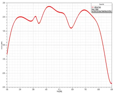
[image:4.595.73.267.50.214.2]LMA with anti-symmetric horizontal L-slots on ground plane is proposed and simulated using HFSS software. In this we will discuss the result of designed antenna in terms of S11, VSWR, gain and radiation pattern as a function of frequency. Simulate return loss of the present antenna is depicted in Fig.7. From simulated result it is concluded that the designed antenna achieves multiband frequencies at 2.34-2.91GHz, 3.24-3.51GHz ,4.28-5.31GH and 5.90-6.31 with fractional bandwidth(S11 ) 21.292%,7.94, %,21.45%and6.72% respectively. The designed antenna achieves resonant frequencies at 2.6GHz,3.4GHz, 4.8GHz and 6.1GHz. The antenna is designed at some selected resonating frequency which leads to some bandwidth, then the insertion of slot overlays the fundamental mode of antenna and generates higher order mode which overlays the original bandwidth which gradually increases the overall bandwidth of the antenna.
[image:4.595.323.532.50.200.2]Fig 7. Simulated S11 Of The Designed Ant. Fig.8 presents the VSWR of the presented antenna. For all resonant frequencies the VSWR ≤ 2 which indicates that the designed antenna has good impedance matching.
Fig 8. Simulated VSWR Of The Designed Ant. Simulated gain of designed antenna is manifested in Fig9. From Fig.9 it is perceived that the gain acquired in the operating band is 3.12dB at 4.28GHz. Due to insertion of slot the electrical length of ground enhances. The strong coupling b/w ground and patch cause enhancement in gain. The presented antenna obtains positive gain at all the resonating frequencies which indicate efficient performance of the designed antenna.
[image:4.595.333.519.353.505.2] [image:4.595.63.274.502.665.2]International Journal of Innovative Technology and Exploring Engineering (IJITEE) ISSN: 2278-3075, Volume-8 Issue-10, August 2019
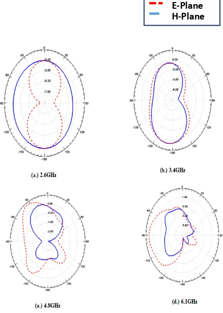
Fig 10. Radiation Patterns Of Designed Ant. At Resonating Frequencies
[image:5.595.59.277.462.617.2](a.) 2.6GHZ, (b.)3.4GHZ, (C.)4.8GHZ, (d.)6.1GHz Table3. presents the overall result of designed antenna presenting the important parameters of the antenna.
Table 3. Result Of Designed Ant.
Parameters Value
Impedance Bandwidth 2.34-6.31 GHz
Return Loss -31dB
Resonant Frequency 2.6,3.4,4.8 and 6.1 GHz
Gain 3.12dB
VSWR ≤ 2
Table 4. presents the comparison of impedance bandwidth and size of designed antennas with reference papers.
TABLE 4. Comparison Of The Dimensions And Performance Of The Designed Ant. With Other Ants. Anten
na
Method Size Impedance
Bandwidth (GHz) Ref.[2] Using
inverted-F adds inverted-L
350mmx16 0mm
110MHz and 325MHz
Ref.[4] Two asymmetric horizontal strips.
40mmx50 mm
0.93 GHz at the frequency band of 2.4 GHz, and 1.41 GHz at the frequency band of 5 GHz.
Ref.[12 ]
A trapezoid patch and a quasi-fractal slot
structure.
110mmx11 0mm
1.74–2.38 and 4.46–5.56 GHz
Propos ed
LMA with
anti-symmetric horizontal L-slots.
40x47 2.35-2.91GHz, 3.24-3.52GHz, 4.30-5.30GHz, 5.90-6.31GHz
V. CONCLUSION
The electrically small LMA is introduced for modern wireless communication system. The presented antenna is designed by inserting an anti-symmetric horizontal L-slots in L-shaped monopole antenna to improve its performance from single band to multiband operation. Its simulated -10dB impedance bandwidths are 560MHz (2.35-2.91GHz),280MHz (3.24-3.52GHz),990MHz(4.31-5.30GHz), 410MHz(5.90-6.31GHz) and hence achieve the resonating frequencies at 2.6GHz,3.4GHz ,4.8GHz and 6.1GHz.The simulated result presents the designed antenna which shows the good impedance matching ,efficient performance over an bandwidth of 2.35-6.31GHz which operate for Bluetooth (2.4GHZ),WLAN (2.4GHz,5.2GHz), WiMAX (2.3GHz, 2.5GHz, 3.5GHz, 5.2GHz) , C-band (4-8GHz)and S-DMB (2.6GHz) applications.
REFERENCES
1. H.D. Chen, J.S. Chen and Y.T. Cheng” Modified inverted-L monopole
antenna for 2.4/5GHz dual-band operations” Electronics Letters, Vol. 39, No. 22, October 2003.
2. Z.H. Li, T.M. Xiang, SONG S. Xian” Study On Dual-Frequency Planar Monopole Antennas” IEEE International Symposium on Microwave, Antenna, Propagation and EMC Technologies for Wireless Communications Proceedings,2005
3. G.H. Kim and T.Y. Yun “Compact UWB Monopole Antenna With an
Inverted-L-Shaped Coupled Strip” IEEE Antennas And Wireless Propagation Letters, Vol.12 ,2013.
4. N. Chang and J.H. Jiang” Meandered T-Shaped Monopole Antenna” IEEE Transactions On Antennas And Propagation, Vol. 57, No. 12, December 2009.
5. S.B. Chen, Y.C. Jiao, W. Wang, and F.S. Zhang”Modified T-Shaped
Planar Monopole Antennas for Multiband Operation” IEEE
Transactions On Microwave Theory And Techniques, Vol. 54, No. 8, August 2006.
6. C.Y. Huang and P.Y. Chiu” Dual-Band Monopole Antenna With
Shorted Parasitic Element” Electronics Letters Vol. 41 No. 21, 13th October 2005.
7. H. Wang “Dual-resonance monopole antenna with tuning stubs” IEE
Proc.-Microw. Antennas Propag., Vol. 153, No. 4, August 2006.
8. X.R., Steven Gao and Y.Z Yin “Compact Tri-Band Monopole
Antenna With Hybrid Strips For Wlan/Wimax Applications” Microwave And Optical Technology Letters / Vol. 57, No. 1, January 2015.
9. Y.S. Li and W.H. Yu “A Miniaturized Triple Band Monopole Antenna for WLAN and WiMAX Applications” Hindawi Publishing Corporation International Journal of Antennas and Propagation Volume 2015, Article ID 146780, 5 pages,2015.
10. P.M. Paul, K. Moorthy K.M. S. Sharawi “A Tri-Band Slot Antenna Loaded With Split Ring Resonators” Microw Opt Technol Lett. 2017.
11. S.M.A. Nezhad and H.R. Hassani “A Novel Triband E-Shaped Printed
Monopole Antenna for MIMO Application” IEEE Antennas And Wireless Propagation Letters, Vol. 9, 2010.
12. T. Hong, S.X. Gong, Ying Liu and W. Jiang, “Monopole Antenna With Quasi-Fractal Slotted Ground Plane for Dual-Band Applications” IEEE Antennas And Wireless Propagation Letters, Vol. 9, 2010. 13. C.H. Huang and E.Z. Yu “A Slot-Monopole Antenna for Dual-Band
WLAN Applications “IEEE Antennas And Wireless Propagation Letters, Vol. 10, 2011.
14. H. U. Iddi, M.R. Kamarudin, T.A. Rahman and R. Dewan “Design of
Dual-Band B-shaped Monopole Antenna for MIMO Application” IEEE 2012.
15. A.Kumar1 and P.V.Naidu” A Novel Compact Printed ACS Fed
Dual-band Antenna for Bluetooth/WLAN/WiMAX Applications” Progress In Electromagnetic Research Symposium (PIERS),2016.
16. M.Kumar, R. Saxena, J. A. Ansari, A .Singh, M. G. Siddiqui, A. K. Saroj, G. P. Singh “Analysis of Half Circular F Slot Multiband Microstrip Antenna with Defected Ground Structure” Recent Advances on Engineering, Technology and Computational Sciences (RAETCS) ,2018.
17. M.T. Tan and B.Z. Wang “A Dual-Band Circularly Polarized Planar Monopole Antenna For WLAN/Wi-Fi Applications” National Natural Science Foundation Of China and the Specialized Research Fund for the Doctoral Program of Higher Education of China,2015.
AUTHORS PROFILE
Prachi Pandey received B. Tech degree in ECE in 2016 from B.B.S. College of Engg. & Technology.
Pursuing M. Tech degree in wireless
Communication Engg. from SHUATS, Prayagraj (Allahabad), U.P, India. One publication in UGC approved journal. Member at IEEE Organization. Her research area is in Microstrip Patch antenna. Neelesh Agrawal received B.Tech degree in ECE in 2006 & M.Tech degree in Advance Communication System Engg in 2009 from SHUATS (Formly known as A.A.I-DU),Prayagraj, U.P, India. He is working as an Assistant Professor in SHUATS, Prayagraj.
Mukesh Kumar received B.Tech degree in ECE in 2007 & M.Tech degree in Advance Communication System Engg. in 2010 from SHUATS (Formly known as A.A.I-DU), Allahabad, U.P, India. He is Currently Pursuing P.hD from J.K.Institute of Applied Physics and Technology, Allahabad University, U.P., India. His research area is in Microstrip Patch antenna.
Navendu Nitin received B.Tech degree in ECE in 2007 & M.Tech degree in Advance Communication System Engg in 2009 from SHUATS (Formly known as A.A.I-DU),Prayagraj, U.P, India. She is working as an Assistant Professor in SHUATS Prayagraj.
Dr. Anil Kumar is Assistant Professor in ECE Department at SHUATS Prayagraj (Allahabad). He obtained B.E from MMMEC Gorakhpur in ECE, M.Tech. from IIT BHU Formerly IT B.H.U. Varanasi in Microelectronics Engg. And he has done Ph.D. from SHIATS-DU Allahabad. He guided various projects & research at undergraduate & postgraduate level. He published many research papers in different journals. He has more than 14 years teaching experience and actively involved in research and publications. His area of interest includes Antenna, microwave, artificial neural network and VLSI.