International Journal of Innovative Technology and Exploring Engineering (IJITEE) ISSN: 2278-3075, Volume-8 Issue-5S March, 2019
Abstract: Induction motor is predominently used as driver for industrial and commertial applications.Although induction motor has many significance it offers poor efficiency when the applied load on a motor is low. This factor limits the application of induction motor for lighter torque conditions. So its become mandatory enhance the efficiency of motor when the applied load is lesser. It is possibleto improve the performance of a motor by means of mathematical modelling. In this the first principle model of an motor is developed. The efficiency of a motor for various load condition is calculated from the data obtained from mathematical model by considering all the losses associated with motor. The performance of model is evaluated for different control algorithms like fuzzy logic and Particle swarm optimization.
Keywords: Induction Motor, Mathematical Model, Fuzzy logic, Particle swarm optimization.
I. INTRODUCTION
The energy utilization of Induction motor is more than half of world total power production. In high capacity machines even small percentage loss leads to considerable economical loss to a consumer. A tiny improvement in reducing the losses associated with motor can reduce the wastage of power significantly. Hence, it becomes important to optimize the power utilized by motor in lighter load condition in order to improve its efficiency. The three phase induction motor, especially squirrel cage induction motor is commonly used for industrial applications and to operate at all load conditions from lighter load to full load conditions. The control of induction motor is quite complex compare to control of DC drives. The selection of suitable control technique for controlling AC drives is appreciated. Vector based control provides better transient response than scalar control. Space vector control became the industrial standard control for AC drives in order to control the speed and torque[1].
The main objective is to develop an arbitrary reference frame based mathematical model of a drive for estimate the efficiency for various load condition, especially for low load condition. It is necessary to deeply analyze the efficiency of induction motor for various points of operating region.
Revised Manuscript Received on March 08, 2019.
J.Arulvadivu, Assistant Professor, Department of Electronics and Instrumentation Engineering, Karpagam College of Engineering, Coimbatore, India
P.Palpandian, Assistant Professor, Department of Electronics and Instrumentation Engineering, Karpagam College of Engineering, Coimbatore, India
S.Manoharan, Professor and Head, Department of Electronics and Instrumentation Engineering, Karpagam College of Engineering, Coimbatore, India
From the analysis, it conclude that efficiency is poor over certain point of operating region. Generally motor operates with poor efficiency at the region of low load. It is not possible to operate the drive at low load conditions in all applications, some applications like traction, electric vehicle etc are need to be operated in various load condition. So it become mandatory to maintain the efficiency of drive in all load condition. In this work efficiency model of induction motor is developed by including all the losses associated with drives[2].
II. MODELLING OF ELECTRICAL DRIVE
Space vector modelled induction motor operates similar to separately excited dc motor. In separately excited DC motor flux and torque independent parameters which can be controlled without affecting each other due to its natural decoupling between the field flux control current and torque control current. Construction wise field windings and armature windings are placed in the direction of orthogonal to each other but it is not there in ac drives, so an interaction between the stator current and rotor torque is present in AC drives[3].
In space vector model the torque component ( Iqs ) and
speed component (Ids )are decoupled. When both
components are decoupled, the variation in torque control component(Iqs) does not affect the flux component(Ids)
likewise variation in flux control component(Ids) will not
affect the torque component(Ids). This will helps to improve
the transient response of Induction motor[4].
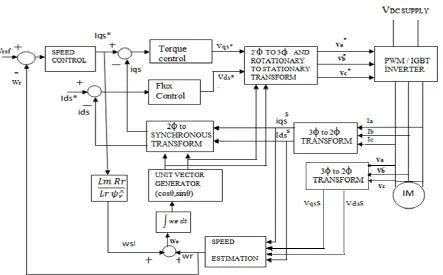
To study the behaviour of vector control, the dynamic model of the induction motor has to be developed. So an arbitrary reference frame is used for induction motor modelling. Space vector PWM is special technique used for controlling the switching sequence of power transistor in voltage source inverter. Space vector PWM is providing better efficiency compared to other PWM techniques it also generates less harmonics. Thus space vector PWM inverter is modelled using Matlab Simulink and analyzed the performance of drive for low load condition. model of drive can be developed by using differential equations, there are six mathematical equations which is associated with stator reference frame for developing induction motor model[5], are as follows
s ds r dr r s m qr r s r m sr r s s r r m ds aL V L aL PL L aL R L i L aL R L R L dt di 2 2 2 2 2 (1)
s qs r qr r s m dr r s r m ds r s s r r m qs aL V L aL PL L aL R L i L aL R L R L dt di 2 2 2 2 2 (2)Efficiency Enhancement of Induction Motor
Using Soft Computing Technique
r qr dr r r ds r r m dr P L R i L R L dt
d
2
(3)
r dr qr r r qs r r m qr
P
L
R
i
L
R
L
dt
d
2
(4)
J
B
J
T
i
i
J
L
PL
dt
d
l rds qr qs dr r m
r
4
3
(5)
dr qs qr ds
r m
e
i
i
L
PL
dt
dT
4
3
(6) Where
i
ds- stator d-axis current,i
qs-stator q-axis current,dr
- Rotor d-axis flux Linkage,
qr- Rotor q-axis fluxLinkage,
r- Rotor speed,T
e- Developed Torque,L
m-Magnetizing inductance,
L
s- Stator Inductance,a
- constant,R
r- Rotor resistance,B
- Friction coefficient,P
- No of poles, J - Moment of InertiaDue to continuous variation in mutual inductance between stator and rotor winding its quite difficult to form a voltage equation of induction motor. This problem can be eliminated by changing the variables to another reference frame. Even though parameters can be extended to any reference frame of machine, Theoretically. The widely used reference frames are synchronously rotating reference frame and stationary reference frame.. Clarke and Park transformations can be used to transform the equations to these reference frames. The respective voltage and torque equation can be used to model the induction motor.
The voltage equations with respect to arbitrary reference frame could be achieved by assuming the speed of machine to ω. That is ω =0 for standstill,
ω = ωr or the rotor, and ω = ωe for the synchronously
rotating reference frame.
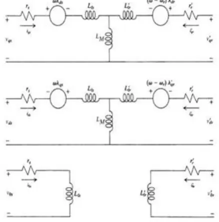
[image:2.595.316.536.163.386.2]The induction motor is considered as a 3-phase RL circuit. The voltage equations in an arbitrary reference frame can be written as follows,
[image:2.595.54.519.443.683.2]Fig. 1 Equivalent circuit of Induction motor in arbitrary reference frame
Fig. 2 Overall Simulink Model of Induction Motor
Motor Parameters
HP = 3,V = 230v, N = 1435rpm,Tm = 11.8Nm, IL =
5.75A, Rs= 0.445ΩŸ, Xls = Xlr = 0.763Ω, Xm = 26.23ΩŸ,
International Journal of Innovative Technology and Exploring Engineering (IJITEE) ISSN: 2278-3075, Volume-8 Issue-5S March, 2019
Fig. 3 Speed of Induction motor
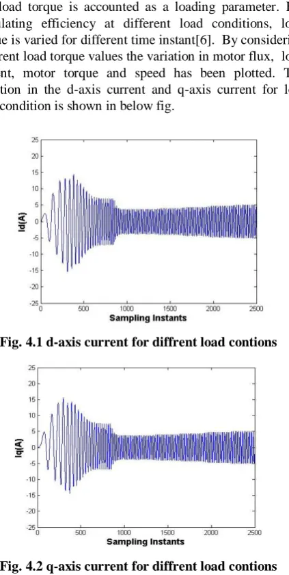
From the figure1, 780 sampling instants are taken to reach rated speed of the motor. If full voltage is applied to the motor at the time of starting then initial current of a motor will be dangerously higher which may cause over heating of coils of a motor. So in order to minimize the starting current of IM drive Variable voltage/ frequency control is applied for minimize initial current. Reduction in the ratio between V/F will lead to increase response time of the induction motor which will affect the transient response of motor. In this load torque is accounted as a loading parameter. For calculating efficiency at different load conditions, load torque is varied for different time instant[6]. By considering different load torque values the variation in motor flux, load current, motor torque and speed has been plotted. The variation in the d-axis current and q-axis current for low load condition is shown in below fig.
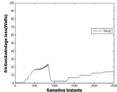
[image:3.595.335.514.160.471.2]Fig. 4.1 d-axis current for diffrent load contions
Fig. 4.2 q-axis current for diffrent load contions
The flux linkage between stator and rotor does not varies with respect to change in load. At the time of stating the
flux linkage will be low due to low ratio of V/F. The speed of motor is reducing with increase in load. The variation in speed of motor is shown in fig. 3. Since applied load is low, the variation in the speed of the motor will be less.
[image:3.595.67.279.331.751.2]The torque developed by motor is shown in fig.5. whereas the mechanical power produced by induction motor can be calculated from the value of speed and torque developed by motor which is shown in fig. 6
[image:3.595.77.265.437.619.2]Fig. 5 Torque developed by motor
Fig. 6 Output power of the motor
III. DETERMINATION OF LOSSES
Total Loss = Pc+ Pcus+ Pcur +Pfw +Ps
Core loss
It's a constant loss which does not change with change in load. Core loss is the dominating loss at lower load condition which contributes major part of total loss. This loss is voltage dependent and this can be minimized by reducing the supply voltage of the drive.
Eddy current loss
This loss occurs due to circulating current in a machine and it is frequency and flux density dependent. this loss converted in the form of heat.
Pe αf2B2
f =operating frequency, B =Maximum flux density.
Hysteresis loss
Hysteresis loss is due to the magnetic reversal of magnetic field.
[image:3.595.73.266.567.729.2]It can be minimized by optimizing supply frequency and maximum flux density. The core loss takes place in R0 due
to flow of core loss current Iw. The no load current flowing
in a machine winding will be the combination of Iw+Iμ.
When we reduce core loss current by controlling the supply voltage core loss can be reduced.
Nominal values of thickness of lamination can be 0.3mm to 0.5 mm depending upon rating of motor.
[image:4.595.335.517.52.185.2]Nominal values of Flux density can be between 0.3 wb/m2 to 0.45wb/m2
Fig. 7 Eddy current loss
Fig. 8 Hysteresis loss Stator and rotor copper loss
Stator copper loss varies as the function of stator current of the motor. stator copper loss can be calculated easily by measuring stator current.
Pcus=Is2*Rs
Rotor copper loss can be calculated by means of rotor current measurement but it cannot be done directly. The rotor current can be calculated by knowing turns ratio between stator and rotor windings.
Pcur=Ir2*Rr
Total copper loss
Pcu= 3*(Is2 Rs+Ir2 Rr)
Is− stator current.
Rs− stator resistance.
Ir − rotor current.
Rs – rotor resistance.
Stator copper loss and rotor copper loss is shown in the fig 9 and fig 10 respectively for variations in the load.
[image:4.595.77.264.186.550.2]Fig. 9 Stator copper loss for various load condition
Fig. 10 Rotor copper loss for various load condition Mechanical losses
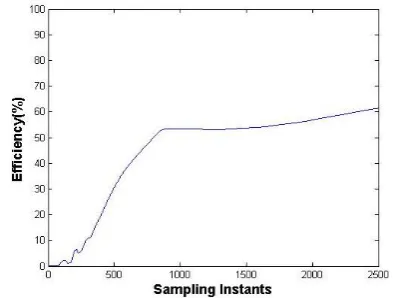
[image:4.595.332.522.211.354.2]The main cause for mechanical losses are friction between stator and rotor coupling and opposition of wind to the rotation of the motor. As per IEEE standard, friction loss will be 1% of total output power up to 5HP motor. The standard value varies as the function of motor rating. Friction and windage loss is shown in the Fig.11.
Fig. 11 Friction and windage loss for various load condition
Stray Loss
Stray loss is the combination of pulsation loss, Surface loss, Cross−path loss, Flux leakage loss and Harmonic current loss of rotor part. Out of this pulsation loss and harmonic current loss occupies 50% of total stray loss. The stray loss can be calculated using below formula.
[image:4.595.332.521.477.625.2]International Journal of Innovative Technology and Exploring Engineering (IJITEE) ISSN: 2278-3075, Volume-8 Issue-5S March, 2019
[image:5.595.80.264.82.216.2]Since stray loss is depending on stator current, it varies as the function of load.
Fig. 12 Stray loss for various load condition
Figure 13 shows the total loss for different load condition.
Fig. 13 Total loss for various load condition
[image:5.595.326.523.225.374.2]Input power is combination of output power and total losses. Following Fig14 shows the Input power to the motor for variation in load between 0 to 50%.
Fig. 14 Input power for various load condition
IV. EFFICIENCY CALCULATION
Efficiency is the ratio between output power and input power. In this input power is unknown quantity and it is calculated from output power and total losses. Efficiency can be calculated by,
LOSSES
R
OUTPUTPOWE
POWER
OUTPUT
EFFICIENCY
Efficiency varies as the function load. Efficiency of the motor is considerably higher at high load condition than low load condition. So when load is low, the efficiency of the
motor will be poor. Efficiency also will start to increase as the load increase.
Conventional PID Controller
Efficiency of the motor is calculated for load less than half of the rated load. Proportionality constant (kp), integral
constant (ki) and derivative constant (kd) are the three basic
parameters of PID controller[7][8]. The dynamic response of the motor can be increased by tuning of these three gain values.
( )= ( )/ ( )= + / +
[image:5.595.75.264.267.404.2]Fig.15 shows the efficiency at low load condition for conventional PID controller.
Fig. 15 Efficiency of motor for conventional PID Controller
Fuzzy logic control scheme
Fuzzy logic controller is providing the set point value to d axis current in order to control the speed of motor. Fuzzy rules are formed by considering two input parameters, they are torque current component and integral square of speed error. The output value of the fuzzy logic controller is no load I0, which is lead to Iron loss. The Fuzzy controller will
give optimum value I0 in order to minimize the Iron loss. A
[image:5.595.74.265.478.617.2]block diagram of the fuzzy model is shown in fig.16.
Fig. 16 Block diagram of the fuzzy control system
[image:5.595.314.532.531.683.2]Fig. 17 Efficiency in fuzzy controller Particle swarm optimization based PID Controller
In PSO, population of particles is started at the initially by random positions marked with the vectors Xi and random velocities Vi.
The N relation determines whether two particles Pi and Pj are neighbor or not. The equations are presented for the d-th dimension of the position and velocity of the i-th particle. = ( − ) + ( − ( − )) + ( − ( −
)) where,
= ( − ) + ( )
In this algorithm, there is a population of particles which move through the search space to find the optimal solution. In the PSO algorithm the system keeps track of the best optimal solution obtained at end points and each individual particle keeps a track of its own individual best solution.
PSO algorithms search for the optimum value for I0 in
[image:6.595.82.526.284.559.2]order to minimize core loss. Fig. 18 shows the simulation diagram of PSO based PID Controller
Fig. 18 PSO Based PID controller
Fig. 19 Efficiency in PSO based PID controller
V. RESULT AND CONCLUSION
International Journal of Innovative Technology and Exploring Engineering (IJITEE) ISSN: 2278-3075, Volume-8 Issue-5S March, 2019
PARAMETER CONVENTIONAL
CONTROLLER FUZZY OPTIMIZATION PSO
SUPPLY VOLTAGE 430 V 408 V 417 V
STATOR D-AXIS
CURRENT 2.4A 2.34A 2.27A
POWER FACTOR 0.7 0.741 0.752
MAGNETIZING
CURRENT 1.8 to 1.26 1.8 to 1.21 1.74 to 1.14
CORE LOSS
COMPONENT 0 to 1.2 0 to 1.18 0 to 1.15
EFFICIENCY 51% 51.8% 52.3%
From the above result, PSO based PID controller provides better result than Conventional PID and Fuzzy logic controller. The efficiency were calculated for 40% of full load condition in all above three methods, from the attained result it is clear that PSO based PID tuning provides 1.3% higher efficiency than conventional PID controller and 0.5% higher efficiency than fuzzy optimization. The core loss current has been reduced by 4.1% than conventional PID controller and 2.6% than fuzzy optimization. power factor also has been improved to 0.752 from 0.7 in convention PID. From the simulation result it can be conclude that PSO based optimization gives better efficiency than conventional PID Controller and Fuzzy controller.
REFERENCES
1. Murat Barut, Seta Bogosyan, Metin Gokasan “Speed-sensorless Estimation for Induction motor using Extended kalman filters ” IEEE Transactions on industrial electronics, Vol. 54, No. 1,Feb 2007. 2. Vilas N.Ghate, Sanjay V.Dudul and G.M.Dhole “Generalized model of
three phase induction motor for fault analysis” IEEE Region 8 Sibircon 2008.
3. M.R.Baqheetha Fathima, P.Magdelin Jennifer Princy, S. RamPrasath " Mathematical Modeling of SVPWM inverter fed 3 phase Induction Motor Vector control in MATLAB/Simulink Environment " IEEE International Conference on circuits Power and Computing Technologies,2017.
4. Cui shumei, Liang chen, Song liwei “ Study on efficiency calculation model of induction motor for electrical vehicles” IEEE Vehicle Power and Propulsion Conference (VPPC), September 3-5, 2008.
5. P.Palpandian , E.Arunkumar, K.Syril Jennifer Paul "Efficiency Improvement of 3 Phase Induction Motor "International Journal of Advanced Research in Electrical, Electronics and Instrumentation Engineering, vol.1,No.3, pp-212-222
6. G. K. Singh and S. A. S. Al Kazzaz, “Induction machine drive condition monitoring and diagnostic research – a survey,” Electric Power Systems Research, vol. 64, no. 2, pp. 145–158, 2003.
7. J. Arulvadivu, N. Divya, S. Manoharan " Integrated PID Based Intelligent Control For Three Tank System" ARPN Journal of Engineering and Applied Sciences, vol.10, No.9, pp 4013-4017. 8. S. Tharani , P. Palpandian , N. Gowthaman, "Speed control of a