City, University of London Institutional Repository
Citation:
Abufadel, A., Slabaugh, G. G., Unal, G. B., Zhang, L. and Odry, B. (2008).
Interacting Active Rectangles for Estimation of Intervertebral Disk Orientation. Paper
presented at the 8th International Conference on Pattern Recognition (ICPR), 2006.,
20-08-2006 - 24-08-2008, Hong Kong.
This is the accepted version of the paper.
This version of the publication may differ from the final published
version.
Permanent repository link:
http://openaccess.city.ac.uk/5788/
Link to published version:
Copyright and reuse: City Research Online aims to make research
outputs of City, University of London available to a wider audience.
Copyright and Moral Rights remain with the author(s) and/or copyright
holders. URLs from City Research Online may be freely distributed and
linked to.
City Research Online:
http://openaccess.city.ac.uk/
[email protected]
Interacting Active Rectangles for Estimation of Intervertebral Disk Orientation
Amer Abufadel
1, Greg Slabaugh
2, Gozde Unal
2, Li Zhang
2, Benjamin Odry
2 1Georgia Institute of Technology, Atlanta GA 30332, USA
[email protected]
2
Siemens Corporate Research, Princeton NJ 08540, USA
{
greg.slabaugh,gozde.unal,lizhang,benjamin.odry
}
@siemens.com
Abstract
This paper presents a fast and efficient method to de-termine intervertebral disk orientation in a magnetic reso-nance (MR) image of the spine. The algorithm originates from active contour theory and enforces a shape constraint to avoid leaks through weak or non-existent boundaries. The method represents a vertebra as a rectangle, modeled as a semi-affine transformation applied to the unit square. A regional flow integrated along the rectangle’s perimeter updates the rectangle’s transformation to achieve the seg-mentation. Further constraints are added so that adjacent rectangles have similar orientation and scale. The orienta-tion of a disk is then inferred from its adjacent vertebrae. Experiments show that the method is fast and effective in detecting the correct intervertebral disk orientation, which is used for transverse image planning.
1
Introduction
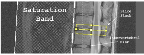
[image:2.612.308.548.241.333.2]MR spine imaging has been widely used for noninva-sive detection of different abnormalities and diseases in the spinal column, vertebrae, and intervertebral disks. This pa-per focuses on setting up transverse image acquisition for diagnosis of intervertebral disk pathologies. In typical MR spine imaging cases, a patient is initially scanned to obtain a set of T2-weighted sagittal images or coronal localizer im-ages. If an abnormality of an intervertebral disk is found, a transverse scan is then performed. The orientation of the transverse images is planned parallel to the major axis of the disk and the center of the transverse images is located on where the disk joins the spinal cord. A saturation band is placed to suppress strong MR signals from abdominal ves-sels and should not overlap with the spinal column (see Fig-ure 1). Currently transverse imaging planning is done man-ually. The process, however, is time-consuming and sub-ject to intra- or inter-operator variation. Therefore there is a salient need for automation in transverse imaging planning.
Figure 1. Sagittal view of the vertebral col-umn. The orientation of the intervertebral disk is used to set up the slice stack.
This requires accurate and consistent detection of interver-tebral disk orientation and an approximate segmentation of vertebrae. This paper presents a semi-automatic computer-based technique to detect intervertebral disk orientation ac-curately and to approximate vertebrae by rectangles.
Ideally, the first step in detecting the orientation of an intervertebral disk is to detect the boundaries, or segmen-tation, of the disk itself. However, this is difficult if there is an abnormality or there are weak or missing boundaries. However, the boundary of the intervertebral disk is closely aligned with the boundaries of the rigid vertebrae it sepa-rates. Therefore, we can infer the intervertebral disk ori-entation by finding the bounding edges of its adjacent ver-tebrae. Since each vertebrae can be geometrically approx-imated by a rectangle, we incorporate this a priori shape constraint into our approach to increase the robustness of the solution.
1.1
Related work
ac-quire relatively clear images of the spine without the radia-tion risk, and is the modality of choice for studying interver-tebral disk pathologies. Several authors [1, 2] present seg-mentation approaches with experiments using this modality. Given the difficulty of vertebrae segmentation problem, it is desirable to further constrain the solution space. Rather than represent each vertebra as an arbitrary contour, re-searchers have employed shape templates [3, 5], Fourier de-scriptors [8], as well as active shape models for individual vertebrae [1] or the entire spinal column [6] built from train-ing data. In this paper, we approximate each vertebra as a rectangle, computed as a semi-affine transformation applied to the unit square. Indeed, for the estimation of interver-tebral disk orientation, exact vertebrae segmentation is not necessary since we are interested in the direction of the ver-tebral edges that are aligned with the disk. Unlike standard active contour methods, the speed function of the contour is integrated along the perimeter of the rectangle, resulting in a rectangle evolution that is more robust to local variations in the speed function and initial placement. This enhances consistency in the results, an important feature for clinical use.
1.2
Our contribution
The method presented in this paper is motivated by the work of Yezzi et al. in [7], which performs simultaneous registration and segmentation of the same object in multiple images that may be acquired by different imaging modali-ties. However, in this work, we impose the shape constraint of a rectangle by mapping the unit square into the image using a semi-affine transformation. Rectangles are used to segment adjacent vertebrae on the same image rather than using arbitrary contours to segment the same object in dif-ferent images. In addition, we present interaction forces designed to penalize larger variations in scale and rotation, under the assumption that adjacent vertebrae have a similar size and orientation. Finally, unlike standard level set im-plementations, our resulting mathematical model is based on ordinary differential equations (ODEs) instead of partial differential equations (PDEs). This allows us to take larger time steps in our numerical implementation.
2
Method
2.1
Active rectangle representation
Let I : Ω ⊂ R2 → R denote the image of the
unit square, formed as a closed polyline with an outward-oriented normalN, as depicted on the left of Figure 2, and letIˆ: ˆΩ ⊂ R2 → Rbe the target MR image. The unit
squareCis mapped fromItoIˆasCˆusing a transformation
[image:3.612.315.547.75.177.2]g : R2 → R2, i.e., Cˆ = g(C). The mappingg consists
Figure 2. Our atlas shape in image I is the unit square (left), transformed as a rectangle into the imageIˆ(right) by a semi-affine trans-formationg(x).
of registration parameters,g1· · ·gn, which in this paper are
a set ofn= 5parameters from a finite-dimensional group represented by a rotation angleθ, non-uniform scale param-etersMx,My, and displacement parametersDx, andDy. These are used in a semi-affine transformation given as
ˆ
x=g(x) =RMx+D, (1)
with rotation matrixR =
cosθ sinθ
−sinθ cosθ
, scaling
ma-trix M =
Mx 0
0 My
, and translation vector D =
[Dx, Dy]T, andx is a point on the unit square. Figure 2 depicts the transformation of the unit square into the MR image.
2.2
Energy function and curve evolution
Segmentation can be achieved by following a gradient descent procedure to minimize a region-based energy func-tional of the form:
E(g) =
Z
ˆ
Cin
ˆ
fin(ˆx)dxˆ+
Z
ˆ
Cout
ˆ
fout(ˆx)dˆx (2)
where fˆis a function that best represents a certain char-acteristic of the image such as the mean or variance. We chose the piecewise constant segmentation model of Chan and Vese [4], for whichfˆin= ( ˆI−ˆu)2andfˆout= ( ˆI−ˆv)2,
whereuˆandˆv are the mean values inside and outside the segmenting curve respectively. We re-express this func-tional on the domainΩas
E(g) =
Z
Cin
(|g0|fˆin◦g)(x)dx+
Z
Cout
(|g0|fˆout◦g)(x)dx
Taking the derivative of Equation 3 with respect to the registration parameter gi gives the following gradient de-scent minimization,
dgi dt =
∂E ∂gi =
Z
C
ˆ
f(g(x))
∂g(x)
∂gi , mRM −1N
ds, (4)
wheregi indicates one element ofg, m = MxMy, fˆ = ( ˆfin−foutˆ ), andhiindicates an inner product. Details of this flow can be found in [7]. Intuitively, equation (4) is an ODE whose solution requires us to traverse the contour of the unit square, shown in Figure 2, find its new transformed pose in the image, then update the pose functionguntil con-vergence. That is, the segmentation occurs by updating the registration parametersgi· · ·gn. Unlike [7], there is no con-tour update∂C∂t since our contour in domainΩis fixed as the unit square.
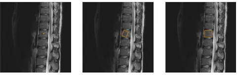
[image:4.612.56.297.380.456.2]To avoid misalignment due to salient features away from the disk, we apply a weighting (empirically set to 4.0) to the edges of the transformed square that are closest to the intervertebral disk. These edges have a similar orientation as the disk itself. For initialization, the algorithm sets the translation to the starting pointxˆin the MR image, the ro-tation angle to 0 and the scale parameters to 1. An example evolution for a single rectangle appears in Figure 3.
Figure 3. Evolution of a single rectangle. From left to right: 0, 25, and 100 iterations, using time step∆t= 0.5.
2.3
Interaction forces
While it is possible to independently evolve rectangles in each vertebra adjacent to an intervertebral disk, we can take advantage of the similarity of adjacent vertebrae to further constrain the problem. Under the assumption that adjacent vertebrae have a similar size and orientation, we propose an interaction energy between adjacent rectangles. This energy penalizes large orientation and scale differences, and takes the form E(g) = f(∇gi), where f(z) is a differentiable
function that penalizes the variation of the registration pa-rameters of different active rectangles. Differentiation of
E(g)with respect togiyields the interaction force
dgi dt =
∂E ∂gi =
∂f ∂z
∂z
∂gi (5)
We have investigated several forms of the penalty function; however, due to space constraints we only present one func-tion here, namelyf(z) = 1
2z
2, which provides sufficient
regularization on the registration parameters. We evolve in the negative gradient direction, yielding the update
dgi
dt =−α∆gi, (6)
where∆is the Laplacian operator andαis a constant used to weight the influence of the interaction force. In all our experiments, we setα = 0.25, which has provided suffi-cient coupling for our data between adjacent active rectan-gles to jointly perform the segmentation. However, using a lower value ofαwould decrease the coupling, which could be desirable if the adjacent vertebrae had larger differences in size/orientation.
[image:4.612.314.547.382.454.2]An example comparing independent vs. coupled seg-mentation is presented in Figure 4. For the left and mid-dle of the figure, we performed independent evolutions of the two rectangles starting from different initial conditions (seed points), resulting in the active rectangles being at-tracted to undesirable local minima. On the right we show the coupled segmentation (both sets of initial conditions produced the same result), which achieves a more robust segmentation.
Figure 4. Effect of the interaction force. Left and middle: uncoupled segmentation. Right: coupled segmentation.
3
Results
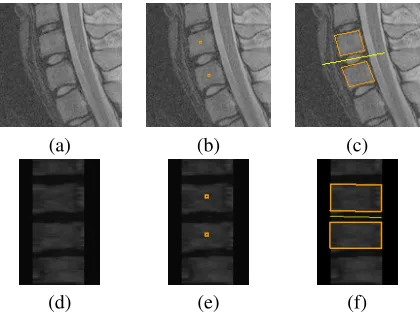
the bounding box connecting the detected vertebrae (clini-cally, manual determination of the orientation is done in a similar fashion). The upper part of Figure 6 shows the result for a sagittal C-Spine image, and the lower part of the figure shows an example for a coronal image. Computing the disk orientation in both the sagittal and coronal views defines a plane that is used for setting up the transverse slice stack. All segmentations complete within a few seconds.
Figure 5. Segmentation approach. Origi-nal image (a), seeds overlaid (b), and fiOrigi-nal segmentation result (c) with disk orientation drawn as a line between vertebrae.
(a) (b) (c)
(d) (e) (f)
Figure 6. More examples. Saggital C-spine re-sult (a) - (c), and coronal rere-sult (d) - (f).
For validation of the proposed method, we used it to de-termine the orientation of 51 intervertebral disks, coming from 9 different patients. Since ground truth is not avail-able, we compared these orientation results to those esti-mated by hand, achieved by a user drawing a line over the disk indicating its orientation. The results of these exper-iments were that on average, the algorithm computed the disk orientation to less than2.25degrees of that detected by a human operator.
4
Conclusion and future work
In this paper we presented a simple and efficient method to detect the orientation of intervertebral disks. The method fits a rectangle to each adjacent vertebrae by minimizing an energy functional based on a shape constraint, image data, and coupling between adjacent rectangles. While more comprehensive validation of the algorithm is required, from our experimental results we conclude that the shape con-straint combined with the coupled segmentation results in good vertebrae segmentation from which the intervertebral disk orientation can be computed.
Since our method uses gradient descent to minimize an energy functional, it achieves a local minimum of the en-ergy, and can produce different results for different initial-izations, which is typical for this class of methods. When the vertebrae are imaged so that they have a consistent in-tensity and their borders have sufficient contrast, our seg-mentation method typically converges to a reasonable solu-tion. However, for robustness it is certainly possible to in-clude other image statistics (beyond the Chan-Vese model we employ) in our framework. This is left for future work.
The framework presented in this paper is quite gen-eral in that any shape representable by a closed polyline is supported. For future work, we are interested consid-ering other segmentation problems with different problem-specific shape constraints, as well as extending the method to polyhedra in 3D space.
References
[1] M. Brejl and M. Sonka. Object Localization and Border De-tection Criteria Design in Edge-Based Image Segmentation: Automated Learning from Examples. IEEE Transactions on Medical Imaging, 19(10):973–985, 2000.
[2] J. Carballido-Gamio, S. J. Belongie, and S. Majumdar. Nor-malized Cuts in 3-D for Spinal MRI Segmentation. IEEE Transactions on Medical Imaging, 23(1):36–44, 2004. [3] C. Cardan and R. Allen. Measurement of Spine Motion for
Diagnosis of Mechanical Problems. InJ. Simulation Model-ing Med., volume 1, pages 15–19, 2000.
[4] T. Chan and L. Vese. Active Contours Without Edges. IEEE Transactions on Image Processing, 10(2):266–277, 2001. [5] C. Simonis and R. Allen. Determination Of Instantaneous
Centres Of Rotation: Parallel Application In Spine Kinemat-ics. InProc. IEEE Conference on Engineering in Medicine and Biology Society, volume 1, pages 39–40, 1992.
[6] P. P. Smyth, C. J. Taylor, and J. E. Adams. Automatic mea-surement of Vertebral Shape Using Active Shape Models. Im-age and Vision Computing, 15:575–581, 1997.
[7] A. Yezzi, L. Z¨ollei, and T. Kapur. A Variational Framework for Integrating Segmentation and Registration Through Ac-tive Contours.Medical Image Analysis, 7:171–185, 2003. [8] Y. Zheng, M. S. Nixon, and R. Allen. Automated
[image:5.612.64.274.380.538.2]