TRACKING PERFORMANCE OF A HOT AIR BLOWER SYSTEM USING PID CONTROLLER WITH PSO AND HARMONIC SEARCH ALGORITHM
ANDY HENG POH SENG
This Report Is Submitted In Partial Fulfillment Of Requirements For The Bachelor Degree Of Electronic Engineering (Industrial Electronics) With Honors
Fakulti Kejuruteraan Elektronik dan Kejuruteraan Komputer Universiti Teknikal Malayasia Melaka
iii
v
vi
ACKNOWLEDGEMENT
First and foremost, I would like to express my deep gratitude to my supervisor, Puan Siti Fatimah Binti Sulaiman and Puan Sharatul Izah Binti Samsudin for her advice and guidance throughout the completion of this project. This project will not complete without the help, support and words of encouragement from her. Thank you.
Next, I would like to thanks my family members for giving me their physical and mental support during this project and my four years study in University Teknikal Malaysia Melaka.
Special thanks to my friends, Lim Hooi Chen and Lee Kian Loong who are under the same supervisor for supporting and encourage me throughout this project. This project could not be done without them. Suggestion and criticism from my friends have always drives me to make improvement to the project.
vii
ABSTRACT
viii
ABSTRAK
ix
CONTENTS
CHAPTER CONTENTS PAGE ACKNOWLEDGEMENT vi
ABSTRACT vii
ABSTRAK viii
CONTENTS ix-xi LIST OF FIGURES xii-xiv
LIST OF TABLES xv
LIST OF SYMBOLS xvi
LIST OF ABBREVIATIONS xvii
LIST OF APPENDICES xviii
I INTRODUCTION
x
II LITERATURE REVIEW
2.1 PT326 Process Trainer 5-7 2.2 Description 7-9 2.3 System Identification 9 2.3.1 Introduction of System Identification 10-12 2.3.2 System Identification Procedures 12-13 2.4 Proportional-Integral-Derivative (PID) 13-15 Controller
2.5 Ziegler-Nichols Tuning Method 15-16 2.6 Particle Swarm Optimization (PSO) 16-20 Tuning Method
2.7 Harmonic Search Algorithm (HSA) 20 Tuning Method
2.7.1 Steps of Harmony Search Algorithm 20-21
III METHODOLOGY
3.1 Chapter Overview 22 3.2 Block Diagram 22-23 3.3 Method Implementation Flowchart 23-25 3.4 System Identification Process 26
3.4.1 Input and output data 26-33 3.4.2 Model structure selection 33-34 3.4.3 Parameter Estimation 35-36 3.4.4 Model validation 36
3.4.4.1 Best fit 36-37
xi
3.4.4.3 Akaike‟s final prediction error 38-39 (FPE)
3.4.4.4 Poles and zero plot 39-40 3.5 PID Controller Design 40
3.5.1 ZN-PID Controller 41 3.5.2 PSO-PID Controller 41 3.5.3 HSA-PID Controller 42 3.6 Evaluation of the Controller Performances 42
IV RESULT AND DISCUSSION
4.1 System‟s Response (Without Controller) 43-45 4.2 Proportional-Integral-Derivative (PID) 45-53
Controller
V CONCLUSION AND RECOMMENDATION
5.1 Conclusion 54
5.2 Future Works 54-55
REFERENCE 56-57
xii
LIST OF FIGURES
FIGURE NO. TITLE PAGE
Figure 2.1 PT326 Process Trainer 6 Figure 2.2 Basic Element of PT326 Process Trainer 7 Figure 2.3 Input, output and disturbance relationships 10 in system identification
Figure 2.4 Flow chart System Identification Approach 11 Figure 2.5 Block diagram of PID 14
Figure 2.6 Bird flock 17
Figure 2.7 Gbest and Pbest converge curve 17 Figure 3.1 Block diagram of Hot Air Blower System 23
using PID Controller, PSO and HSA
Figure 3.2 Flow chart of the project 24-25 Figure 3.3 System Identification Tool GUI window 27 Figure 3.4 The Import Dialog box 28 Figure 3.5 mydata icons in System Identification Tool 28
GUI
Figure 3.6 The Time Plot window 29 Figure 3.7 The updated Time Plot window (after 30
“remove means” process)
xiii
Figure 3.9 Selected ranges for model estimation 31 Figure 3.10 mydatade icons added in System Identification 31
Tool GUI
Figure 3.11 Selected ranges for model validation 32 Figure 3.12 mydatadv icons added in System Identification 32
Tool GUI
Figure 3.13 mydatade and mydatadv icons added in System 33 Identification Tool GUI
Figure 3.14 Selection of linear parametric models 34 Figure 3.15 ARX model structure 34 Figure 3.16 The icons of selected model orders appeared in 35
Model Views box
Figure 3.17 Measured and simulated output of ARX 233 37 Figure 3.18 ARX 233 data or model info 38 Figure 3.19 ARX 233 zero and poles plot 40 Figure 4.1 Simulink block diagram of the validated plant 44
model (without controller)
Figure 4.2 The output response of the validated plant 44 model (without controller)
Figure 4.3 Output responses of PID controller using 45 Ziegler Nichols tuning method
Figure 4.4 Comparison of Inertia Weight using Particle 46 Swarm Optimization (PSO) tuning method
Figure 4.5 Comparison number of particle using Particle 47 Swarm Optimization (PSO) tuning method
Figure 4.6 Output responses of PID controller using 48 PSO tuning method
Figure 4.7 Comparison number of particle using Harmonic 49 Search Algorithm (HSA) tuning method
xiv
HSA tuning method
xv
LIST OF TABLES
TABLE NO. TITLE PAGE
Table 2.1 Ziegler-Nichols Table 16 Table 3.1 Akaike‟s Model Validity Criterion value 39
based on ARX 233 model structure
Table 3.2 Updated value of and using 41 Ziegler Nichols tuning method
Table 3.3 Best value of and using PSO 41 tuning method
Table 3.4 Best value of and using HSA 42 tuning method
Table 4.1 The value of parameter and value 46 of the Peak time, Settling time and Percentage
Overshoot using Ziegler-Nichols tuning method Table 4.2 The value of parameter and value 48 of the Peak time, Settling time and Percentage
Overshoot using PSO tuning method
Table 4.3 The value of parameter and value 51 of the Peak time, Settling time and Percentage
Overshoot using HSA tuning method
Table 4.4 Performances of the PID controller designed 52 using Ziegler-Nichols, PSO and HSA
xvi
LIST OF SYMBOLS
- proportional gain
- integral gain
- derivative gain
z - discrete form
xvii
LIST OF ABBREVIATIONS
GUI - Graphic User Interface
PID - Proportional Integral Derivative
ZN - Ziegler-Nichos
PSO - Particle Swarm Optimization HSA - Harmonic Search Algorithm
ARX - Auto Regressive with Exogenous Input FPE - Akaike‟s Final Error
AIC - Akaike‟s Information Criterion
xviii
LIST OF APPENDICES
APPENDIX TITLE PAGE
A PID Controller (Using Ziegler-Nichols 58 tuning method)
CHAPTER 1
INTRODUCTION
1.1 Overview
2
performance of the process temperature using Particle Swarm Optimization and Harmonic Search Algorithm.
So to achieve the highest performance of the PT326 hot air blower system, PID controller needs to be designed. The best mathematical model of the system is necessary required for the controller design so that the system is under control. Consequently, the mathematical model of the PT326 process using System Identification approach was considered in this work. System Identification Toolbox in MATLAB is used to make estimation for the parameters. Besides, it is also used to approximate the system models based on the mathematical models obtained. There are two methods in System Identification Approach that used to describes the mathematical models of the system, and the two methods which are parametric and non-parametric method. Moreover, AutoRegressive with Exogenous Input (ARX) is selected as the model structure of this project to do estimation and validation of the model system. To ensure the ARX model structure obtained either accepted or rejected, the Model Validation Criterion was used. Once the model structure was accepted and the model system was validated, the PID controller is designed to improve the output response of the system. Three different tuning methods: Ziegler-Nichols, Particle Swarm Optimization (PSO) and Harmonic Search Algorithm (HSA) are proposed in this work.
1.2 Objectives
The objectives of this project are:
1. To determine the mathematical model of the PT326 process trainer using System Identification Approach.
2. To estimate and validate the parameters of the PT326 mathematical model using ARX model structure.
3
4. To apply PSO and Harmonic Search Algorithm in PID controller for the purpose of tuning the parameter.
5. To make a comparison and justification based on the controller performance obtained from the simulation.
1.3 Problem Statement
The development of this project is based on these problems:
1. Unknown plant model or mathematical model of the PT326 process trainer.
2. Unknown suitable parametric approach or model structure to be used to estimate the mathematical model of a particular system.
3. Undesired output response of the system.
1.4 Scope of work
4
1.5 Thesis Outline
Chapter 1 is the part of introduction. In this part, introduction was included to briefly explain some important parts of the whole project, objective of project, problem statement of project and scope of work.
Chapter 2 represents the part of literature review. In this part, review on the related journal, books and internet resources will be done. This is due to study the related project in order to obtain the smallest possible value for the rise time, overshoot, settling time and steady state error by using the PID Controller.
Chapter 3 represents the methodology. In this chapter, the overall design and methods to apply in this study had been stated. The main methodology that been stressed out related to the PID Controller and data collection from the MATLAB simulation.
Chapter 4 shows the part of result and discussion. In this chapter, simulation result and discussion of this project is discussed in this chapter. The simulation results of the system performance have been observed. Besides, the implementation of PID Controller using Particle Swarm Optimization (PSO) and Harmonic Search Algorithm will be done in order to achieve the objectives. Discussion also be done discuss about the problem faced along the project.
5
CHAPTER 2
LITERATURE REVIEW
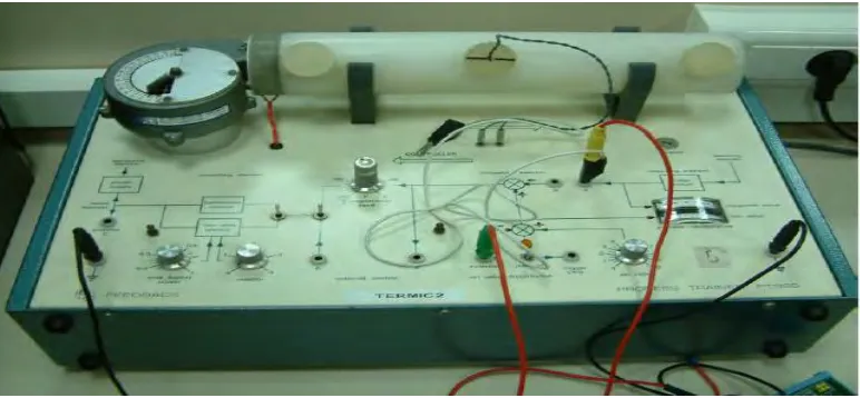
2.1 PT326 Process Trainer
6
Figure 2.1: PT326 Process Trainer