UNIVERSITI TEKNIKAL MALAYSIA MELAKA
Field Oriented Control of Five-phase Induction Motor Speed Drive
Using DSpace and Matlab/Simulink
This report is submitted in accordance with requirement of the Universiti Teknikal Malaysia Melaka (UTeM) for the Bachelor’s Degree in Electrical Engineering
Technology (Industrial Power) with Honors’
By
ANMAR SARHAN BIN RAZLAN B071410597
921129-06-5021
ii
FAKULTI TEKNOLOGI KEJURUTERAAN
Tel: +606 234 6623 | Faks : +606 23406526
Rujukan Kami (Our Ref) : Rujukan Tuan (Your Ref) :
13 DISEMBER 2017
Pustakawan Perpustakaan UTeM
Universiti Teknikal Malaysia Melaka Hang Tuah Jaya, 76100 Durian Tunggal, Melaka.
Tuan/Puan,
PENGKELASAN LAPORAN PSM SEBAGAI SULIT/TERHAD LAPORAN PROJEK SARJANA MUDA TEKNOLOGI KEJURUTERAAN ELEKTRIK (BETI): ANMAR SARHAN BIN RAZLAN
Sukacita dimaklumkan bahawa Laporan PSM yang tersebut di atas bertajuk
“FIELD ORIENTED CONTROL OF FIVE PHASE MOTOR SPEED DRIVES USING DSPACE AND MATLAB/SIMULINK” mohon dikelaskan sebagai
*SULIT / TERHAD untuk tempoh LIMA (5) tahun dari tarikh surat ini.
2. Hal ini adalah kerana IANYA MERUPAKAN PROJEK YANG DITAJA OLEH SYARIKAT LUAR DAN HASIL KAJIANNYA ADALAH SULIT.
Sekian dimaklumkan. Terima kasih.
Yang benar,
Tandatangan dan Cop Penyelia
iii
DECLARATION
I hereby, declared this report entitled “FIELD ORIENTED CONTROL OF FIVE PHASE MOTOR SPEED DRIVES USING DSPACE AND MATLAB/SIMULINK”
is the results of my own research except as cited in references.
Signature : ……….
Author’s Name : ………
iv
APPROVAL
This report is submitted to the Faculty of Engineering Technology of UTeM as a partial fulfillment of the requirements for the degree of Bachelor of Electrical Engineering Technology (Industrial Power) with Honors’. The member of the supervisory is as follow:
v
ABSTRAK
vi
ABSTRACT
vii
DEDICATION
viii
AKNOWLEDGEMENT
ix
Table of Contents
APPROVAL ... iv
ABSTRAK ... v
ABSTRACT ... vi
DEDICATION ... vii
AKNOWLEDGEMENT ... viii
LIST OF FIGURES ... xi
LIST OF ABBREVIATIONS, SYMBOLS AND NOMENCLATURE ... xiv
CHAPTER 1 ... 1
INTRODUCTION ... 1
1.0 Project Overview ... 1
1.1 Motivation ... 1
1.2 Problem Statement ... 2
1.3 Project Objective ... 2
1.4 Project scope ... 3
1.5 Report Outline... 3
CHAPTER 2 ... 5
LITERATURE REVIEW ... 5
2.0 Introduction ... 5
2.1 Induction Motor ... 6
2.2 Five-Phase Induction Motor ... 6
2.3 Inverter ... 7
2.4 Five-phase inverter ... 8
2.5 Gate drive ... 8
2.6 Insulated Bipolar Junction Transistor (IGBT) ... 9
2.7 DSpace... 10
2.8 Matlab/Simulink ... 11
CHAPTER 3 ... 13
METHODOLOGY ... 13
3.0 Introduction ... 13
x
3.2 Induction Motor ... 16
3.3 Inverter... 17
3.4 Gate driver ... 19
3.5 Controller ... 20
3.5.1 For this project DSpace is used because: ... 21
3.5.2 The purpose used as five-phase induction motor controller: ... 23
3.5.3 For complete real-time control system building with just one controller board: ... 24
3.6 Measurement ... 25
3.7 High Voltage Probe ... 27
3.8 Field-Oriented Control ... 27
3.9 Speed Controller ... 28
3.10 Topology of inverter ... 29
3.11 Implementation of hardware ... 29
3.11.1 Oscilloscope ... 30
3.11.2 Direct Current Power Supply ... 31
3.11.3 DSpace ... 32
3.11.4 Controller DSpace ... 33
3.11.5 Insulated Bipolar Junction Transistor... 34
3.11.6 High Voltage Differential Probe ... 35
3.11.7 Direct Current Probe ... 36
3.9 Expected Result ... 37
CHAPTER 4 ... 38
RESULT AND DISCUSSION ... 38
4.1 Introduction ... 38
4.2 Result from the simulation and experimentation ... 39
4.2.2 Field Oriented Control ... 40
4.3 Result from Matlab/Simulink simulation ... 41
4.3.1 Stator Current for all phase ... 41
CHAPTER 5 ... 53
xi
LIST OF FIGURES
Figure 2.1: Total system block diagram 5
Figure 2.2: Waveform DC to AC 7
Figure 2.3: Five-phase inverter connected to five-phase induction
motor with DC source and input 8
Figure 2.4: Opto-Coupler Gate Driver Example 9
Figure 2.5: IGBT equivalent circuit 10
Figure 2.6: IGBT symbol 10
Figure 2.7: Matlab Software 11
Figure 3.1: Flowchart of project 14
Figure 3.2: Flow chart to control induction motor 15 Figure 3.3: Example of induction machine in Matlab/Simulink 16
Figure 3.4: Shows actual induction motor 17
Figure 3.5: Inverter switching concept 17
Figure 3.6: Five-phase inverter in Matlab/Simulink and under mask which is detailed view of five-phase inverter. 18
Figure 3.7: Gate drive schematic 20
Figure 3.8: Hardware circuit for gate drive using opto-coupler 20 Figure 3.9: DSpace controller in Central Processing Unit (CPU) 23
xii
Figure 3.12: This block is to measure the voltage in Matlab/Simulink
simulation 27
Figure 3.13: Field Oriented Control block in Matlab 27
Figure 3.14: AC speed controller in Matlab 28
Figure 3.15: Shows an Oscilloscope. 30
Figure 3.16: DC Power Supply. 31
Figure 3.17: DSpace 32
Figure 3.18: Shows a controller DSpace 33
Figure 3.19: Insulated Bipolar Junction Transistor attach to heatsink 34
Figure 3.20: High Voltage Differential Probe 35
Figure 3.21: Current probe. 36
Figure 4.1: The simulation block of the motor speed controller 39
Figure 4.2: Field Oriented Control Modelling 40
Figure 4.3: Stator Current for All Phase 41
Figure 4.4: Stator Current for Phase A 42
Figure 4.5: Stator Current for Phase B 43
Figure 4.6: Stator Current for Phase C 43
Figure 4.7: Stator Current for Phase D 44
Figure 4.8: Stator Current for Phase E 44
Figure 4.9: Motor Speed at 300. 45
xiii
Figure 4.11: Torque 46
Figure 4.12: Actual Stator Current Phase A 47
Figure 4.13: Actual Stator Current Phase B 47
Figure 4.14: Actual Stator Current Phase C 48
Figure 4.15: Actual Stator Current Phase D 48
Figure 4.16: Actual Stator Current Phase A 49
Figure 4.17: Voltage 50
xiv
LIST OF ABBREVIATIONS, SYMBOLS AND
NOMENCLATURE
AC - Alternate Current
BJT - Bipolar junction transistor CPU - Central Processing Unit CRT - Cathode Ray Tube DC - Direct Current
FOC - Field Oriented Control GUI - Graphic User Interface
IGBT - Insulated Gated Bipolar Transistor
MOSFET - Metal-Oxide Semiconductor Field Effect Transistor PWM - Pulse Width Modulation
RMS - Root Mean Square
1
CHAPTER 1
INTRODUCTION
1.0 Project Overview
This project, rely on control of five-phase motor using Field Oriented Control (FOC) using MATLAB simulation and DSpace. Nowadays, controlling speed of five phase motor becomes important aspect in many industries. The main objective of motor speed control is to keep motor at desired speed. In this project, DSpace will control five-phase induction motor. DSpace act as controller for fast voltage and current measurement. The DSpace is digital signal processor that will be connected to computer and will operated in real time. DSpace will connect to drive hardware and to motor using DSpace connector. DSpace also will control the parameter that tuned in computer. For speed, the project varies the frequency by using FOC by using of an inverter. The switching scheme will be applied to an inverter. The sinusoidal pulse width modulation switching scheme have used to find the signal. The FOC is used for switching the inverter to drive five-phase induction motor.
1.1 Motivation
2
harmonics become lower. This project will use five-phase inverter as motor drive power supply. MATLAB software is used for controling the speed of five- phase induction motor. With this software, designation of five-phase motor speed controller will be done. DSpace will acts as interfaces to control the motor speed.
1.2 Problem Statement
The contemporary advance in the area of FOC bring the fast development and cost saving of power electronic devices for five-phase induction motor give more cost-effective for numerous industrial applicants. However due to complexity of induction motor will cause problem. Several parameters such as load torque, rotor and stator resistance may vary significantly during operation. In this ventured the main issued is control speed of induction motor as fast response. As countermeasure, the suitable controller and drive must be design to improve the efficiency of motor to use. This ventured is to vary frequency source, the converter is needed to the source of frequency.
1.3 Project Objective
This project is triggered by a problem in controlling a five-phase induction motor speed and torque. Controlling Alternating Current (AC) five-phase motor can be quite challenging. We can use some of different technique such Pulse Width Modulation (PWM), FOC, Vector Space Modulation (VSM). So, this venture is work on controlling motor speed using MATLAB/Simulink and DSpace. In order to achieve the objective few things need to be accomplished before the project can be done:
1. Design a five-phase AC induction motor drive with low stator current using Field Oriented Control to control the motor speed
3
3. Run experimental five-phase AC motor drive and its speed controller using DSpace to analyze the mechanical and electrical performance in real time environment
1.4 Project scope
This project will be undertaken in some stages that will make this project success. First thing is to study five-phase induction motor. This will help to understanding how this system working. Firstly, create the motor drive. Then, participate the digital implementation on DSpace. Finally, to analyze performance of motor run due on simulation result and experimental result.
1.5 Report Outline
This report contains five chapters that explain in the aspect of whole project to deliver understanding of the whole project.
Chapter 1- Project Introduction
This chapter offerings an overview of the project, project motivation, problem statement, project objective, project scope and expected project outcome.
Chapter 2- Literature Review
This chapter deliberates about source and article that related to the project. This chapter also comprehends the system of the component, equipment and programming that used in the project. This will help to understanding the concept of the project.
4
This chapter covers up all the project application to achieve the objective of the project. This chapter contains the technique and procedures to complete the project. It also contains the step taken for entire task to comprehensive the project. All method and procedure to generate the expected results and the software technical detail also explained in this chapter.
Chapter 4 – Result and discussion
This chapter comprehend the result and analysis of the project that been done. the result and expected result also discuss in this chapter.
Chapter 5 –Conclusion
5
CHAPTER 2
LITERATURE REVIEW
2.0 Introduction
This chapter briefly discusses the five-phase AC motor characteristic and part. Then, will explain about inverter and its function and component. It also will discuss about development of five- phase AC motor drive using MATLAB/Simulink. Many theories have been proposed to develop AC controller and motor drive. With this study we must carried out how to develop and make improvement in AC controller and motor drive. Although, the literature includes many theories, this study will be focused on development of AC controller and motor drive using MATLAB/Simulink and DSpace as interface. However other information from past researcher will also be included in this chapter for the reader to understand more in this project.
AC Rectifier Inverter Five-phase Induction
Motor FOC Driver
PID
[image:19.612.124.542.428.623.2]REF Speed, Voltage ,Current
6
2.1 Induction Motor
Induction motor is very general and extensively used in electrical industry. Induction motor will run at constant speed from no load to full load. However, these motors depend on frequency to control the speed. This characteristic makes the motor runs at constant speed because the speed can’t have changed easily. This factor make the DC motor is better in term dealing with speed variation. According to R. H. Sagor [1] induction motor is simple, durable, low prices, easy to maintain and can be made features to suit most requirement of the industries. According to F. Semiconductor [2], the most popular type is the 3-phase, squirrel cage AC induction motor. It is maintenance-free, less noisy and efficient motor.
2.2 Five-Phase Induction Motor
7
2.3 Inverter
[image:21.612.140.516.215.364.2]Inverter is an electronic devices or circuitry that changes direct current (DC) to alternate current (AC). This equipment is widely used in electrical system and commonly found on electrical generation system. A power inverter can be entirely electronic or may be combination of mechanical effect and electronic circuitry.
Figure 2.2: Waveform DC to AC
8
2.4 Five-phase inverter
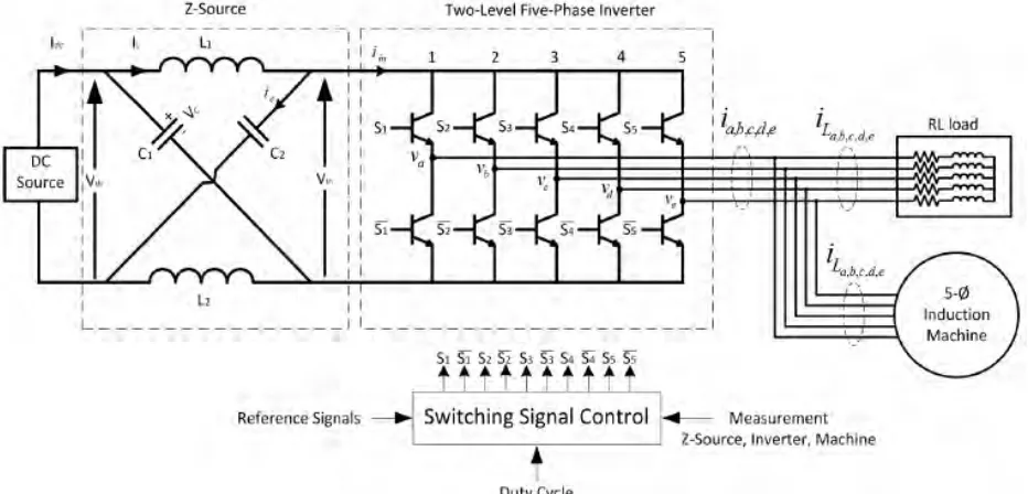
[image:22.612.116.582.296.520.2]This ventured is using of the five-phase inverter plays an important role to ensure these projects succeed. Five-phased is inverter work at line frequency, which the main output power. William R. Finley [6] stated that, the switch work at line frequency, so the switching loss is small and the efficiency of output power system is high. Five- phase full bridge inverter is used to improve system dynamic performance. Compared to traditional inverter circuit, higher efficiency can be achieved and at the same times harmonics will be low and voltage stress of power switches also can be reduce. Circuit can be control easily and also easy to modularized.
Figure 2.3: Five-phase inverter connected to five-phase induction motor with DC source and input
2.5 Gate drive
9
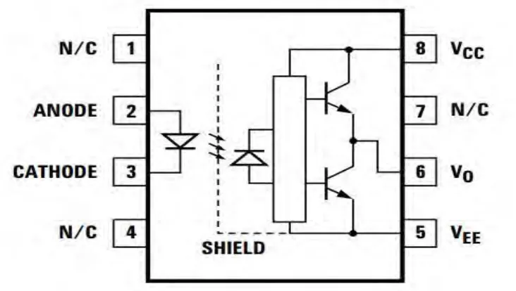
[image:23.612.118.484.146.353.2][7] stated that gate drives are and interface that accepts a low power input from a controller and produces a high current drive input for the gate power of high power IGBT.
Figure 2.4: Opto-Coupler Gate Driver Example
2.6 Insulated Bipolar Junction Transistor (IGBT)
10
Figure 2.5: IGBT equivalent circuit
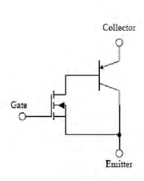
Figure 2.6: IGBT symbol
2.7 DSpace