ISSN: 2252-8938 149
Takagi-Sugeno Fuzzy Perpose as Speed Controller in Indirect
Field Oriented Control of Induction Motor Drive
Roslina Mat Ariff1, Dirman Hanafi1, Wahyu Mulyo Utomo2, Nooradzianie Muhammad Zin2, Sy Yi Sim2, Azuwien Aida Bohari2
1
Department of Mechatronic and Robotic, University Tun Hussein Onn Malaysia
2
Department of Power Electrical, University Tun Hussein Onn Malaysia
Article Info ABSTRACT
Article history: Received Aug 15, 2016 Revised Oct 19, 2016 Accepted Nov 22, 2016
This paper deal with the problem in speed controller for Indirect Field Oriented Control of Induction Motor. The problem cause decrease performance of Induction Motor where it widely used in high-performance applications. In order decrease the fault of speed induction motor, Takagi-Sugeno type Fuzzy logic control is used as the speed controller. For this, a model of indirect field oriented control of induction motor is built and simulating using MATLAB simulink. Secondly, error of speed and derivative error as the input and change of torque command as the output for speed control is applied in simulation. Lastly, from the simulation result overshoot is zero persent, rise time is 0.4s and settling time is 0.4s. The important data is steady state error is 0.01 percent show that the speed can follow reference speed. From that simulation result illustrate the effectiveness of the proposed approach.
Keyword:
Indirect Field Oriented Control Induction Motor
Takagi- sugeno type fuzzy logic control
Copyright © 2016 Institute of Advanced Engineering and Science. All rights reserved.
Corresponding Author: Roslina Mat Ariff,
Department of Mechatronic and Robotic, University Tun Hussein Onn Malaysia.
1. INTRODUCTION
The three-phase induction motors (IM) are very frequent used in industrial application, because of the simplicity of its implementation, higher torque-to-weight ratio, higher reliability, ruggedness and low maintenance requirements. and ability to operate in dangerous environment[1]-[3]. Because of that the performance of IM is important, in order to maintantan IM performance one of the couse is controlling part[4].
But, the coupling between torque and flux in IM unlike DC motor, their control is a challenging task. However, indirect field oriented control (IFOC) is use to decouple between torque and flux then can be controlling separately [5]-[7]. In IFOC system is using park and calack transformation equation in order to decouple flux and torque.
In this context, for developing controllers for the plant the fuzzy logic concepts play a very important no need that much complicated hardware but just used some set of rules[8]. Interface system of Takagi-Sugeno (TS) type Fuzzy are characterized by use of function of their input variable as consequents and propose in 1985.TS systems is powerful practical tool for modeling and controlling of complex systems[9]. TheThis paper present performance for IM is the output speed, so Takagi-Sugeno type of fuzzy logic control is use as the speed controller to obtain batter performance. This TS approach has been extensively used to model nonlinear systems and has been successfully applied to practical problems[10]. The basic idea from fault of the speed IM, TS is use by obtain the rule then produce the change of torque comment and decrease fault of speed.
2. INDUCTION MOTOR MODEL AND INDIRECT FIELD ORIENTED CONTROL
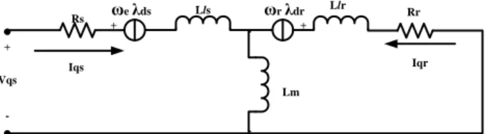
Model of IM can be obtained from their equivalent circuit of Induction Motor shown in Figure 1:
Figure 1. Per-phase Equivalent Circuit of IM
From the equivalent circuit Rs is stator resistance, Rr is rotor resistance, Lls is stator leakage inductance, Llr is rotor leakage inductance and Ls(Lr) stator(rotor) inductance [11]. Then model induction machine can be presented in synchronousd-q reference frame by the following state space model reference from that circuit [12]:
m s
s Ll L
L
,Lr Llr Lm (1)
The d-q equivalent circuit Figure 2 and Figure 3mathematical modeling of induction motor may be expressed as: Idr Iqr Ids Iqs Lr Rr Lr Lm Lm Lr Lr Rr Lm Lm Lm Lm Ls Rs Ls Lm Lm Ls Ls Rs Vds Vqs r r r r e e e e 0 0 (2)
is the derivative operation. Where Vds,Vqsare d-q axis stator voltages, Ids,Iqsare d-q axis stator
currents, Iqs,Iqsare d-q axis rotor currents, eis the speed of the rotating magnetic field and ris the rotor
speed[13].
Figure 2. Effects of Selecting Different Switching under Dynamic Condition
Figure 3. Effects of Selecting Different Switching under Dynamic Condition Rs Lls Llr Rr
Lm
Ir
Rs Lls
Llr
Rr
Lm
Iqr Iqs
ωe λds ωr λdr + -Vqs + + Rs Rr Lm Idr Ids
-ωe λqs -ωr λqr
+ +
+
-Vds
After analysing the mathematical model of IM and the principle of Indirect field-oriented vector control system, the simulation model of field-oriented control system is established. The transformation from stationary system to three-phase system ABC using Clarke Equation follows this:
c b A i i i i i 0 0 3 2 0 3 1 1 (3)
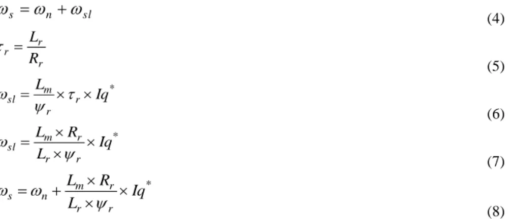
The synchronous angular velocity is often necessary in process of the phase transformation for achieving the favourable decoupling control[14]. The information of the synchronous angular velocity is important in this process. Number of different reference frames shall derive for the IM. The reference frame (α-β) or (d-q) should be chosen for state-space deputy of the asynchronous motor[15]. The (d-q) equation should be writing because it is the most complex solution and general[16]. IM in mathematical model, IFOC, be founded in (d-q) axis rotating at synchronous speed (ωs) define as follow[17]:
sl n
s
(4) r r r R L
(5) * Iq L r r m sl
(6) * Iq L R L r r r msl
(7) *Iq
L
R
L
r r r m ns
(8)From Eq. 7 will produce the theta (θ) and will be used for Park transformation and Inverse Park transformation. Theta Equation as show as below:
s
n
sl
(9)
3. PROPOSE TAKAGI-SUGENO TYPE FUZZY LOGIC CONTROL
In this paper application of fuzzy logic to the intelligent speed control of indirect vector controlled induction motor drive is investigated. The analysis, design and simulation of controller have been carried out based on the fuzzy set theory. When TS type FLC bases intelligent controller is used, excellent control performance can be achieved. Figure 4 shows the general model of a fuzzy system, which is composed of four major components[18]. Database of TS is consists of input (ip) and output (op) membership functions. The set of linguistic rule produce from rule base of TS.
Figure 4. Effects of Selecting Different Switching under Dynamic Condition
An illustration of TS system computation scheme is presented in Figure 5.
Fuzzy Rule Base
fuzzification In ference defuzzification engine
Figure 5. Illustration of TS System Computation Scheme.
The perpose of TS fuzzy type speed control is show in Figure 6.
Figure 6. Propose TSF for FOC of Induction Motor
The purpose of the FLC is use to control the speed and comprise will be dependent on the shape of the membership function (MF) to produce change of torque command (Mec). The reference q-axis current define as:
(10)
The constant flux will be use to produce the reference d-axis current using equation as follow: (11)
The reference d-q axis current will be use as input of the FOC. The FOC will be controller will produce the pattern for the Space Vector Pulse Width Modulation (SVPWM). The output from SVPWM is the input of the gate driver for the motor then connects to the inverter. The inverter will be producing the 3 phase current (abc). From the motor value that feedback to motor is speed and 3 phases current.
3.1. Design structure of Takagi-sugeno type fuzzy logic control
Structure of TS has two inputs and one output. The input is the error between actual speed and reference speed, second input is derivative error of first input. The ouput is change of torque command (Mec) and used to produce reference q-axis current in equation 10. Figure 7 show the TS simulink blockfor speed control.
rc M
r ec PL
L M Iq
2
*
M rc L Id*
Figure 7. Takagi-Sugeno Simulink Block
Figure 8 show the membership function (MF) for the first input. Range the MF is berween -1 and 1with gain 1/88. Figure 9 also show the MF but for second inpu with same range and the gain is 1/84.
Figure 8. Error Membership Function
Figure 9. Drivative Error Membership Function
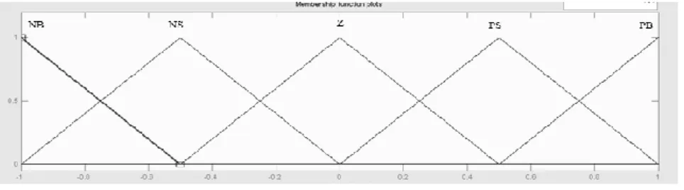
The MF output for this system show in Figure 10. Range output is -0.05 to 1with gain 260.
Figure 10. Output Membership Function
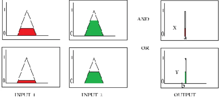
Rule for these TS propose is list in table 1. With the center of gravity (COG) equation from figure 5as reference describe:
Xa
Yb
1-0.05 0 0.2125 0.475 0.7375 1
X is the height of min MF with AND rule, a is the value in output from the rule. Y is the height of min MF with OR rule, b is the value in output from the rule.
Table 1. Rule of TS-FLC
de e
NB NS Z PS PB
NB Z Z PS PS PS
NS Z PS PS P P
Z PS P PM PM PB
PS P PM PM PB PB
PB PM PM PB PB PB
4. RESULT AND ANALYSIS
Simulation in this paper is using MATLAB investigate the performance of the Induction motor using difference type shaped of the membership function Fuzzy logic control. For simulation used the dynamic model of a three-phase induction motor of IFOC and TS- FLC. The constant load is applied for the system. The parameters for the motor are Vdc =560V, 50Hz, Poles=2, Rs=0.3Ω, Rr=0.25Ω, Ls=0.0415H, Lr=0.0412H, Lm=0.0403H, J=0.003kg-m2. To verify the performance of the proposed TS- FLC, the simulation results will show in detail for rise time (tr), settling time (ts), and steady state error (e%). The results describe speed in revolution per minute (rpm) versus time in second (s).Start-up response speed for the speed control using TS in 4s is show in figure 11.
Figure 11. The Result for Speed of Induction Motor For Takagi-Sugeno Fuzzy
The output speed of the induction motor using takagi sugeno fuzzy is 798rpm and the reference speed is 800rpm. The steady state error is about 0.01%. From the graph show the output response is no overshoot. The rise time is 0.4s and setling time also 0.4s. Figure 12 show the result for step speed reference.
Figure 12. Simulation Step Speed Reference Sing Fuzzy Logic Control Takagi-Sugeno Type.
0 0.5 1 1.5 2 2.5 3 3.5 4
0 100 200 300 400 500 600 700 800 900
time(s)
s
p
e
e
d
(
rp
m
)
Takagi-Sugeno Fuzzy
0 0.1 0.2 0.3 0.4 0.5 0.6 0.7 0.8 0.9 1
0 200 400 600 800 1000 1200
time (s)
s
p
e
e
d
(
rp
m
)
reference sugeno
Step speed reference is from 1000 rpmdecrease to 500rpm and increase to 1200rpm. The simulation result show the speed follows the reference speed. The settling time for the start up is 0.09s.The settling time for step down is 0.01s (0.3s-0.31s) and lastly the settling time for step up is 0.02s (0.6s-0.62s). Figure 13 below shows the output waveform for Electric Torque (Te).
Figure 13. Output Waveform for Electric Torque (Te)
A simulation testing shows the result for the torque of the IM show in Figure 13. The torque at the steady state is at 3Nm. The simulation result of current for the source of the IM and the output for the inverter. The current in 3 phase of is shown in Figure 14 below:
Figure 14. Output Waveform for 3 phase Current Ia, Ib and Ic
5. CONCLUSION
In this paper is proposing design of the speed control for the Field Oriented Control of the induction motor is using Takagi-Sugeno fuzzy (TSF). Base on the speed control the TSF is suitable for controlling speed because the speed responce follow the reference speed. The speed responce is has small steady state error, settling and rise time. The study can be further to fuzzy/neural corrector to increase the accuracy of the system.
ACKNOWLEDGEMENTS
This work has been supported by Center of Graduate Studies UniversitiTun Hussein Onn Malaysia and MYPHD of MYbrain15 Ministry of Higher Education.
REFERENCES
[1] R Abdessemed, AL Nemmour, VF Tomachevitch. Application Of Sugeno Flc To The Stator Field Oriented Double Fed Induction Motor Drive ( DFIM ). J. Electr. Eng., 2002; 53(11): 314–318.
[2] M Allouche, M Chaabane, M Soussi, D Mehdi. A Hajjaji. Takagi-Sugeno fuzzy sensor faults estimation of an induction motor. In 18th Mediterranean Conference on Control and Automation, MED’10, 2010: 243–248.
0 0.5 1 1.5 2 2.5 3 3.5 4
-5 0 5 10 15 20
time(s)
to
rq
u
e
(
N
m
)
0 0.05 0.1 0.15 0.2 0.25 0.3 0.35 0.4 0.45 0.5
-15 -10 -5 0 5 10 15
time(s)
c
u
rr
e
n
t
(A
)
Ia Ib Ic
[4] M Allouche, M Chaabane, M Souissi, F Tadeo. Takagi-Sugeno Fuzzy Observer Design for Induction Motors with Immeasurable Decision Variables : State Estimation and Sensor Fault Detection. Int. J. Comput. Appl., 2011; 23(4): 44–51.
[5] M Bahloul, M Souissi, M Chaabane, L Chrifi-Alaoui. Takagi Sugeno fuzzy observer based Direct Rotor Field Oriented Control of induction machine. In 3rd International Conference on Systems and Control, 2013: 419–426. [6] H Ben Zina, M Allouche, M Chaabane, M Souissi. Tracking control for induction motor using Takagi-Sugenou
approach. In 14th International Conference on Sciences and Techniques of Automatic Control & Computer Engineering - STA’2013, 2013; (1): 25–30.
[7] JA Glenn, JA Sneha. Indirect field oriented speed control of an induction motor drive using Takagi-Sugeno type of fuzzy logic controller. In 2012 International Conference on Emerging Trends in Electrical Engineering and Energy Management (ICETEEEM), 2012: 263–266.
[8] E Araujo. Improved Takagi-Sugeno fuzzy approach. In 2008 IEEE International Conference on Fuzzy Systems (IEEE World Congress on Computational Intelligence), 2008; (1): 1154–1158.
[9] A Kaur, A Kaur. Comparison of Mamdani-Type and Sugeno-Type Fuzzy Inference Systems for Air Conditioning System. Int. J. Soft Comput. Eng., 2012; 2(2): 323–325.
[10]K Guney. Comparison Of Mamdani And Sugeno Fuzzy Inference System Models For Resonant Frequency Calculation Of Rectangular Microstrip Antennas. Prog. Electromagn. Res., 2009; 12(1): 81–104.
[11]S Biswas, V Rafalko, A Rimmele, Q Dong. Dynamic Model Based Vector Control of Linear Induction Motor. In Electric Machines Technology Symposium (EMTS) May 23, 2012. Philadelphia, Pa., 2012.
[12]D Ohm. Dynamic model of induction motors for vector control. In Drivetech, Inc., Blacksburg, Virginia, 2001: 1–10.
[13]MN Uddin. Development and Implementtation of a simplified self-tuned Neuro-Fuzzy Based IM drive. IEEE Int. Conf. Power Electron. Drive Syst., 2011: 9(11): 1–7.
[14]A Anugrah, R Omar, M Sulaiman, A Ahmad. Fuzzy Optimization For Speed Controller Of An Indirect Vector Controlled Induction Motor Drive Using Matlab Simulink. J. Theor. Appl. Inf. Technol. 2011; 28(2): 108–113. [15]SNFIM Drive, ABMS Hossain, S Member. Development and Implementation of a Simplified. IEEE Trans. Ind.
Appl. 2014; 50(1): 51–59.
[16]E Bim. Fuzzy optimization for rotor constant identification of an indirect FOC induction motor drive. IEEE Trans. Ind. Electron., 2001; 48(6): 1293–1295.
[17]A Mechernene, M Zerikat, S Chekroun. Indirect field oriented adaptive control of induction motor based on neuro-fuzzy controller. 18th Mediterr. Conf. Control Autom. MED’10, 2010: 1109–1114.
[18]Y Piolet. Comparison of Mamdani and Sugeno Fuzzy Inference Systems. egr.msu.edu, 2006: 1–6.
BIOGRAPHIES OF AUTHORS
Roslina Mat Ariff was born in Perak, Malaysia, in 1987. She received the B.S. degree in electrical engineering from Universiti Tun Hussein Onn Malaysia, in 2011. She is currently a PhD student in the Electrical Power Engineering Department, Faculty of Electrical and ElectronicEngineering, Universiti Tun Hussein Onn Malaysia. His current research interests include the area of power electronics and motor drives control.
Dirman Hanafi The author was born in Agam Regency, West Sumatera, Indonesia, in 1967. He received the B. S Degree in electrical engineering from Universitas Bung Hatta, Padang, Indonesia, in 1994, the M.S. degree in electronic engineering from the Institute Technology Bandung, in 1997, and the Dr. Eng. Degree from Universiti Teknologi Malaysia in 2006. He is currently a Senior. Lecturer in Mechatronics and Robotics Engineering Department, Faculty of Electrical and Electronic Engineering, Universiti Tun Hussein Onn Malaysia. His current research interests include the area of Intelligent System identification and Intelligent Control System.
Wahyu Mulyo Utomo was born in Pati, Indonesia, in 1969. He received the B. S Degree in electrical engineering from the Universitas Brawijaya Malang, in 1993, the M.S. degree in electrical engineering from the Institute Sepuluh Nopember Surabaya, in 2000, and the Dr. Eng. Degree from Universiti Teknologi Malaysia in 2007. He is currently a Senior Lecturer in Electrical Power Engineering Department, Faculty of Electrical and Electronic Engineering, Universiti Tun Hussein Onn Malaysia. His current research interests include the area of power electronics and motor drive control.
Nooradzianie Muhammad Zin was born in Kedah, Malaysia, in 1987. She received the B.S. degree in electrical engineering from Universiti Tun Hussein Onn Malaysia, in 2011. She is currently a Master student in the Electrical Power Engineering Department, Faculty of Electrical and ElectronicEngineering, Universiti Tun Hussein Onn Malaysia. His current research interests include the area of power electronics and motor drives control.
Sim Sy Yi was born in Johor, Malaysia, in 1988. She received the B.S. degree in electrical engineering from Universiti Tun Hussein Onn Malaysia, in 2011. She is currently a PhD student in the Electrical Power Engineering Department, Faculty of Electrical and Electronic Engineering, Universiti Tun Hussein Onn Malaysia. His current research interests include the area of power electronics and motor drives control.
Azuwien Aida Bohari was born in Johor, Malaysia, in 1987. She received the B.S. degree in electrical engineering from Universiti Tun Hussein Onn Malaysia, in 2011. She is currently a Master student in the Electrical Power Engineering Department, Faculty of Electrical and ElectronicEngineering, Universiti Tun Hussein Onn Malaysia. His current research interests include the area of power electronics and motor drives control.