DEVELOPMENT OF AN EMBEDDED CASCADING PID
CONTROLLER OF DC MOTOR USING MATLAB/SIMULINK
This report submitted in accordance with requirement of the University Teknikal Malaysia Melaka (UTeM) for the Bachelor Degree of Manufacturing Engineering
(Engineering Robotics and Automations)(Hons.)
by
MOHAMAD SHAFIK BIN NASSHARUDDIN
B051410036
930531-05-5483
DECLARATION
I hereby, declared this report entitled “Development of an Embedded Cascading PID Controller of Dc Motor Using MATLAB/Simulink” is the results of my own research except as cited in references.
Signature :………..
APPROVAL
This report is submitted to the Faculty of Manufacturing Engineering of UTeM as a partial fulfilment of the requirements for the degree of Bachelor of Manufacturing Engineering
(Robotics & Automation) (Hons.). The member of the supervisory is as follow:
i
ABSTRAK
ii
ABSTRACT
iii
DEDICATION
The only one
My beloved father, Nassharuddin Bin Basri My lovely mother, Shamsiah Binti Abd. Latiff My brother, Mohamad Syukri Bin Nassharuddin
iv
ACKNOWLEDGEMENT
In the name of ALLAH, the most gracious, the most merciful, with the highest praise to Allah that I manage to complete this final year project successfully without difficulty.
My respected supervisor, Dr. Shariman Bin Abdullah for the great mentoring that was given to me throughout the project. Besides that, I would like to express my gratitude to my supervisor for the kind supervision, advice and guidance as well as exposing me with meaningful experiences throughout the study.
Last but not least, I would like to give a special thanks to my friends in my department which is in Robotics and Automation Department in gave me much motivation and cooperation mentally in completing this report. They had given their critical suggestion and comments throughout my research. Thanks for the great friendship.
v
TABLE OF CONTENT
Abstrak i
Abstract ii
Dedication iii
Acknowledgement iv
Table Of Content v
List Of Figures x
List Of Tables x
List Of Abbreviations And Symbols xii
CHAPTER 1: INTRODUCTION
1.1 Introduction 1
1.2 Background 1
1.3 Problem Statement 2
1.4 Project Objective 3
1.5 Scope of Project 3
1.6 Summary 4
1.7 Organization of the Thesis 4
CHAPTER 2: LITERATURE REVIEW
2.1 Introduction 5
2.2 Control System 6
vi
2.2.2 Proportional Derivative Controller (PD) 11
2.2.3 Proportional Integral Derivative Controller (PID) 15
2.2.3.1 Cascade PID controller 20
2.3 Embedded System 23
2.3.1 Microcontroller 25
2.4 Numerical Computing Software 27
2.4.1 MATLAB/Simulink 27
2.4.2 MATLAB with PID 30
2.5 Motor Control 31
2.5.1 Servo Motor with Encoder 32
2.5.2 Motor Driver 33
2.5.3 PWM Signal 34
2.6 Design of Test Rig PID 35
2.7 Summary 36
CHAPTER 3: METHODOLOGY
3.1 Introduction 37
3.2 Process Flow of Project 38
3.3 Development of Cascading PID controller 39
3.3.1 MATLAB/Simulink 39
3.4 Embedded Controller into Microcontroller 40
3.4.1 SKds40A Board 40
3.4.2 Microcontroller dsPIC30F4011 41
3.4.3 MPLAB Software 42
3.5 Set up the Circuit 42
3.5.1 DC Servomotor with Encoder 44
vii
3.5.3 Power Supply 46
3.6 Set Up and Testing Test Rig 47
3.7 Analyses the Data 47
3.8 Summary 48
CHAPTER 4:RESULTS AND DISCUSSIONS
4.1 Introduction 49
4.2 Test Rig 49
4.3 Block Diagram of Cascade PID in Simulink 51
4.3.1 PID for Position 53
4.3.1 PID for Velocity 54
4.4 Output Response from the Testing 55
4.4.1 Output Response for Free Rotation 55
4.4.2 Output Response when Motor was attached to Test Rig 56
4.4.3 Output Response for 50 g of Load 57
4.4.4 Output Response for 100 g of Load 58
4.4.5 Output Response for 150 g of Load 59
4.4.6 Summary for Each Testing 60
4.6 Summary 60
CHAPTER 5: CONCLUSION AND RECOMMENDATIONS
5.1 Introduction 61
5.2 Conclusion 61
5.3 Recommendations 62
viii
APPENDICES 69
A GANTT CHART OF PSM 1 69
ix
[image:12.595.79.495.158.764.2]LIST OF FIGURES
Figure 2.1 Process that be controlled 6
Figure 2.2 Example of open loop control system 7
Figure 2.3 Example of closed loop control system with feedback 7
Figure 2.4 Example of simple PI controller 9
Figure 2.5 Example of simple PD controller 12
Figure 2.6 Example of simple PID controller 15
Figure 2.7 First order and second order of PID controller by using MATLAB/Simulink
30
Figure 2.8 Linear motor feed drive system 35
Figure 2.9 Test rig for vibration 36
Figure 3.1 Project Process Flow 38
Figure 3.2 SKds40A board 41
Figure 3.3 dsPIC30F4011 Microcontroller 41
Figure 3.4 Connection in the circuit 43
Figure 3.5 DC servomotor with encoder 44
Figure 3.6 Encoder Connection 44
Figure 3.7 Dimension of the Motor Driver 10Amp 46
Figure 4.1 Design of the test rig using SolidWorks software 50
Figure 4.2 Actual test rig after be fabricated 50
Figure 4.3 Microchip block set in Simulink 51
Figure 4.4 Block diagram inside the controller 52
Figure 4.5 Block diagram in PID1 53
Figure 4.6 Block diagram in PID2 54
Figure 4.7 Output response for free rotation 55
Figure 4.8 Output response when motor was attached to the test rig 56
Figure 4.9 Output response when 50 g of load tested 57
Figure 4.10 Output response when 100 g of load tested 58
x
LIST OF TABLES
Table 2.1 Advantages and disadvantages of servomotors 32
Table 3.1 Detail of dsPIC30F4011 42
Table 3.2 Specification of Servomotor 45
Table 4.1 Parameter in PID1 53
Table 4.2 Parameter in PID2 54
xi
LIST OF ABBREVIATIONS AND SYMBOLS
PI - Proportional Integrator
PD - Proportional Derivative
PID - Proportional Integrator Derivative
PWM - Pulse Width Modulation
1
CHAPTER 1
INTRODUCTION
1.1 Introduction
In this chapter provide a short overview about the project which the title is “Development of an Embedded Cascading PID Controller of DC Motor Using MATLAB/Simulink”. The problem statement is defined based on the current problem that been faced as the control system engineer nowadays. The objectives are the main goals of this project and need to be something that can achievable. And lastly the scope of project is a limitation that need to be considered when the project is conducting.
1.2 Background
2
to selecting the controller. Over 50 years, the PID controller still the mostly used in the industry (Åström and Hägglund 2004). This PID controller still popular to the industry because of the simplicity of the structural and also the robustness performance of the controller in the commonly operating conditions (Hamamci and Koksal 2010) . Faster response controller is most desired in the most applications. However, to achieve the faster response the controller that be used need to selected wisely and correctly tune. There is cascade controller been exist after the PID controller which this cascade controller have more advantage than the PID controller. The cascade controller has two controller in the single system and can be in any controller such as P controller, PI controller, PD controller and also PID controller. The overshoot in the system can be reduce when the cascade PID controller is applied.
In this project, two PID controller are used in the system since this project need to develop a cascade PID controller. The cascade has two loops in the system and each system has the PID controller that reacts with the operation. These two loops known as inner loop or secondary loop and outer loop or primary loop. The secondary loop will react first before the primary and it will affect the primary loop. The response of the controller will be the result of the project when the controller react with variety of load when the testing process is carry on.
1.3 Problem Statement
3
be used because of the PID controller only deal with the position loop and its will neglect the velocity loop. Therefore, cascade PID controller will be used in this project since the cascade PID controller can deal with the position loop and also velocity loop. In order to evaluate the performance of the cascade PID, test rig will be design and set up.
1.4 Project Objective
The objectives of this project are:
1. To develop the test rig for the testing purpose.
2. To test the test rig for evaluating load response of cascade PID controller with the embedded controller.
3. To analyse the effect of output response against the controller according to a variety of load.
1.5 Scope of Project
4
1.6 Summary
In this chapter, the background of this project is describe and also the problem statement. The problem that currently that face by the control engineers in selecting the suitable controller that to be implement the system also been describe in this chapter. There are two objectives that need to be achieve at the end of this project. And the scope of this project also been describe in this chapter.
1.7 Organization of the Thesis
This project thesis is comprised of further four chapters as follows:
Chapter 2. Literature Review: this chapter conducted by using contextual investigations, specialised report, book, journal and article. This chapter reviews the previous project to find out the expected result.
Chapter 3. Methodology: this chapter describe the method involved to develop the cascade PID controller and the process flow of project will be determine in this chapter.
Chapter 4. Results and Discussions: present and discusses the result of motor response from the test rig testing.
5
CHAPTER 2
LITERATURE REVIEW
2.1 Introduction
In this chapter, the literature studies that related in development of an embedded cascading PID controller of DC motor using MATLAB/Simulink was approached. The section includes the following elements such as control system, embedded system, numerical computing software, motor control and test rig design. In the control system section, definition, and type of controller were described. Issue regarding the selecting and the limitations of microcontroller are discussed at embedded system section. In numerical computing section, software and tools that used to perform the project were described. The theory of motor control and the application of the motor control were discussed at motor control section. Lastly, the design of test rig was cover about the previous design of the test rig.
6
2.2 Control System
An interconnection of segments framing a framework arrangement calls control framework, which is a wanted framework reaction will be given. The reason for analysis of a framework is the establishment gave by linear framework theory, which a cause-impact is expected relationship for the part of a framework. A controlled process can be portrayed by a block diagram. (Dorf and Bishop.2008)
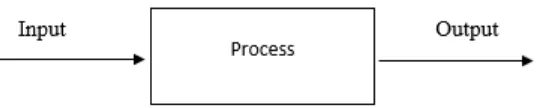
[image:20.595.174.442.258.312.2]
Figure 2.1: Process that be controlled
The term input that is appeared in Figure 2.1 is the jolt, excitation or charge connected to a control framework, normally from an outer vitality source, more often in order to produce a predetermined reaction from the control framework, though, the term of output is the real reaction acquired from a control framework and it could possibly be same or equivalent to the predefined reaction inferred by the input. (Distefano et al.1990)
7
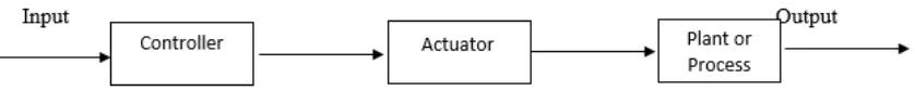
[image:21.595.97.516.291.333.2]The open loop control framework additionally called as linear control framework or non-feedback control framework. This open loop control framework will process its input to a framework utilizing a specific estimation of set point from the input and its model of the framework. The characteristic for the open loop controller is that it does not feedback to figure out whether its input has accomplish the wanted objective. This implies the framework does not watch the output of the processes that it is controlling. Figure 2.2 show the basic of the open loop control system.
Figure 2.2: Example of open loop control system
(Dorf and Bishop.2008)
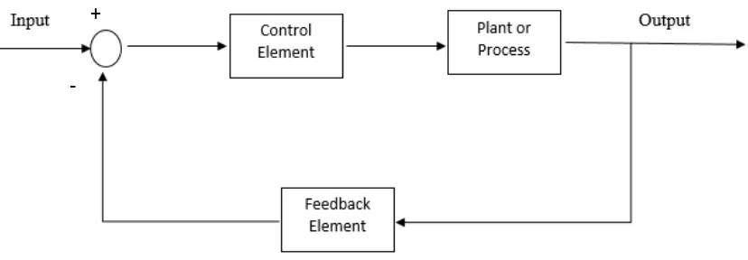
Closed loop control system is an opposite of an open loop control system. This closed loop control system also called as a feedback signal. A feedback control framework is a control framework that has a tendency to keep up a recommended relationship of one framework variable to another by looking at the capacity of these factors and utilizing the distinction as a method for control. (Dorf and Bishop.2008)
8
Figure 2.3: Example of closed loop control system with feedback
(Distefano et al.1990)
By implementing the closed loop control system, the system has many advantages despite of the cost and complexity of the system increases. The following advantages of closed loop control system are the diminished affectability of the framework to variation in the parameter of the process and enhanced dismissal of the unsettling influences. Besides that, the closed loop control system will give an improved in measurement noise attenuation and enhanced in diminishment steady state error of the framework. And lastly, the simple in control and adjustment of transient reaction of the framework can be gotten while actualizing the closed loop control framework. (Dorf and Bishop.2008)
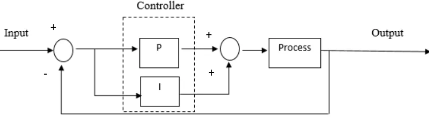
2.2.1 Proportional Integral Controller (PI)
The proportional integral controller is commonly used to eliminate the steady state error, but small integral is mostly used to avoid the closed loop system become destabilizing. In various systems Ki is in charge of driving the error to zero. Be that as it may, when the Ki
is set too high it may cause oscillation or instability or integrator windup or actuator immersion. As term of speed and general strength of the framework, it has a negative effect. Since the PI controller has no ability to foresee the future error of the framework, it can't diminish the rise time and take out the oscillation. (Temel et al. 2013)
9
[image:23.595.102.525.258.374.2]The PI controller is unquestionably the most commonly used control algorithms. This controller has traditionally been tuned empirically by the method that described in Ziegler and Nicholas. The method that is described by Ziegler and Nicholas has a great advantage of requiring very little information about the process. However, a significant disadvantage because the method, inherently gives a very poor damping, typically
ζ≈
0.2Figure 2.4: Example of simple PI controller
Based on the Figure 2.4, the proportional controller is set parallel with the integral controller. There are a few reasons to search for better techniques in designing the PI controllers. One reason is the noteworthy effect it might give on because of the spreading utilization of the controllers and another reason is that developing auto-tuners and tuning devices can benefit significantly from enhanced outline techniques. However, there are required to have an efficient design method. One of the prerequisite is, it ought to be applicable to an extensive variety of frameworks and it ought to have the likelihood to present details that catch the pith of real control issues. The technique ought to be vigorous as in it gives controller parameters if they exist, or if the determinations can't be met a fitting appropriate diagnosis ought to be displayed.(ÅStrÖM et al. 1998)
According to Wang et al. (2014), PI controller for auto tuning is really demanding in this current situation, without knowing the varying the operating parameters. A technique that is very powerful in solves problem in designing the PI controller. The technique is used
+
+
10
based on an adaptive estimation algorithm. In (Santra et al. 2016) mention that the PI controller is one of the controller that is commonly used controller in industrial automation. Due to the functional simplicity of the PI controller compared to the conventional control make the PI controller is more attractive and the advantages rather than conventional controllers and also successful applications in industry. Besides that, a controller without integral action in a feedback control system may make the steady state error of external disturbance and set-point adjustment, these actions is one of the proportional feedback control law. Hence, they obtain a robust feedback in time varying input delay with a delay-dependent sampled data of PI law and which ensures the asymptotic stabilization for the uncertain time delay. Direct and local feedback measurement are required by PI controller, thus it’s suitable for industrial applications.
According to He and Liu (2011), single-input and single-output (SISO) system are applied in most PI controller. These because most of the control scheme of traditional PI controller is a frequency-based domain. Withal, in engineering multiple-input and output (MIMO) always in PI controller. To solve the constrained tracking system problem, a generalized PI control strategy in discrete-time context is applied especially for stochastic systems. In the study, there are some cases that some of system states are not measurable when the feedback of the PI controller is failing to achieve the stability. In the industrial control process, the applications of PI control method is comprehensively be implemented. Also in the study, to get stabilize the uncertain Markovian Jumping System (MJSs), the PI controller is needed to design effectively.