SPEED CONTROL OF BLDC MOTOR USING PID CONTROLLER
AND FUZZY PID CONTROLLER
Mr.K Trinadh Babu1, Ms.Sri Lakshmi Davuluri2
1. INTRODUCTION
For as long as two decades a few Asian nations, for example, Japan, which have been under weight from high energy costs, have actualized variable pace PM motor drives for energy sparing applications, for example, aeration and cooling systems and iceboxes [1]. Then again, the U.S.A. has continued utilizing modest actuation motor drives, which have around 10% lower productivity than customizable PM motor drives for energy sparing applications. Hence as of late, the expansion in energy costs goads higher requests of variable rate PM motor drives. Likewise, late fast multiplication of motor crashes into the car business, in view of half and half drives, produces a genuine interest for high effective PM motor drives, and this was the start of enthusiasm for BLDC motors. BLDC motors, additionally called Permanent Magnet DC Synchronous motors, are one of the motor sorts that have all the more quickly picked up prominence, basically as a result of their better attributes and execution [2]. These motors are utilized as a part of an incredible measure of mechanical segments on the grounds that their engineering is appropriate for any wellbeing basic applications. The brushless DC motor is a synchronous electric motor that, from a demonstrating point of view, looks precisely like a DC motor, having a straight relationship amongst current and torque, voltage and rpm. It is an electronically controlled replacement framework, rather than having a mechanical compensation, which is commonplace of brushed motors. Also, the electromagnets don't move, the perpetual magnets pivot and the armature stays static. This gets around the issue of how to exchange current to a moving armature. With a specific end goal to do this, the brush-framework/commutator gathering is supplanted by an astute electronic controller, which plays out the same force dispersion as a brushed DC motor [3]. BLDC motors have numerous focal points over brushed DC motors and prompting motors, for example, a superior velocity versus torque qualities, high element reaction, high effectiveness and unwavering quality, long working life (no brush disintegration), silent operation, higher pace reaches and lessening of electromagnetic obstruction (EMI). In the investigation, the motor pace is kept steady and the heap is differing from zero to top torque. The motor pace holding steady under fluctuating burden condition is an alluring way to deal with control the motor under shifting burden condition. By utilizing this methodology, PID controller is utilized in this framework to beat the undesirable undershoot of motor velocity because of fluctuating burden sway at certain strange conditions. The proposed framework model utilizing PID control plan, is composed on Mat lab and reenactments performed on Simulink stage. In this paper, the pace control procedure of independently energized DC motor under differing load condition is given reenactments. The DC motor model is produced and Mat lab recreation has been done under exasperating burden conditions on Simulink stage. Fuzzy PID controller is utilized in this control framework keeping in mind the end goal to get craved reaction of the framework. The operation and tuning principles of fuzzy PID controller, PID controller is likewise talked about. Toward the end, test result is exhibited and talked about.
1 M,E,Asst Professor, Department of Electrical and Electronics Engineering, Anil Neerukonda Institute of Technology
&Sciences, Visakhapatnam, Andhra Pradesh, India
2 M.E,Asst Professor, Department of Electrical and Electronics Engineering, Anil Neerukonda Institute of Technology &
Sciences, Visakhapatnam, Andhra Pradesh, India
Abstract: BLDC motors are extremely well known and are supplanting brush less motors in various applications. Since the BLDC motor does not require commutator and because of its predominant electrical and mechanical attributes and its capacity to work in dangerous conditions it is more dependable than the DC motor. Generally likewise, drive conduct is measured with the assistance of Back Emf detecting. Since the BLDC motor does not require commutator and because of its prevalent electrical and mechanical qualities and its capacity to work in dangerous conditions it is more solid than the DC motor. Customarily, three-stage inverters are for the most part used to control these motors, requiring a rotor position sensor for beginning and for giving the best possible compensation arrangement to stator windings. The impediments of motor control framework are expanded cost and size of the motor, and need extraordinary mechanical plan for mounting the sensors with a specific end goal to control the BLDC motor, a Fuzzy PID controller is planned as the controller of the BLDC motor. The test results check that a Fuzzy PID controller has preferable control execution over the ordinary PID controller. The displaying, control and recreation of the BLDC motor have been done utilizing the product bundle MATLAB/SIMULINK.
Keywords – Fuzzy PID controller, BLDC motor drives, Speed Estimation, back-EMF. PID Controller
distinguished by position sensors. At the point when a BLDC motor pivots, every winding creates a voltage known as back Electromotive Force or back EMF, which contradicts the principle voltage supplied to the windings as indicated by Lenz's Law. The extremity of this back EMF is in inverse heading of the invigorated voltage. Back EMF depends basically on three components (an) Angular speed of the rotor, (b) Magnetic field produced by rotor magnets and (c) the quantity of turns in the stator windings
Figure.1: PM Brushless DC Motor waveforms
BLDC motors are a lower of the most usually utilized DC motor, the brushed DC motor, and they have the same torque and pace execution bend qualities. The significant distinction between the two is the utilization of brushes. BLDC motors don't have brushes (henceforth the name "brushless DC") and must be electronically commutated [5]. Replacement is the demonstration of changing the motor stage streams at the fitting times to deliver rotational torque .DC motors use mechanical commutators and brushes to accomplish the compensation .BLDC Motors use Hall Effect sensors set up of commutators. The stators of BLDC motors are the curls, and the rotors are the changeless magnets. The stators build up the attractive fields to make the rotor pivoting .The BLDC Motor works in numerous modes (stages), however the most well-known is the 3-phase.The 3-stage has better productivity and gives very low torque. The 3phase has a decent exactness in control .The qualities conditions of BLDC motors can be represented as:
���� (t) = L (1)
���� = ��.ω (t) (2)
T (t) =��. i (t) (3)
T(t) = J (4)
Figure.2: The block diagram of BLDC motor
The parameters of the motors used for simulation are as follows:
Table I PARAMETERS OF THE MOTOR PARAMETERS Values and units
R 21.2 Ω
�� 0.1433 Vs ���−1
D 1*10−4Kg-m s/ rad
L 0.052 H
�� 0.1433 Kg-m/A
J 1*10−5Kgm �2/rad
3. CIRCUIT DESCRIPTIONS AND OPERATION
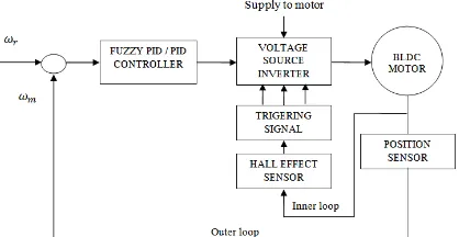
The complete block diagram of speed control of three phase BLDC Motor is below Fig. 3. Two control loops are used to control BLDC motor. The inner loop synchronizes the inverter gates signals with the electromotive forces. The outer loop controls the motor's speed by varying the DC bus voltage. Voltage Source Inverter circuit of BLDC Motor is shown below Fig. 4.
Figure.3: Block Diagram of Speed Control Of Brushless Dc Motor
.
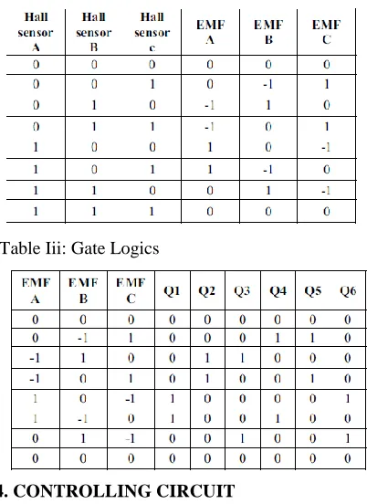
Table Iii: Gate Logics
4. CONTROLLING CIRCUIT
4.1. PID Controller
Consider the characteristics parameters – proportional (P), integral (I), and derivative (D) controls, as applied to the diagram below in Fig.5, the system,
Figure. 5: Simulation model of PID Controller
A PID controller is simple three-term controller. The letter P, I and D stand for P- Proportional, I- Integral, D- Derivative. The transfer function of the most basic form of PID controller, is
Where KP = Proportional gain, KI = Integral gain and KD = Derivative gain. The control u from the controller to the plant is equal to the Proportional gain (KP) times the magnitude of the error pluse the Integral gain (Ki) times the integral of the error
Due to its simplicity and excellent if not optimal performance in many applications, PID controllers are used in more than 95% of closed-loop industrial processes We are most interested in four major characteristics of the closed-loop step response. They are
Rise Time: the time it takes for the plant output Y to rise beyond 90% of the desired level for the first time. Overshoot: how much the peak level is higher than the steady state, normalized against the steady state. Settling Time: the time it takes for the system to converge to its steady state.
Steady-state Error: the difference between the steady-state output and the desired output.
The Values of Kp, Ki and Kd values of PID Controller is shown in below table III are obtained by using the ZN method.
Tableiv:Pidvalues
4.2. Fuzzy PID Controller
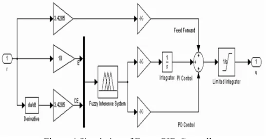
Fuzzy PID controller used in this paper is based on two inputs and one output. The overall structure of used controller is shown in Fig. 6. In Fuzzy PID controller only one output which are connected to Kp, Ki and Kd. Real interval of variables is obtained by using scaling factors which are Se, Sde and Su. The fuzzy control rule is in the form of: IF e=Ei and ce=dEj THAN UPD=UPD(i,j). These rules are written in a rule base look-up table which is shown in Fig. 8. The rule base structure is Mamdani type.
Figure 6:Simulation of Fuzzy PID Controller
FLC has two inputs and one output. These are error (e), error change (de) and control signal, respectively. A linguistic variable which implies inputs and output have been classified as: NB, NM, NS, Z, PS, PM, PB. Inputs and output are all normalized in the interval of [-3,3] as shown in Fig. 7.
Figure 7: Membership functions of output
6. CONCLUSION
A performance comparison of PID Controller and fuzzy PID controller has been carried out by several simulations. The results have shown that fuzzy PID controller regulator is better than conventional PID controller under variable operating conditions such as sudden variation in load conditions. The performance of FPIDC is excellent for reducing torque ripples. The conclusion is that fuzzy regulator is found to be more robust, stable flexible and insensitive to parameter variations as compared with conventional PID Controllers.
7. REFERENCES
[1]. H.Le-Huy, P.Perret, and R.Feuillet, “Minimization of torque ripple in brushless dc motor drives”, IEEE Trans.Ind.Appl., Vol. IA-22, no.4, pp.748-755, Jul./Aug.1986.
[2]. H.Zeroug, B.Boukais, and H.Sahraoui, “Analysis of Torque Ripple in a Brushless DC Motor”, IEEE Transs on magnetics, Vol.38, No.2, March 2002. [3]. Haifeng Lu, Lei Zhang and Wenlong Qu “A New Torque Control Method for Torque Ripple Minimization of BLDC motors with unideal back EMF” –
IEEE Transaction on power electronics, Vol., 23, No.2, March 2008
[4]. Wei Chen and Changliang Xia, “Sensorless Control of Brushless DC Motor Based on Fuzzy Logic”, Trans.Ind.Appl, 2006