Abstract: In electric vehicle segment it is significantly observed that the excess weight of batteries (>10% of overall weight) reduces the travel range of electric vehicle. This excess weight of the batteries causes higher compression of the springs & also reduce the space available for suspension travel which reduces the life of suspension & comfort to the passenger. To overcome these issues, suspension needs to be reconfigured in terms of geometry & material of the suspension. Considering above changes in suspension system, Leaf Spring can be considered due to its proven history. Leaf spring has high load bearing capacity & can handle high loads at less deflection resulting in smoother ride. In this study glass fiber is used to analyze the application of leaf spring for excess weight in electric vehicle. The main objective of this study is to investigate feasibility of composite material for leaf spring to withstand the excess load in Electric vehicle. Rear leaf spring of TATA Sumo passenger vehicle is considered as case study model, which is semi-elliptical laminated type. The CAD model was created in CATIA & imported to ANSYS. Analytical, Experimental and Finite Element Analysis were carried out on composite prototype. Weight optimization of 67.70% for GFRP is observed in comparison to EN 46 material. For deflection 3.93%, for stiffness 4.06%, for energy absorbed 3.94% and for natural frequency is 5.25% difference is observed.
Index Terms: Composite Material; Electric Vehicle (EV); Finite Element Analysis; Glass Fiber Reinforced Plastic (GFRP); Leaf Spring; Prototype Testing.
I. INTRODUCTION
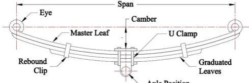
Leaf spring is one of the earliest and proven type of suspension system, which were called as carriage springs. Leaf spring is a straightforward spring that is widely used for wheeled vehicle suspension. Leaf springs are also used to regulate the height the car, which helps maintain the wheels on the highway aligned. The construction of leaf spring is very simple and mechanically strong as it supports frame and axle of the vehicle. Damping of the axle can be controlled by means of proper designing, positioning and installation of leaf spring in vehicle. The rosling of vehicle is avoided by installing the leaf springs wider from each other. Due to its advantages, leaf springs are widely used in many applications. The constructional arrangement of simple conventional semi elliptical leaf spring for basic parameters of design are as shown in fig. 1.
Revised Manuscript Received on July 09, 2019
s Mayur D. Teli, M. Tech – Mechanical Engineering, Vishwakarma Institute of Technology (VIT), Pune, INDIA.
Umesh S. Chavan, Mechanical Engineering, Vishwakarma Institute of Technology (VIT), Pune, INDIA.
[image:1.595.303.548.209.291.2]Haribhau G. Phakatkar, Mechanical Engineering, Trinity College of Engineering, Pune, INDIA.
Fig. 1: Semi-elliptical laminated leaf spring Leaf spring used for medium and heavy vehicles consists off several leaves assembled together with linearly larger leaves one above other stacked together. As leaf spring is manufactured from solid metal plates layered together, they give huge amount of support in between frame, axle and wheels of vehicle. Leaf spring can be directly connected to the frame at both ends or in general case one end is directly connected to frame and other end is connected through a shackle which gives swinging motion. Leaf spring is an assembly of rectangular cross sectioned metal plates with reducing length in the shape of an arc aligned one on another and stacked with the help of clips. The ends of plates are shaped in the form of round circle called as eye of the leaf spring. The leaf with maximum length is known as master leaf and others as graduated leaf. The vertical length between center of eye and master leaf is known as free camber which plays an important role in this suspension system.
Leaf spring can be classified into following basic types. A. Mono or single leaf spring
B. Multi leaf or laminated leaf spring
The traditional semi elliptical leaf spring of case study model TATA Sumo Gold can be observed in below figure. This leaf spring is obtained from local automobile market and used as a reference for further investigation process. The leaf spring itself is used as pattern to obtain desired dimensions from the composite prototype to attain maximum accuracy in validation of this study.
Fig. 2: TATA Sumo semi-elliptical leaf spring
Design, Analysis and Experimental Testing of
Composite Leaf Spring for Application in
Electric Vehicle
II. PROBLEMSTATEMENT
[image:2.595.47.291.494.597.2]In order to fulfil the precise travel range of electric vehicle, they must be lighter and more mass-efficient. The main factor affecting the range of travel for electric vehicle is weight of the batteries. To prove this statement, we consider an example of two similar automobile models from same manufacturer with exact specifications. From fig. 3 it is observed that left side vehicle runs on IC engine whereas right-side vehicle runs on pure electricity. The difference between basic curb weight or unladden weight of two vehicles is approximately 10% of overall vehicle weight. In IC engine this weight will be absent, but in electric vehicle this weight will be present all time. The excess weight in electric vehicle causes more compression of spring for every cycle, resulting in reduced load bearing capacity, lower ground clearance, lower ride comfort due to suspension movement.
Fig. 3: Weight difference between ICE and Electric vehicle of same model.
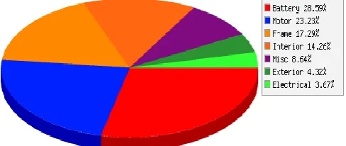
Cost of restoring or configuring the conventional coil spring is high. As the modification made in coil spring tends to change the stiffness of the spring material which is crucial parameter in case of suspension system for human ride comfort. New coil spring is to be selected which will cost on higher side so turning towards economical option leaf spring is considered which satisfies above conditions with high load bearing capacity, provides support between axle and suspension, handle high loads at less deflection which provide smooth ride. Market analysis of weight distribution in tesla electric vehicles as shown in below graph 1:
Graph 1: Weight distribution in electric vehicles. [1] As observed from graph 1, the frame occupies 17.29% of the overall weight of vehicle, which also considers suspension system. In addition to this leaf spring occupies most of the weight as it is manufactured from solid steel plates.
Glass Fiber Reinforced Plastic are good alternative for conventional spring grade steel [3]. Glass fiber reinforced plastic composite material have density of 2610 kg/m3 compared to 8080 kg/m3 of EN46, hence there will be vast weight difference between composite and steel leaf spring.
The case study model selected for this investigation is TATA Sumo passenger vehicle. Due to easy of availability and construction of leaf spring this model is selected. The rear suspension of this model contains traditional semi-elliptical laminated leaf spring.
III. OBJECTIVE
1.Perform chemical test on case study leaf spring to identify the conventional material according to BS 970:1991 standard.
2.Analytical analysis of conventional leaf spring for normal and worst conditions according to SAE HS 788 standard. 3.Prototype parameter finalization based on design and
analytical analysis of conventional and GFRP leaf spring. 4.GFRP prototype manufacturing according to parameters
from analytical analysis.
5.Perform compression test on GFRP prototype to obtain deflection, stiffness and energy absorbed according to ¬ASTM D790 standard.
6.Perform vibration test on GFRP prototype to obtain the natural frequency according to ISO 2631.
7.Finite element analysis of GFRP prototype.
8.Feasibility study of GFRP leaf spring in static conditions.
IV. LITERATUREREVIEW
Kale Dipak and Dr. Rachaiyya Arakerimath have evaluated design of composite leaf spring from which they conclude: Weight reduction and strength improvement of automotive components is research demand nowadays. The prediction of approximate fatigue life is carried in this paper for leaf spring used in automobile vehicle with composite material by simulation approach and then finite element analysis for validation for calculation mentioned. Composite components fulfil this need adequately. Composite components fulfil this need adequately. This paper is concentrated on same principal for leaf spring of automobile. E-glass with epoxy resin composite material is used for analysis and experimentation. Prototype is manufactured by hand lay-up method. Permissible fatigue life of 221160 cycles is achieved. The case-study model for this research is TATA Sumo Grande version, which has semi-elliptical leaf spring in rear suspension. Design is based on static conditions and obtained safe for static application. [2]
Santosh Patel and Utkarsh Mansore have performed parametric design and comparative analysis of multi leaf spring for light automotive vehicle. In this paper epoxy resin, carbon fibre reinforced plastic and glass fibre reinforced plastic are composite materials used in place of steel grade multi leaf spring. For static load, deflection in epoxy resin is higher than steel spring. It is found that epoxy resin, CFRP and GFRP are excellent replaceable material for steel leaf spring. [3]
Wu Ren, Bo Peng, Jiefen Shen, Yang Li and Yi Yu have researched study on vibration characteristics and human riding comfort of a special equipment cab. This paper is based on people-oriented concept in which reduction of long term physical and mental health damage of operator a hammer test is performed on special equipment cab for flat road. As per conclusion first three natural frequencies obtained are 7 Hz, 7.8 Hz and 12 Hz which are closed to vibration sensitivity of human body. The natural frequency should be reduced to improve the driver comfort. Far the vehicle and cab natural frequencies more comfort to
Basavraj Kabanur and Prof. P. S. Patil have completed paper on improve the design of leaf spring by reducing the frictional stress. This paper concludes that increase in strain energy improved the ride comfort of vehicle. The modal behaviour of leaf spring can be observed based on natural frequency and mode shapes of leaf spring. Each mode shape of composite leaf spring gives deflection in different axes. From this mode shapes composite leaf spring can be studied for resonance frequencies and in which axis the leaf spring is going to deflect for its first natural frequency. [5]
Wen-ku Shi, Cheng Liu, Zhi-yong Chen, Wei He and Qing-hua Zu have completed efficient method for calculating the composite stiffness of parabolic leaf springs with variable stiffness for vehicle rear suspension. The composite leaf spring with parabolic parameters were studied in this investigation. As per conclusion, equation is obtained to calculate the composite stiffness of multileaf springs in full contact with the primary and auxiliary springs. The rig test and simulation verify the calculation technique. Design parameters are addressed for development of leaf spring. [6]
Dasari Kumar and Abdul Kalam SD have studied design, analysis and comparison between the conventional materials with composite material of the leaf springs. In this paper e-glass epoxy composite and steel leaf spring is used for design and analysis. By implementing E-glass epoxy composite material for multi leaf spring a significant 69.48% of weight reduction is observed. In fea of leaf spring the first natural frequency obtained is 18.547 Hz lower than the irregularities from road condition of maximum frequency 12 Hz. Therefore, design considerations are safe. [7]
Harshit, Sanjiv Kumar and Antariksha Verma have performed design and simulation of leaf spring for TATA-ACE mini loader truck using fem. The composite leaf spring for TATA ACE commercial mini loader truck in analytical and simulation approach is studied in this paper. As per conclusion, the composite leaf spring is lighter and economical compared to steel leaf spring considering same design specifications. E-glass epoxy material is good compared to carbon epoxy and Kevlar epoxy based on analysis. Fatigue life of e-glass epoxy composite leaf spring is observed higher than steel leaf spring according to total life approach. [8]
Pramod Shinde, Piyush Talekar, Yogesh Kamble and Sandip Desai completed vibration analysis of composite leaf spring used for passenger car. As per experimentation from this paper, observed natural frequency values for composite material is higher than steel due to which vibration is low in composite leaf spring which provide higher comfort ride. Directional stability is gained by reducing the weight of leaf spring due to application of composite material. [9]
Putti Srinivasa Rao and Revu Venkatesh performed modal and harmonic analysis of leaf spring using composite materials. This study is based on modal and harmonic analysis based on fea and theoretical method. Natural frequencies are obtained from ansys fft spectrum, in which specimens are addressed as frequency corresponding to peaks present in fft. The output screen of fft analyzer displays the graph of force vs frequency from original time domain signal. Kevlar has high resonance point and high weight saving tendency. [10]
S. Karditsas, G. Karditsas, A. Mihailidis, A. Savaidis and R. Fragoudakis have completed design, calculation and testing requirements of leaf spring. They have concluded that the design criteria consider vertical loads from straight driving and biaxial loads from full braking of vehicle. From experimentation S-N curve was prepared from six 4-point fatigue bending test from two load levels. [11]
Ajay B. K., Mandar Gophane and P. Baskar performed design and analysis of leaf spring with different arrangements of composite leaves with steel leaves. A 3D model is prepared. From their conclusion it is observed that alternate arrangement of composite leaves gives same strength of steel leaves. The composite material arrangement attains better weight reduction and also factor of safety is 4.1 compared to steel factor of safety which is 4.5. [12]
Nisar Shaikh and Prof. S. M. Rajmane have completed modelling and analysis of suspension system of TATA SUMO by using composite material under the static load condition by using fea. The composite leaf spring is studied for analytical and finite element analysis and validated for same. This paper concludes that deflection observed in composite leaf spring is higher than that of steel leaf spring by 9.27%. Which makes the composite spring softer and smoothens the ride quality. The composite leaf spring is able t resist static and fatigue load. Also, the straight-line relationship is observed in load vs stress graph. [13]
Ashish Borhade and Prof. Dr. J. T. Pattiwar have performed dynamic analysis of steel leaf spring. The values obtained from experimental analysis and fea are within same range. Hence this study with values of frequencies of selected steel leaf spring are correct values. Keeping the dimensional parameters of leaf spring common and changing the material, the difference in natural frequencies of these materials can be studied. Which is advantageous for material optimization in leaf spring. [14]
Vinkel Arora, Gian Bhushan and M. L. Aggarwal researched fatigue life assessment of 65Si7 leaf spring. In this research the fatigue life is determined by experimental, analytical and graphical method. The conclusions made were, the leaf spring will withstand around 15 to 17% higher than fatigue life predicted by SAE spring design manual approach. There is around 8 to 9% error in graphical and analytical methods of fatigue life prediction which are also time consuming. Ansys predicts fatigue life of leaf spring around 2 to 5% compared to experimental and analytical approach. [15]
Ranjeet Mithari, Amar Patil and Prof. E. N. Aitavade carried out analysis of composite leaf spring by using analytical and fea. Here analytical calculations from composite leaf spring are analysed with approach of simulation and then used for comparison for validation of design. Large weight difference of 84.4% is observed between steel and composite leaf spring. Higher vibration absorbing capacity is observed in composite leaf spring. Composite leaf spring have higher tendency of corrosion resistance. Hence it will work better in environmental conditions than that of steel
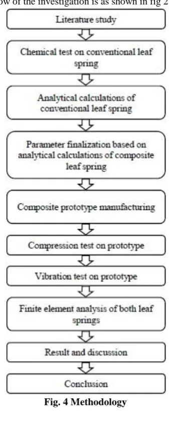
V. METHODOLOGY
[image:4.595.309.544.51.167.2]The flow of the investigation is as shown in fig 2 below:
Fig. 4 Methodology VI. CHEMICAL TESTING
[image:4.595.83.253.73.493.2]Chemical analysis of case study leaf spring was performed based on spark optical emission spectroscopy. This test is carried on conventional material for identifying the material grade and properties. In spark emission spectroscopy, the surface of material is grinded where spark is generated. The depth of grinding is dependent on type of material hardening on sample material. From rays emitted from spark, material grade is identified. Report of chemical analysis for conventional leaf spring is as listed in table 1:
TABLE I. Chemical Analysis Element Observed
%
Specified
Min Max
C % 0.40 0.35 0.45
Mn % 0.81 0.70 1.00
Si % 1.95 1.50 2.00
S % 0.031 --- 0.050
P % 0.018 --- 0.050
V % 0.010 --- 0.15
Remark-Chemical report of sample material tested as above meet with requirement of BS 970:1991 Grade EN 46
VII. ANALYTICALCALCULATIONS
Fig. 5 Free Body Diagram of semi elliptical leaf spring
A. Assumptions:
1.Leaf spring is a simply supported beam
2.Consider beam end conditions as hinged – hinged 3.Leaf spring has uniform cross section
4.Leaf spring possesses symmetry
5.Bending occurs due to application of force applied at the center of C/S
6.Leaf spring is under pure static load. B. EN 46 Leaf Spring
TABLE II. Case Study Model Specification
Particulars Value
Make & Model Tata Sumo Gold
Engine 2956 cc
Max Power 62.52 kW, 85PS@3000 rpm
Max Torque 250 Nm @1000 – 2000 rpm
Rear Suspension Leaf springs and antiroll bar
L x W x H (mm) 4258 x 1700 x 1925
Kerb Weight (wk) 1940 Kg
Gross Weight(wg) 2625 Kg
TABLE III. Leaf Spring Dimensions Parameter Value Unit Notation
Total length of leaf 975 mm 2L
No. of full-length leaves 2 unit nf
No. of graduated leaves 1 unit ng
Total number of leaves 3 unit n
Thickness of leaf 10 mm t
Width of leaf 70 mm w
Inside diameter of eye 18 mm d
Camber of leaf spring 140 mm y
Distance bet. U Bolt 110 mm l
Radius of curvature 1368 mm R
TABLE IV. EN 46 Material Properties
Parameter Value Unit Notation
Ultimate Tensile Strength
666.03 MPa Sut
Yield Tensile Strength
416.44 Mpa Syt
Young’s Modulus
183.40 Gpa E
Poisson’s Ratio 0.3 - µ
Density 8080 Kg/mm3 ρ
Note – Sut, Syt & E values are observed from specimen testing. µ, ρ and Hardness
[image:4.595.50.287.628.749.2]A.Design Calculation for EN 46 Leaf Spring:
a) Minimum and Maximum Load Conditions: [18]
Note:
1.Minimum load on all four suspension is 1940 Kg 2.Maximum load is 2625 Kg on all suspension 3.Excess 10% load is 2887.5 Kg on all suspensions.
1. Load acting on leaf spring (W): Minimum load acting on
leaf spring (Wmin):
Maximum load acting on leaf spring (Wmax):
N 2 9.81 4 k w min W
N 2 9.81 4 g w max W
Wmin = 2378.93 N Wmax = 3218.91 N
2. Effective length of leaf spring (L)
Span of leaf spring (Z): Effective length (L):
mm x 3 2 2L Z
mm 2 Z L
Z= 901.67 mm L = 450.83 mm
3. Deflection of spring (δ):
Minimum deflection of leaf spring (δmin):
mmf n 3 g n 2 3 t b E 3 L min W 12 min δ
δmin = 25.47 mm
Maximum deflection of leaf spring (δmax):
mmf n 3 g n 2 3 t b E 3 L max W 12 max δ
δmax = 34.46 mm
4. Bending Stress on Leaf Spring (σ): Minimum bending stress on leaf spring (σmin):
MPaf n 3 g n 2 2 t b L min W 18 min σ
σmin = 344.73 MPa
Maximum bending stress on leaf spring (σmax):
MPaf n 3 g n 2 2 t b L max W 18 max σ
σmax = 466.45 MPa
b) Worst load condition on leaf spring: [19]
Note:
1.Vehicle load on single suspension is 2625 Kg
1. Deflection of spring (δ):
o R 1 R 1 8 2 2Lδ …Ro is radius considered
negative δ = 173.72 mm
2. Bending Stress on Leaf Spring (σ):
2 δ SF 2Lt E 4
σ … SF is stiffening factor, For passenger car SF is 1.10 σ = 1474.66 MPa
A. Requirements of GFRP Leaf Spring:
1.Same case study model as of laminated leaf spring is considered.
2.The geometrical parameters such as length, width, camber, length between U bolt, no. of leaves and inside diameter of eye are fixed as required by model.
3.Thickness of leaf spring is free parameter which need to be calculated.
4.Maximum stress considered for design is 466.45 MPa. 5.Maximum deflection considered for design is 34.46 mm.
B. Design Calculation for GFRP Leaf Spring:
TABLE V. GFRP Material Properties
Parameter Value Unit Notation
Tensile Strength 900 Mpa Sut
Young’s Modulus 51 Gpa E
Density 2610 Kg/mm3 ρ
TABLE VI. Leaf Spring Thickness Calculation
Thickness (mm)
EN 46 GFRP
Maximum Load Excess Load (10%) Deflection (mm) Stress (MPa) Deflection (mm) Stress (MPa)
10 34.46 466.45 136.32 513.1
12 19.94 323.93 78.89 356.32
14 12.56 237.99 49.68 261.79
16 8.41 182.21 33.28 200.43
Remark:
1.For maximum load EN 46 leaf spring has deflection of 34.46 mm and stress of 466.45 MPa. GFRP should have values < mentioned.
2.For load considering excess 10% of battery weight, GFRP with 16 mm thickness has deflection of 33.28 mm and stress of 200.43 MPa.
3.As the values of GFRP are under mentioned values of EN 46 leaf spring, thickness selected for GFRP leaf spring is 16 mm.
TABLE VII. Calculation Values
Maximum load condition Worst load condition Deflection (mm) 33.28 Deflection (mm) 173.72
Stress (Mpa) 200.4
3
VIII. GFRPPROTOTYPEMANUFACTURING Composite leaf spring has same dimensions that of steel leaf spring except for the thickness, which is determined in analytical analysis. Composite leaf spring is manufactured by common hand lay-up method. Required materials for manufacturing are: leaf spring mold (wooden), release agent (polyvinyl alcohol PVA), mixing container (paper cups), mixing stick (pop stick), brush (nylon), roller (paint roller), scissors, epoxy (YD128), hardener (HY140), fiber (woven glass fiber sheet), vacuum bag with vacuum pump, gloves, lab coat, safety glasses.
Hand lay-up process in composite has some thumb rules to be followed which are evaluated in this process. In leaf spring prototype, thickness is free parameter and others are constrained. So, a wooden mold of same dimensions and determined thickness is made and prepared by cleaning and polishing the surface area. Then PVA release agent is applied on mold surface so that epoxy does not stick on it. Wait for certain time to set agent. The fiber sheet is cut into size of leaf spring when fully stretched. After preparation of all these materials, first step is to mix the epoxy with hardener in ratio of 2:1 with help of paper cups and pop sticks. Second step is to apply first epoxy coat on wooden surface with the help of brush and roller. Third step is to lay fiber layer on surface and with the help of roller it is softly wetted in epoxy layer. Then second and third step is continued until desired thickness is obtained. Finally, this setup is covered in a vacuum bag and vacuum pump is connected to it. The vacuum is created inside the bag which takes shape of surface and builds pressure which helps material to take shape of pattern and settle extra epoxy from the layers to one side. This process is cured at room temperature with time period of 24 hours. After curing the leaf is prepared for surface finishing such as cleaning with cloth, grinding with sand paper and finishing on buffing wheel. One single leaf spring is obtained by this process. Similarly, other two can be manufactured and assembled with the help of rebound clips.
Fig. 6 GFRP Leaf Spring Prototype IX. PROTOTYPETESTING A. Compression Test:
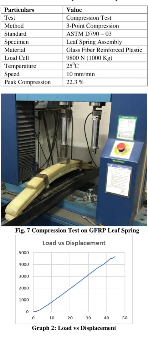
Compression test is one of the simple and fundamental test methods. In order to obtain values of deflection, stiffness and energy absorbed of GFRP composite leaf spring prototype experimentally, bend / compression test is carried out. Leaf spring is prepared for the test as per standard. For reinforced plastics 3-point compression test on universal testing machine is conducted with regulation of ASTM D790 standard. As per standard leaf spring is measured for its length end to end and then mounted on universal testing machine at the center in c channel as per the boundary conditions.
[image:6.595.308.545.189.737.2]Boundary conditions for test: both eye ends of GFRP leaf spring prototype are hinged supported i.e. rested on cylindrical support in a c-channel to guide the motion. As per the standard span length is measured and located centrally on UTM as shown in fig. 7. The load is applied gradually with constant speed and at room temperature. The load vs displacement graph is plotted autonomously as observed in graph 2. The load applied on GFRP leaf spring is more than the rated load of conventional leaf spring.
TABLE VIII. Compression Test Report
Particulars Value
Test Compression Test
Method 3-Point Compression
Standard ASTM D790 – 03
Specimen Leaf Spring Assembly
Material Glass Fiber Reinforced Plastic
Load Cell 9800 N (1000 Kg)
Temperature 250C
Speed 10 mm/min
Peak Compression 22.3 %
Fig. 7 Compression Test on GFRP Leaf Spring
B. Vibration Test:
[image:7.595.311.544.153.526.2]Vibration test is observed by introducing the external force to the object to be tested. Fast Fourier Transform FFT analyzer is used to convert the signal from original time domain to frequency domain. From this conversion the natural frequency of object can be observed and checked to avoid the resonance with system. The value of natural frequency is in compliance with ISO 2631. The test setup is as observed in fig. 8.
TABLE IX. Vibration Test Report
Particulars Value
Test Vibration (Natural Frequency)
Standard ISO 2631 (For Test Values)
Specimen Leaf Spring Assembly
Material Glass Fiber Reinforced Plastic
Temperature 250C
Sampling Mode 8 Channel
[image:7.595.51.288.182.436.2]First Natural Freq. 36.62 Hz
Fig. 8 FFT Analyzer Test Rig
The test process begins with fft spectrum with 8 channels out of which two are used, one for sensor to capture time domain signal and other for hammer to create minute impact on leaf spring. The composite leaf spring is mounted in between the two-bench vice with the help of cylindrical shaft support so as to create a hinged support boundary condition. The fft is connected to output screen via usb port and software is installed so as the signals from impact are visualized in real time. A small impact with the use of hammer is created and the vibrations are captured with help of sensor attached on leaf spring. This time domain signal is converted to frequency domain by fft spectrum and displayed on output screen in the form of force vs frequency graph. The first peak denotes the first natural frequency/mode shape of the leaf spring.
Fig. 9 FFT Output for GFRP Leaf Spring
X. FINITEELEMENTANALYSIS A. Modelling:
The dimensions of case study leaf spring are measured with help of Vernier caliper and measuring tape. A rough 2D sketch is prepared and then with the help of these dimensions 3D model of leaf spring is prepared in CATIA V5. First the parts such as master and graduated leaves are created and then assembled in assembly module. For GFRP leaf spring the thickness is only parameter that is changed and all the assembly is updated autonomously in assembly module. Once the assembly is created it is saved in IGES format so import in finite element analysis.
[image:7.595.51.288.186.428.2]Fig. 10 Assembly Model of GFRP Leaf Spring TABLE X. Material Properties
Parameter Value Unit
Youngs modulus along X direction 51000 MPa Youngs modulus along Y direction 6530 MPa Youngs modulus along Z direction 6530 MPa
Tensile strength 900 MPa
Compressive strength 450 MPa
Poisson’s ratio 0.36 -
Density 2610 Kg/mm3
Flexural strength 1200 MPa
The material properties listed in table 10 are gathered from the material test carried out on the test sample from the manufacturer. Material were created in engineering data of ANSYS by utilizing the properties from table 10 for GFRP material then applied to leaf spring.
B. Meshing:
[image:7.595.312.544.220.369.2] [image:7.595.50.287.612.749.2]C. Boundary Conditions:
[image:8.595.307.546.74.267.2]Considering hinged support at both eye ends of leaf spring, independent coordinate systems are prepared and remote displacement is applied at respective ends with respective constraints as observed in yellow color area of fig. 12. Vertically downward force of MPa is applied at bottom of last graduated leaf as observed in red arrow at the bottom.
Fig. 12 Boundary Condition for GRPF Leaf Spring
[image:8.595.50.287.307.464.2]D. Post Process Results:
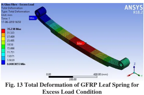
Fig. 13 Total Deformation of GFRP Leaf Spring for Excess Load Condition
The maximum deformation appears at the center of the leaf spring where the force is applied and minimum at the eye ends.
XI. RESULT AND DISCUSSION
The deflection values for GRPF leaf spring can be observed in graph 3.
Graph 3: Deflection Comparison for GFRP Leaf Spring
The stiffness values for GRPF leaf spring can be observed in graph 4.
Graph 4: Stiffness Comparison for GFRP Leaf Spring
The energy absorbed values for GRPF leaf spring can be observed in graph 5.
Graph 5: Energy Absorbed Comparison for GFRP Leaf Spring
The natural frequency values for GRPF leaf spring can be observed in graph 6.
The respective values of deflection, stiffness, energy absorbed and natural frequency in analytical calculation, experimental and finite element analysis are satisfactory.
The weight comparison for EN 46 and GRPF leaf spring can be observed in graph 6.
Graph 7: Weight Comparison for EN 46 and GFRP Leaf Spring
From above weight comparison graph, 67.70% weight difference between glass fiber reinforced plastic composite material and EN46 material is observed, which is highly weight saving and economical alternate for leaf spring in application of electric vehicle.
From this graph GFRP leaf spring can be considered for mass production.
The results observed by analytical calculations are used to obtain thickness parameter of GFRP leaf spring by implementing parametric analysis for GFRP leaf spring.
[image:9.595.50.288.116.295.2]The experimental test values and finite element analysis results are compared for validation of this study, which are listed as below in table 11:
TABLE XI. Excess Load Condition
Parameter Unit EXP FEA Error
Deflection mm 33.73 35.11 3.93
Stiffness N/mm 104.9 100.8 4.06
Energy absorbed kJ 59.71 62.16 3.94
Natural frequency Hz 36.63 38.66 5.25 From above table the values of deflection, stiffness, energy absorbed and natural frequency are obtained from finite element analysis and experimental testing on glass fiber leaf spring prototype, which has same specifications that of EN 46 leaf spring except for thickness parameter. The percentage error observed for validation between experimental testing and finite element analysis is between 3 to 6% range which is satisfactory value. The values observed in above table are in according to following standards:
1.Deflection- SAE HS 788 2.Stiffness - SAE HS 788 3.Natural frequency – ISO 2631.
XII. CONCLUSION
TATA Sumo leaf spring is considered in this study of feasibility analysis on GFRP leaf spring for application in electric vehicle.
The results observed during this analysis are within range with similar available existing results and governing standards. The following points can be concluded from the results observed during this study.
1.Chemical test performed on conventional leaf spring are as observed in table 1, which lists the elements present in material with observed and specified values. The element values from test meet with requirement of BS 970:1991 standard Grade EN 46.
2.Analytical calculations are performed for EN 46 leaf spring and through parametric analysis thickness parameter is confirmed for GFRP leaf spring. Rest all parameters are as it is.
3.GFRP leaf spring protype is manufactured using conventional hand layup method by following proper thumb rules.
4.Compression test is performed on GFRP leaf spring for observing values of deflection, stiffness and energy absorbed. 3-point compression method is used on UTM with compliance to ASTM D790-03 standard for reinforced composite material.
5.Vibration test is performed on GFRP leaf spring for observing values of natural frequency. FFT analyzer is used with compliance to ISO 2631 standard and graph for frequency domain is obtained.
6.Finite element analysis is performed on GFRP leaf spring. In static structural analysis system deflection of leaf spring under loading condition is observed and in modal analysis system natural frequency of leaf spring is observed. 7.Experimental and finite element analysis result are
compared for validation of this analysis. From table 11 it is observed that % difference in values for deflection 3.93%, for stiffness 4.06%, for energy absorbed 3.94% and for natural frequency is 5.25%, which are satisfactory values. 8.Weight difference between EN 46 leaf spring and GFRP
leaf spring is 67.70%.
9.From above points, it is found that Glass Fiber Reinforced Plastic (GFRP) leaf spring is better material and economical alternate instead of EN 46 for electric vehicle with excess battery weight for static conditions.
XIII. FUTURESCOPE
1.Dynamic analysis of GFRP leaf spring considering various loading conditions and road irregularities.
2.Fatigue analysis can be performed to estimate the life of the GFRP leaf spring.
ACKNOWLEDGMENT
I am very pleased to present the paper on “Design, Analysis & Testing of Composite Leaf Spring for Electric Vehicle”. I would like to mention a special thanks to my respected project guide Prof. (Dr.) Umesh Chavan Sir, who have given ongoing and enormous assistance at the individual level.
I am very happy to have worked under my project guide Prof. (Dr.) Umesh Chavan Sir.
REFERENCES
1. T. Network, “Tesla Model S Weight Distribution”, TESLARATI, 02-Jul-2014. [Online]. Available: https://www.teslarati.com/tesla-model-s-weight/.
2. K. Dipak and R. Arakerimath, “Design of Composite Leaf Spring”, International Journal of Technology and Science, Vol. 5, Issue 2, pp. 46-49, 2018.
3. S. Patel and U. Mansore, “Parametric Design and Comparative Analysis of Multi Leaf Spring for Light Automobile Vehicle”, International Research Journal of Engineering and Technology, Vol. 5, Issue 3, pp. 2467-2473, Mar 2018.
4. W. Ren, B. Peng, J. Shen, Y. Li and Y. Yu, “Study on Vibration Characteristics and Human Riding Comfort of a Social Equipment Cab”, Hindawi Journal of Sensors, Vol. 2018, pp. 1-8, Feb 2018. 5. B. Kabanur and Prof. P. S. Patil, “Improve the Design of Leaf Spring by
Reducing the Frictional Stress”, International Research Journal of Engineering and Technology, Vol. 4, Issue 8, pp. 1363-1370, Aug 2017. 6. W. Shi, C. Liu, Z. Chen, W. He and Q. Zu, “Efficient Method for Calculating the Composite Stiffness of Parabolic Leaf Springs with Variable Stiffness for Vehicle Rear Suspension”, Hindawi Mathematical Problems in Engineering, Vol. 2016, pp. 1-12, Feb 2016. 7. D. Kumar and A. Kalam, “Design, Analysis and Comparison between the Conventional Materials with Composite Materials of the Leaf Springs”, Fluid Mechanics Open Access, Vol. 3, Issue 1, pp. 1-20, 2016. 8. Harshit, S, Kumar and A. Verma, “Design and Simulation of Leaf Spring for TATA-ACE Mini Loader Truck using FEM”, International Journal of Interdisciplinary Research, Vol. 2, Issue 10, pp. 1421-1427, 2016.
9. P. Shinde, P. Talekar, Y. Kamble and S. Desai, “Vibration Analysis of Composite Leaf Spring used for Passenger Car”, International Conference on Recent Innovation in Engineering and Management, pp. 762-769, Mar 2016.
10. P. Rao and R. Venkatesh, “Modal and Harmonic Analysis of Leaf Spring using Composite Materials”, International Journal of Novel Research in Electrical and Mechanical Engineering, Vol. 2, Issue 3, pp. 67-75, Dec 2015.
11. S. Karditsas, G. Savaidis, A. Mihailidis, A. Savaidis and R. Fragoudakis, “Leaf Springs – Design, Calculation and Testing Requirements”, 35th International Symposium on Mechanics and Materials, pp. 1-11, June 2014.
12. K. Ajay, M. Gophane and P. Baskar, “Design and Analysis of Leaf Spring with Different Arrangements of Composite Leaves with Steel Leaves”, International Journal of Engineering Trends and Technology, Vol. 11, Issue 2, pp. 88-92, May 2014.
13. N. Shaikh and Prof. S. Rajmane, “Modelling and Analysis of Suspension System of TATA SUMO by using Composite Material under the Static Load Condition by using FEA”, International Journal of Engineering Trends and Technology, Vol. 12, Issue 2, pp. 64-73, Jun 2014.
14. A. Borhade and Prof. Dr. J. Pattiwar, “Dynamic Analysis of Steel Leaf Spring”, International Journal of Engineering Research and Technology, Vol. 3, Issue 11, pp. 306-310, Nov 2014.
15. V. Arora, G. Bhushan and M. Aggarwal, “Fatigue Life Assessment of 65Si7 Leaf Springs: A Comparative Study”, Hindawi International Scholarly Research Notices, Vol. 2014, pp. 1-11, 2014.
16. R. Mithari, A. Patil and Prof. E. Aitavade, “Analysis of Composite Leaf Spring by using Analytical and FEA”, International Journal of Engineering Science and Technology, Vol. 4, Issue 12, pp. 4809-4814, Dec 2012.
17. J. Woolman and R. Mottram, “The Mechanical and Physical Properties of British Standard En Steels (B.S. 970-1955)”, Steel User Service British Iron and Steel Research Association, Vol. 3, Issue 1, pp. 109-149, 1969.
18. R. Khurmi and J. Gupta, “Machine Design”, Eurasia Publishing House, Vol. 1, pp. 866-879, 2005.
19. SAE Spring Committee, “Spring Design Manual AE-11, HS 788”, SAE International (SAE), pp. 1.38-1.40, 1990.
AUTHORSPROFILE
Mayur D. Teli, M Tech.
Student, Mechanical Design Engineering Vishwakarma Institute of Technology, Pune Maharashtra, INDIA - 411037
Umesh S. Chavan, Ph. D. Professor, Mechanical Engineering Vishwakarma Institute of Technology, Pune Maharashtra, INDIA - 411037
Haribhau G. Phakatkar, Ph. D.