Abstract: The wind turbines have restriction on increasing its rotor diameter. Winglets are angled extensions or vertical projections at a wing's trail and are commonly utilized on commercial aircraft in combination with flat airfoils to minimize induced drag and increase lift. Introducing a winglet to the cutting edge of the turbine blade enhances the power generation without extending the intended rotor area. For the aeronautical industry and especially for high-performance sail planes, the winglet structure has been thoroughly examined. Because winglets have been shown to decrease drag and increase wind turbine rotor blade aerodynamic efficiency, it is major to realize and evaluate the method of performance and design enhancement used by previous researchers for this application. It provides a good description and concepts for handling the design process for the application of the wind turbine. The objective of the project is to evaluate turbine blade flow dynamics with winglet and to enhance the efficiency of its physical dimensions. CFD analysis would be go through by altering its physical size and shape with the target of realizing augmented power.
Keywords : Winglet, CFD analysis, Wind turbine blade.
I. INTRODUCTION
Alternative vitality sources are a significant subject for the use of a successful vitality asset later on since non-renewable energy sources are draining at quicker rate[1]. Moreover, the size of wind power use is still small in comparison to net energy demand; in particular, the level of technology in some remote areas is extremely small[2]. The projected rotor area is not increased by summing winglet to the turbine and it raises power generation[3].An increase in the efficiency of wind turbines would allow today's limits to be achieved.
A. Turbine Blades with Winglet
The aim of connecting a winglet to a blade of the windmill is to reduce the opposing force from the blades and thus increase the windmill's aerodynamic efficiency[4].
The geometry of a winglet is characterized by six parameters and it is illustrated in fig 1.
Height
Revised Manuscript Received on December 05, 2019.
Vijayakumar K , his/her department, Name of the affiliated College or University/Industry, City, Country. Email: [email protected]
Prabhu L, department, Name of the affiliated College or University/Industry, City, Country. Email: [email protected]
Ashraf Shaheen, department, Name of the affiliated College or University/Industry, City, Country. Email: [email protected]
[image:1.595.308.540.545.688.2] Twist angle Sweep angle Curvature radius Toe angle Cant angle
Fig. 1. Design parameters of winglet geometry
II. BASICSOFCOMPUTATIONALFLUID
DYNAMICS
A. Fluid Dynamics
Liquid elements is a subdiscipline of liquid mechanics that portrays the progression of liquids—fluids and gases. It has a few subdisciplines, including optimal design and hydrodynamics it.
B. Computational Fluid Dynamics
Computational fluid elements (CFD) are part of liquid mechanics that use mathematical analysis and data frameworks to analyze and take care of liquid stream issues
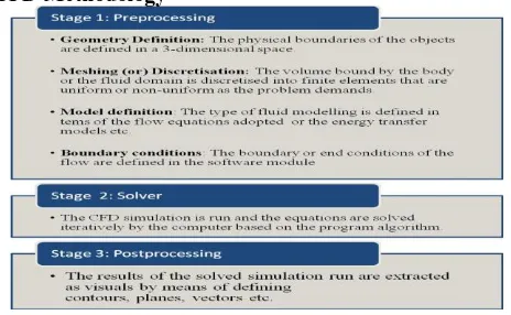
CFD Methodology
C. Types of Meshes
The method of producing an effective mesh is known as mesh generation. Specialized software programs for grid and mesh creation and
accessibility for a good package of technology and
Structure Optimization of Wind Turbine Blade
with Winglet using CFD
Structure Optimization of Wind Turbine Blade with Winglet using CFD
expertise have been developed to use this technology are essential for modelling efforts to be successful[5].
Since CFD has evolved, CFD analysts have been given better techniques and more computational power, resulting in various solver techniques. The expansion of acceptable mesh connectivity and mesh elements was one of the direct results of this development. The simplest network identification is based on a mesh connection or on the form of parts.
Classification
Since The most fundamental type of work characterization depends on the availability of the work: organized or unstructured[6].
Structured Meshes
An organized work is portrayed by customary availability that can be communicated as a few dimensional exhibits[7].
Unstructured Meshes
An unorganized mesh is defined by irregular routing that is not easily represented as a two or 3D, the space requirements for an informal mesh can be significantly greater as the data of the neighborhood must be specifically stored[8].
Hybrid Meshes
A mesh mix is a function comprising ordered pieces and unfocused partitionsparts[9].
[image:2.595.303.536.360.442.2]III. CFDTOOL–ANSYSCFX
Fig. 2. CFD Process
The process of CFD is shown in the figure 2.CFX consists of five computer modules connected by the sharing of
information required to conduct a CFD test. The basic modules of Ansys-CFX is shown in the figure 3.
Fig. 3. Basic Modules of Ansys-CFX
A. CFX-BUILD
Mainly it is used for Modeling and Meshing the geometry or domains. CFX-Build can use geometry information directly from MSC / PATRAN databases and other big CAD packs in addition to its own geometry software. Interfaces are
available for the following tools / format. It also supports IGES and ACIS formats.
IV. DEFINITIONOFPROBLEM
• Understanding the flow system around the blade of the wind turbine is essential to enhance its performance with winglet.
• CFD has been demonstrated to be powerful analyser for understanding and analyzing complex fluid flow problems.
• To analyse the flow characteristics of wind turbine blades without and with winglet
• To compare aerodynamic performance of wind turbine blade of varying winglet profiles with respect to the following parameters.
a) Height b)Cant angle
V. MATERIALSANDMETHODS
A. Modeling of Geometry
Demonstrating was finished utilizing Pro E software and sent out in IGES design. The design of wind turbine have been shown in the figure 4-5.
[image:2.595.81.260.394.542.2]PRO E Models of Wind Turbine
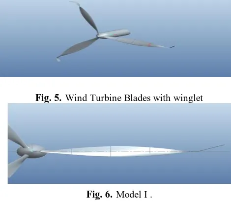
Fig. 4. Wind turbine blades wihtout winglet
Fig. 5. Wind Turbine Blades with winglet
Fig. 6. Model I .
[image:2.595.305.540.489.694.2] [image:2.595.64.274.615.707.2]Fig. 7. Model II .
Fig. 8. Model III .
Fig. 9. Model IV.
Parameters considered for analysis
Description
Cant angle Height of winglet
degrees m
Model 1 30 0.4
Model 2 70 0.4
Model 3 30 0.65
Model 4 70 0.65
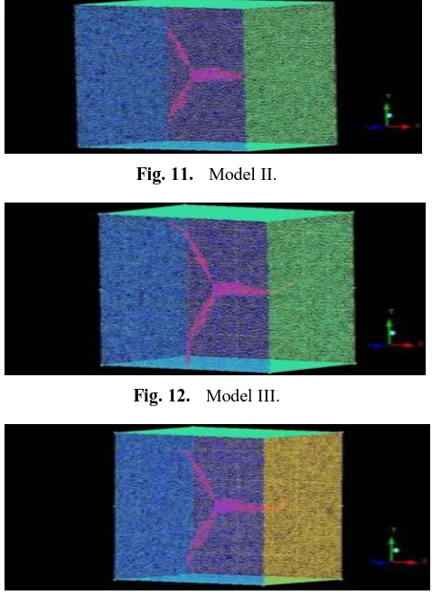
B. Meshing
The ideal is traded in IGES design and is utilized in ICEM-CFD apparatus.Model I,Model II,Model III and Model IV is shown in the figure 10-13.
Meshed Models of Wind Turbine
[image:3.595.54.287.49.379.2]
Fig. 10. Model I.
Fig. 11. Model II.
Fig. 12. Model III.
Fig. 13. Model IV.
Mesh element size
Element type : Tetrahedron Global Element Scale Factor : 2.3
C. CFX - Pre Processing
Boundary and Domain
Fluid Domain
Boundary Conditions
Boundary Type : Inlet Velocity : 5 m/s
Turbulence : Medium (Intensity=5%) Temperature : 30 C
Flow Direction : Normal to Boundary Condition
Outlet
Boundary Type : Outlet Pressure : 1 Atm
[image:3.595.312.551.52.381.2]Structure Optimization of Wind Turbine Blade with Winglet using CFD
[image:4.595.306.559.50.309.2]Fig. 14. Wind Turbine Blades without winglet
Fig. 15. Wind Turbine blades with winglet.
D. Solver Stage
After defining the pre request for simulation, models are imported into CFX — Solver Framework for sequential calculations and result file generation.
The CFX-Pre module for solver control parameters is shown below.
Control parameters
Residual Target : 1e-5
Time scale : Auto Time scale Number of sequence : 250
VI. RESULTSANDDISCUSSION
A. Velocity variation (Inlet Velocity = 5 m/s)
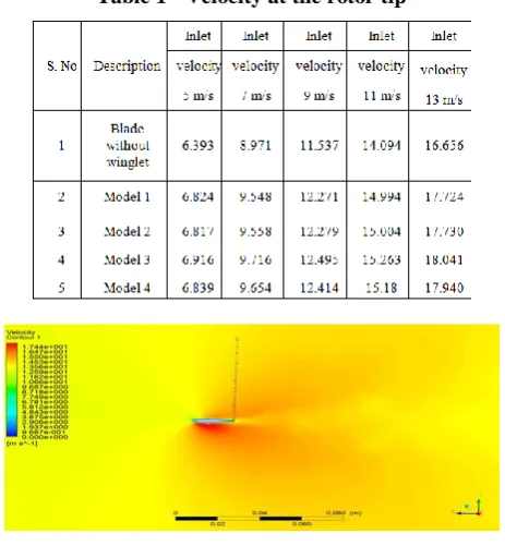
The figure 16-22 shows velocity variation across the wind turbine blades. The raise in velocity is observed at edge of the blade for all the designs. The blade without winglet exhibits relatively lower vortices than rest of the models. The strong vortices around the blade have been observed for model III and IV. The results show that the velocity relatively increases at the tip of turbine rotor of wind turbine having winglet and model III shows higher velocity. The higher the velocity at the rotor tip causes to increase the mass flow of air blades resulting in increased power generation.
Fig. 16. Wind Turbine Blades without winglet.
[image:4.595.304.557.61.589.2]Fig. 17. Model I
Fig. 18. Model II (with winglet)
[image:4.595.47.272.198.295.2]Fig. 19. Model III (with winglet)
Fig. 20. Model IV (with winglet).
B. Velocity variation (Inlet Velocity = 13 m/s)
The figure shows the velocity variation across the wind turbine blades for the inlet velocity of 13 m/s. The trend of increase in velocity has been observed around the tip of the blades. The vortices around the blades with winglet causes wake region causing in raised mass air flow. The models 3 and 4 exhibits increased velocity at the tip. The average increase in velocity of blades with winglet is 7.2% compared with without winglet for the
[image:4.595.314.560.327.626.2] [image:4.595.54.277.643.758.2]Fig. 21. Wind Turbine Blades without winglet.
C. Output Power and Velocity Variation
For different inlet velocities at the rotor tip is illustrated as follows.
[image:5.595.53.285.217.468.2]Table 1 - Velocity at the rotor tip
Fig. 22. Model III (with winglet).
D. Power Variation for Varying Velocity
[image:5.595.62.286.601.723.2]Figure 23 shows various models power output at wind turbine rotor. The power of output for blade with winglet is significantly high compared with blade without winglet. The variation in output power is marginal at lower velocities among the blade models. The power output is relatively higher for the model 3 when increasing the inlet velocity.
Fig. 23. The output power obtained at wind turbine rotor for various models.
VII. CONCLUSION
The analysis for wind turbine blade without and with winglets design was concluded and can be drawn. The
vortices around the blades with winglet causes wake region resulting in increased mass flow of air. The raise in velocity around the tip of blade with winglet is observed. The average raise in output power for blade with winglet is 23.28% compared with blade without winglet for the inlet velocity of 13 m/s. The variation in output power is marginal at lower velocities and it is relatively higher for the model 3 when increasing the inlet velocity.
REFERENCES
1. G A. Gupta, and R. S. Amano,” CFD analysis of wind turbine blade with winglets”, in International Design Engineering Technical Conferences and Computers and Information in Engineering Conference, Aug.2012,pp. 843-849.
2. E. Ferrer, and X. Munduate, “Wind turbine blade tip comparison using CFD”. In Journal of Physics: Conference Series ,Vol. 75, No. 1, 2007,pp. 012005.
3. M. A. Elfarra, “Horizontal axis wind turbine rotor blade: winglet and twist aerodynamic design and optimization using CFD”. Graduate School of Natural and Applied Sciences of Middle East Technical University, Phd, Thesis, Jan 2011.
4. J. Johansen ,NN. Sørensen , “ Aerodynamic investigation of winglets on wind turbine blades using CFD”,2006.
5. D. Gertz, D.A. Johnson, and N. Swytink-Binnema, “Comparative Measurements of the Effect of a Winglet on a Wind Turbine”. Wind Energy-Impact of Turbulence ,Springer, Berlin, Heidelberg, 2014,pp. 121-126.
6. N. Tobin ,A. Hamed ,L. Chamorro, “ An Experimental Study on the Effects of Winglets on the Wake and Performance of a Model Wind Turbine”. Energies. Vol.8,No.10,2015,pp.11955-72.
7. P. Saravanan ,KM. Parammasivam ,” Experimental investigation on small horizontal axis wind turbine rotor using winglets”,Journal of Applied Science and Engineering,Vol.16,No.2,Jun.2013,pp.159-64.
8. ANSYS Europe Ltd, ANSYS CFX solver modeling guide, V11,Technical
report, ANSYS Europe Ltd, 2007.
9. An Introduction to Computational Fluid Dynamics, The Finite Volume Method, H K Versteeg and W Malalasekera, 1995.
AUTHORSPROFILE
Vijayakumar K - Assistant Professor Department of Mechanical Engineering Aarupadai Veedu Institute of Technology Vinayaka Mission Research Foundation [email protected]
Prabhu L - Associate Professor Department of Mechanical Engineering Aarupadai Veedu Institute of Technology Vinayaka Mission Research Foundation
Ashraf Shaheen -UG Student Department of Mechanical Engineering Aarupadai Veedu Institute of Technology Vinayaka Mission Research Foundation
Sharan Prasad -UG Student Department of Mechanical Engineering Aarupadai Veedu Institute of Technology Vinayaka Mission Research Foundation
Akshay S -UG Student