White Rose Research Online
Universities of Leeds, Sheffield and York
http://eprints.whiterose.ac.uk/
This is a paper published in IEEE Transactions on Power Delivery.
White Rose Research Online URL for this paper:
http://eprints.whiterose.ac.uk/3620/
Published paper
Griffo, A. and Lauria, D. (2008)
Two-leg three-phase inverter control for
STATCOM and SSSC applications,
IEEE Transactions on Power Delivery,
Volume 23 (1), 361-370.
IEEE TRANSACTIONS ON POWER DELIVERY, VOL. 23, NO. 1, JANUARY 2008 361
Two-Leg Three-Phase Inverter Control for
STATCOM and SSSC Applications
Antonio Griffo and Davide Lauria
Abstract—Flexible ac transmission systems (FACTS) devices are attracting an increasing interest both in power system academic research and in electric utilities for their capabilities to improve steady-state performance as well as system stability. Several con-verter topologies for FACTS applications have been proposed in the recent literature, even if those based upon voltage source inverters (VSI) seem to be more attractive due to their intrinsic capability to rapidly respond to network changes such as perturbations subse-quent to a fault and their property of being immune to resonance problem. In this paper, a new topology for inverter-based FACTS is proposed. This configuration, employing a two-leg three-phase in-verter is employed for both series and parallel-connected reactive power compensators. The converter utilizes a modular topology for allowing a satisfaction of electronic components rating. A control strategy based on variable structure control technique with sliding mode is employed to track appropriate reference quantities. De-sign and control, as well as good tracking performances, are also verified through numerical simulations.
Index Terms—Flexible ac transmission systems, static syn-chronous compensator (STATCOM), static synsyn-chronous series compensator (SSSC), variable structure control.
I. INTRODUCTION
P
OWER system regulation has historically played a vital role for secure operation of electrical power systems. The interest towards the identification of the best control actions which could improve dynamic behaviour is further increased in modern power systems since the deregulation could involve stressed operating conditions. The evolution in power elec-tronic devices along with developments in control theory have allowed the design and implementation of structural controllers known as flexible ac transmission systems (FACTS), which are emerging as a viable technology for the improvement of power systems dynamic behavior. The benefits arising from FACTS devices are widely appreciated and are not restricted to the increase in power flows and stability margins [1]–[3], but also extend to power oscillations damping [4], [5].Many devices have been proposed in the past within the FACTS family, some of them based on thyristor switched reactors like the TCSC and StaticVar [6], while others, like the static compensator (STATCOM) [7], the static synchronous
se-Manuscript received August 8, 2006; revised December 14, 2006. Paper no. TPWRD-00469-2006.
A. Griffo is with the Department of Electronic and Electrical Engineering, University of Sheffield, Sheffield S1 3JD, U.K. (e-mail: [email protected]. uk).
D. Lauria is with the Department of Electrical Engineering, Università degli Studi di Napoli Federico II, 80125 Napoli, Italy (e-mail: davide.lauria@unina. it).
Digital Object Identifier 10.1109/TPWRD.2007.911132
ries compensator (SSSC) [8], the unified power flow controller (UPFC) [9], and the superconducting magnetic energy storage systems (SMES) [10], employ power electronic converters. This latter choice guarantees the best flexibility in control and rapidity of response. Several power converter topologies have been proposed for the implementation of FACTS devices, such as those based on voltage-source converters [11] and cur-rent-source converters [12]. Among voltage-source converters, line-frequency switching has been preferred to pulsewidth modulation (PWM) due to the past unavailability of high switching-frequency power devices with high power-handling capabilities. In order to achieve lower harmonic distortion, multipulse converter are employed, such as the 24- and 48-pulse converters [13]–[15]. Magnetic interfaces constituted by complex zig-zag phase shifting transformers are required for interfacing multipulse inverters with transmission network in order to counteract low order harmonics. With the use of multilevel converters [16], the necessity of complex coupling transformers could be avoided, at the expense of a greater com-plexity in control. Comprehensive circuit-level comparisons, along with advantages and drawbacks of several common arrangements for high-power converters, are presented in [11] and [17].
Several improvements in power semiconductor devices have been reported recently. Insulated gate-commutated thyristors (IGCTs) [18], [19] have been proposed and are already com-mercially available for high power operations with switching frequency in the kilohertz range. The emitter turn-off thyristor (ETO) promises to be a viable technology for very high power and high frequency PWM operation [20]–[22]. These pro-gresses are making PWM operation a competitive and effective alternative to line-frequency commutated control structure which are currently employed.
Power converters can be regarded as variable structure sys-tems due to their switching operation. Sliding-mode control for this type of system has gained widespread attention in the rel-evant literature due to its simplicity and intrinsic robustness against disturbances [23], [24]. Sliding-mode control is thus an effective alternative to classical PWM techniques, provided that sufficiently high switching-frequency devices are available. A viable solution to the problem of high frequency switching of high current levels is the employment of a number of parallel connected converters, controlled in such a way as to guarantee a balanced current sharing among them. In this paper, a converter based on the parallel connection of basic building blocks con-stituted by two-leg three-phase converter, for both parallel and series compensation, is described. This arrangement can pro-vide an alternative topology for STATCOM and SSSC devices.
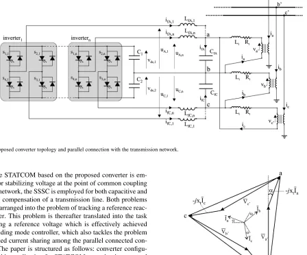
Fig. 1. Proposed converter topology and parallel connection with the transmission network.
While the STATCOM based on the proposed converter is em-ployed for stabilizing voltage at the point of common coupling with the network, the SSSC is employed for both capacitive and inductive compensation of a transmission line. Both problems can be rearranged into the problem of tracking a reference reac-tive power. This problem is thereafter translated into the task of tracking a reference voltage which is effectively achieved with a sliding mode controller, which also tackles the problem of balanced current sharing among the parallel connected con-verters. The paper is structured as follows: converter configu-ration and its application for STATCOM opeconfigu-ration is presented in Section II, along with mathematical derivations of both refer-ences quantities and control action. Series connection for SSSC operation is described in Section III. In Section IV, results of numerical simulations are reported, showing good tracking per-formances along with simplicity in design and control. The con-clusion is presented in Section V.
II. CONVERTERTOPOLOGY, STATCOMOPERATION,
ANDCONTROL
The topology of the proposed converter is illustrated in Fig. 1, as well as its shunt connection with the transmission network through a -Y transformer. The converter is constituted by the parallel connection of two-leg three-phase inverters. fil-ters are connected between each inverter output and the coupling transformer, in order to contribute to the smoothing of output voltages. The basic building block has been proposed as a com-ponent minimized topology for variable-speed induction motor drives [25], [26] and as a coupled rectifier/inverter system [27]. A three-level NPC variant has also been proposed for active fil-tering application [28].
Assuming a balanced three-phase operation, the converter output voltage is given by
[image:3.594.344.509.314.489.2](1)
Fig. 2. Phasor diagram illustrating STATCOM operation in capacitive compen-sation mode.
where is the transmission network phase p.u. voltage at the point of common coupling, is the STATCOM phase p.u. current and the coupling transformer leakage reactance. Leakage resistance has been neglected for the sake of simplicity. Voltages and can be derived analogously, and are equal to phase shifted by and rad, respectively, as il-lustrated by the phasor diagram in Fig. 2.
For the STATCOM to operate as a capacitive compensator, the currents drawn from the network should lead bus volt-ages by rad, while the currents should lag rad behind the voltages when inductive compensation is required. Assuming as a reference the phase of , the STATCOM refer-ence phase current is then
(2)
GRIFFO AND LAURIA: TWO-LEG THREE-PHASE INVERTER CONTROL FOR STATCOM AND SSSC APPLICATIONS 363
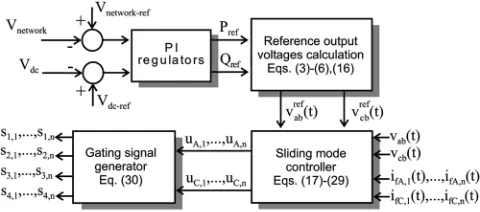
Fig. 3. Ac and dc control systems.
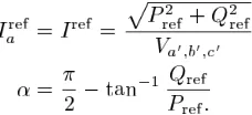
for losses in semiconductor devices and coupling transformer, thus maintaining dc voltage at a specified level. The magnitude of the reference current, as well as angle , can be derived by the reference values of active and reactive power as
(3)
(4)
Active and reactive power reference can either be fixed or dynamically adjusted as to regulate some network quantities. The most common STATCOM operation is voltage regulation at the point of common coupling. With this aim in mind, two simple PI regulators, as reported in Fig. 3, are adopted in the paper. The difference between network voltage magnitude and a reference is passed through a PI controller which determines the amount of reactive power compensation required. A regula-tion droop is usually present in practical arrangements and can be easily added. Another PI regulator maintains dc voltage at a specified level, by determining the amount of active power nec-essary for converter losses compensation. More complex con-trol schemes, which could further enhance system dynamic be-havior, are equally possible but, since the main focus is on the tracking capabilities of the proposed converter and control, only the simplest are presented.
Reference values for magnitude and phase of converter output voltage are then
(5)
(6)
and can be derived by phase shifting by and rad, respectively. In practical applications, a phase-locked loop (PLL) is necessary to synchronize with the network voltage.
Time-domain converter equations are presented in the fol-lowing.
A. Converter Equations
Voltages on ac filter capacitances which constitute the output to be regulated are described by
(7)
where
(8)
Equations for currents in filter inductances are
(9)
The control inputs to filters are given by
(10)
where for the k-th inverter
(11)
Currents in the primary of the coupling transformer are de-scribed by
(12)
Equations (7)–(12) can be easily rearranged in the state-space form as
(13)
where the state variables and the controllable and uncontrol-lable inputs , respectively, are given by
(14)
and the output is
(15)
Proper operation is achieved by regulating to their re-spective reference values given by
Fig. 4. Proposed control strategy for the converter in STATCOM operation.
by properly controlling acting on
switches gate signals . The
whole control strategy is illustrated in Fig. 4.
B. Variable Structure Control
Due to the switching action of power devices, power con-verters naturally belong to the class of variable structure sys-tems, whose structure changes according to some control law. Variable structure control (VSC) is a feedback control action widely employed for this kind of systems. VSC have been pro-posed for a variety of mechanical and electrical systems, also including power converters [29], power systems [30], and elec-trical drives [31]. The design of a VSC for a given system entails the choice of a switching control law with the aim of forcing system’s state trajectory towards a properly designed sliding surface in the state space, described by . Once the sliding surface is reached, the VS controller must preserve the motion of system’s trajectory on it, giving rise to the so-called sliding mode. Control objectives should be taken into account for an appropriate design of the sliding surface. In the present case, the goals of the controller can be itemized as follows.
1) Regulation of output voltages .
2) Balanced current sharing among parallel connected in-verters.
Keeping these aims in mind, the following sliding surface is proposed, utilizing the circular chain control strategy from [32]
(17)
where
(18)
with
The first two terms on the right-hand side of (18) account for output voltage regulation, while the third accounts for balanced current sharing among parallel connected converters. The derivative term is added recognizing that the relative degree
(i.e., the order of the derivative of the output required for the input to appear explicitly [23]) is two [33]. Once the sliding surface is hit at , the sliding mode occurs if and only if
(19)
The equivalent control given by:
(20)
assuming , describes an equivalent smooth feedback control that forces state trajectory of system (13) to stay on . Direct application of Proposition 1 in [34] to the present case demonstrates that a sliding mode exists if and only if each component of the equivalent control satisfies
(21)
This condition is fulfilled provided that voltages on dc capaci-tors are sufficiently high.
A reaching condition, sufficient for the trajectory of system’s state to reach the sliding surface is
(22)
Condition (22) guarantees that the time derivative of the quadratic function
(23)
is negative definite, thus (23) qualifies as a Lyapunov func-tion, demonstrating asymptotic stability of the state . In single-input control problem, actual control is derived as to ful-fill condition (22). Since system (13) is a multi-input system, actual controls would appear in a coupled manner in (23) thus making impossible to derive appropriate control actions. A linear time-invariant transformation:
(24)
with being a nonsingular matrix, chosen in order to trans-form the coupled multi-input control problem into decou-pled single input problems [24]. Motion on the sliding surface is not altered by transformation (24) since the equivalent control can be easily derived to be the same as (20). Furthermore, since is nonsingular, . The candidate Lyapunov function is now
(25)
whose time derivative is
(26)
If is chosen such that
GRIFFO AND LAURIA: TWO-LEG THREE-PHASE INVERTER CONTROL FOR STATCOM AND SSSC APPLICATIONS 365
Fig. 5. Proposed converter topology and series connection with the transmission network.
where is the identity matrix, then the time derivative of the function is
(28)
Expression for in the present case is given in the Appendix. A negative definite term is added to (28) if the control inputs are chosen as
(29)
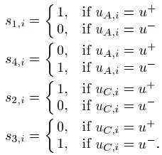
Again, if dc voltages are sufficiently high, the reaching condi-tion is satisfied, allowing sliding surface to be reached in fi-nite time. Direct application of (29) would require an infifi-nite switching frequency. In practical realization, an hysteresis band is considered in order to provide a finite and sufficiently low switching frequency. Gate signals for k-th inverter are easily derived from (10) and (29) as follows:
(30)
III. CONVERTERTOPOLOGY, SSSC OPERATION ANDCONTROL
[image:6.594.105.219.546.655.2]The series connected converter is reported in Fig. 5. Apart from network connection, the converter and the filtering interface are the same as those already described for the STATCOM, thus their functions and equations will no be repeated here. The role of a series compensator is to provide a capacitive compensation for long transmission lines. As for STATCOM,
Fig. 6. Phasor diagram illustrating SSSC operation in capacitive compensation mode.
besides the main objective, supplementary controls could be added to provide additional capabilities such as current, power flow control, and damping of power oscillations. Although capacitive compensation is the most common operation of the SSSC, inductive compensation could be required in some circumstances, as well.
The phasor diagram reported in Fig. 6 illustrates the principle of capacitive compensation of SSSC, which injects three-phase voltages rad lagging line currents. Again, an angle is required for active power to flow into the converter in order to compensate for losses.
The following relationships, assuming balanced three-phase capacitive operation, are easily derived:
(31)
Injected series voltage is
Fig. 7. The 230-kV test system for STATCOM simulation.
where is the desired compensator equivalent reactance. The magnitude and phase of converter output reference voltage are
(33)
(34)
Again, and can be derived by phase shifting by and rad, respectively.
The control strategy for SSSC operation is the same as for STATCOM, as illustrated in Fig. 4, except for reference voltages derived from the desired equivalent series reactance.
IV. NUMERICALSIMULATIONS
Numerical simulations for both compensators are reported in the following.
A. STATCOM
The test system reported in Fig. 7, adapted from [14], is em-ployed for STATCOM simulation. It consists of a three-phase 230-kV ideal generator which feeds a load area through a transmission line and a step-down transformer. Three loads are switched sequentially, in order to provide different operating conditions. The proposed STATCOM is shunt connected to bus through a coupling transformer. Network data are reported in Fig. 7 while the converter and controller data are given in Appendix B. The converter utilized in numerical simulations is constituted by three parallel-connected inverters.
Load is connected from the beginning of simulation. At s, a second inductive load is connected, while load which has a capacitive component is switched on at
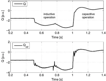
s. At s, loads and are both disconnected, leaving only the capacitive load, resulting in inductive operation of the STATCOM, as shown in Fig. 8, where both measured reactive power absorbed by the converter and its reference are shown.
[image:7.594.324.530.68.225.2]The magnitude of voltage at the regulated bus and the magnitude of the current absorbed by the STATCOM are plotted in Fig. 9. Dc capacitor voltages and the angle are shown in Fig. 10.
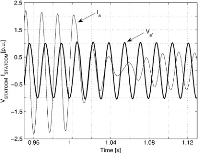
Phase voltage and current at STATCOM output at the passage from capacitive (voltage lagging) to inductive (voltage leading) mode of operation are reported in Fig. 11.
Rms values of phase output current of the three converters are reported in Fig. 12. Despite different values for filter
[image:7.594.323.530.271.433.2]induc-Fig. 8. Actual (top) and reference (bottom) reactive power absorbed by the STATCOM.
[image:7.594.323.530.474.634.2]Fig. 9. Magnitude of voltage (top) and current (bottom) at STATCOM output.
Fig. 10. DC capacitors voltages (top) and angle(bottom).
tances, the current sharing is good. A higher number of par-allel-connected inverters could be easily added to lower the cur-rent through each of them.
GRIFFO AND LAURIA: TWO-LEG THREE-PHASE INVERTER CONTROL FOR STATCOM AND SSSC APPLICATIONS 367
[image:8.594.319.531.67.245.2]Fig. 11. PhaseaSTATCOM voltage and current.
Fig. 12. Current rms in filter inductances.
Fig. 13. v (top) andv (bottom).
Sliding-mode control results in a variable switching frequency. By means of a running window, the number of commutations in a period has been evaluated and its maximum has been found to result in a maximum switching frequency as low as 1250 Hz.
B. SSSC
The test system used in SSSC simulations is reported in Fig. 15, [14]. Different operating conditions are tested by
Fig. 14. THD of busB voltage.
[image:8.594.64.262.259.415.2]Fig. 15. 230-kV test system for SSSC simulation.
Fig. 16. SSSC equivalent reactance (top). Active and reactive power absorbed by SSSC (bottom).
[image:8.594.322.525.375.533.2] [image:8.594.61.266.452.622.2]Fig. 17. Magnitude of injected voltage (top) and current through SSSC (bottom).
[image:9.594.325.529.67.222.2]Fig. 18. Dc capacitors voltages (top) and angle(bottom).
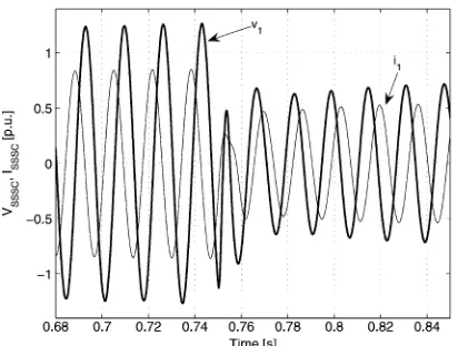
Fig. 19. Phase 1 SSSC voltage and current.
are obtained with respect to output voltages with a switching frequency lower than 1250 Hz, which result in a THD level well below 0.1%.
V. CONCLUSION
[image:9.594.62.266.269.425.2]In this paper, a converter constituted by the parallel operation of basic building blocks is utilized for both series and parallel reactive power compensation, thus proposing an alternative
Fig. 20. Current rms in filter inductances.
topology for FACTS devices. Each building block is the most basic two-leg three-phase inverter constituted by four switches and a split capacitor. The compensation problem is translated into the task of tracking reference three-phase voltages at converter output. Recognizing the variable structure nature of the converter, the tracking problem is tackled by means of a sliding controller, which also provide a solution to the problem of a balanced current sharing among the two-leg parallel con-nected inverters. Numerical simulations are reported both for a STATCOM and a SSSC based on the proposed converter, showing simplicity both in control and converter topology, as well as effective tracking performance of the sliding controller.
APPENDIXA LIST OFSYMBOLS
A list of symbols used throughout the paper is given next:
line to line compensator output voltages;
line to line compensator output reference voltages;
line to ground network voltages;
currents drawn by the STATCOM;
reference currents to be drawn by the STATCOM;
positive sequence network voltage magnitude;
reference STATCOM active and reactive power;
equivalent SSSC reactance;
SSSC injected series voltages;
network line currents;
complement of the angle between and
[image:9.594.63.269.459.615.2]GRIFFO AND LAURIA: TWO-LEG THREE-PHASE INVERTER CONTROL FOR STATCOM AND SSSC APPLICATIONS 369
coupling transformer leakage resistance, inductance, and reactance;
PI regulators constant gains;
output filter inductances of k-th inverter;
output filter capacitances;
output filter currents of k-th inverter;
output filter capacitances currents;
dc voltages;
control input to k-th LC filter;
maximum positive voltage at LC filter input;
minimum negative voltage at LC filter input;
k-th inverter switches binary gate control signals;
matrices of state-space representation in (13);
switching surface (17);
transformed switching surface (24).
APPENDIXB
Matrix in (24) is given by (27)
(35)
where
(36)
and
..
. . .. ...
..
. . .. ...
(37)
..
. . .. ...
..
. . .. ...
(38)
TABLE I
STATCOM CONVERTERDATA
TABLE II
STATCOM PI CONTROLLERDATA
TABLE III
STATCOM SLIDINGMODECONTROLLERDATA
TABLE IV SSSC CONVERTERDATA
TABLE V SSSC PI CONTROLLERDATA
TABLE VI
SSSC SLIDINGMODECONTROLLERDATA
It results in
(39)
and analogously
(40)
APPENDIXC DATA
STATCOM converter data used in simulations are given in Table I, while STATCOM controllers data are reported in Tables II and III.
REFERENCES
[1] E. Acha, C. R. Fuerte-Esquivel, H. Ambriz-Perez, and C. Angeles-Camacho, FACTS: Modelling and Simulation in Power Networks. Chichester, U.K.: Wiley, 2004.
[2] V. K. Sood, HVDC and FACTS Controllers. Applications of Static Con-verters in Power Systems. Boston, MA: Kluwer, 2004.
[3] P. Moore and P. Ashmole, “Flexible AC transmission systems,”Power Eng. J., vol. 9, no. 6, pp. 282–286, Dec. 1995.
[4] P. Kundur, Power System Stability and Control. New York: McGraw-Hill, 1994.
[5] G. Rogers, Power System Oscillations. Boston, MA: Kluwer, 2000. [6] L. Gyugyi, “Power electronics in electric utilities: Static VAR
compen-sators,”Proc. IEEE, vol. 76, no. 4, pp. 483–494, Apr. 1988. [7] K. K. Sen, “STATCOM-STATic COMpensator: Theory, modeling and
applications,”IEEE Trans. Power Del., vol. 2, no. 1, pp. 1177–1183, Feb. 1999.
[8] K. K. Sen, “SSSC-static synchronous series compensator: Theory, modeling and applications,”IEEE Trans. Power Del., vol. 13, no. 1, pp. 241–246, Jan. 1998.
[9] K. K. Sen and E. J. Stacey, “UPFC-unified power flow controller: Theory, modeling and applications,”IEEE Trans. Power Del., vol. 13, no. 4, pp. 1453–1460, Oct. 1998.
[10] L. Chen, Y. Liu, A. B. Arsoy, P. F. Ribeiro, M. Steurer, and M. R. Ira-vani, “Detailed modeling of superconducting magnetic energy storage (SMES) system,”IEEE Trans. Power Del., vol. 21, no. 2, pp. 699–710, Apr. 2006.
[11] D. Soto and T. C. Green, “A comparison of high-power converter topologies for the implementation of FACTS controllers,”IEEE Trans. Ind. Electron., vol. 49, no. 5, pp. 1072–1080, Oct. 2002.
[12] Y. Ye, M. Kazerani, and V. H. Quintana, “Current-source converter based STATCOM: Modeling and control,”IEEE Trans. Power Del., vol. 20, no. 2, pp. 795–800, Apr. 2005.
[13] A. H. Norouzi and A. M. Sharaf, “Two control schemes to enhance the dynamic performance of the STATCOM and SSSC,”IEEE Trans. Power Del., vol. 20, no. 1, pp. 435–442, Jan. 2005.
[14] M. S. El-Moursi and A. M. Sharaf, “Novel controllers for the 48-pulse VSC STATCOM and SSSC for voltage regulation and reactive power compensation,”IEEE Trans. Power Syst., vol. 20, no. 4, pp. 1985–1997, Nov. 2005.
[15] M. S. El-Moursi and A. M. Sharaf, “Novel reactive power controllers for the STATCOM and SSSC,”Electr. Power Syst. Res., vol. 76, no. 4, pp. 228–241, Jan. 2006.
[16] J. Rodriguez, J. S. Lai, and F. Z. Peng, “Multilevel inverters: A survey of topologies, controls, and applications,”IEEE Trans. Ind. Electron., vol. 49, no. 4, pp. 724–738, Aug. 2002.
[17] C. K. Lee, J. S. K. Leung, S. Y. R. Hui, and H. S.-H. Chung, “Cir-cuit-level comparison of STATCOM technologies,”IEEE Trans. Power Electron., vol. 18, no. 4, pp. 1084–1092, Jul. 2003.
[18] P. K. Steimer, H. E. Grüning, J. Werninger, E. Carroll, S. Klaka, and S. Linder, “IGCT: A new emerging technology for high power, low cost inverter,” inProc. 32nd Industrial Applications Soc. Annu. Meeting, New Orleans, LA, Oct. 1997, vol. 2, pp. 1592–1599.
[19] P. K. Steimer, O. Apeldoorn, and E. Carroll, “IGCT devices—applica-tions and future opportunities,” inProc. IEEE Power Eng. Soc. Summer Meeting, Seattle, WA, Jul. 2000, vol. 2, pp. 1223–1228.
[20] Y. Li, A. Q. Huang, and K. Motto, “Analysis of the snubberless opera-tion of the emitter turn-off thyristor (ETO),”IEEE Trans. Power Elec-tron., vol. 18, no. 1, pp. 30–37, Jan. 2003.
[21] B. Zhang, A. Q. Huang, Y. Liu, and S. Atcitty, “Performance of the new generation emitter turn-off (ETO) thyristor,” inProc. 37th IAS Annu. Meeting, 2002, vol. 1, pp. 559–563.
[22] B. Zhang, A. Q. Huang, Y. Liu, B. Chen, and S. Atcitty, “SPETO: A superior power switch for high power, high frequency, low cost converters,” inProc. 39th IAS Annu. Meeting, Oct. 2004, vol. 3, pp. 1940–1946.
[23] J. Y. Hung, W. Gao, and J. C. Hung, “Variable structure control: A survey,”IEEE Trans. Ind. Electron., vol. 40, no. 1, pp. 2–22, Feb. 1993. [24] R. A. DeCarlo, S. H. Zak, and G. P. Matthews, “Variable structure con-trol of nonlinear multivariable systems: A tutorial,”Proc. IEEE, vol. 76, no. 3, pp. 212–232, Mar. 1988.
[25] F. Blaabjerg, S. Freysson, H. H. Hansen, and S. Hansen, “A new op-timized space-vector modulation strategy for a component-minimized voltage source inverter,”IEEE Trans. Power Electron., vol. 12, no. 4, pp. 704–714, Jul. 1997.
[26] E. Ledezma, B. McGrath, A. Munoz, and T. A. Lipo, “Dual AC-drive system with a reduced switch count,”IEEE Trans. Ind. Appl., vol. 37, no. 5, pp. 1325–1333, Sep. 2001.
[27] G. T. Kim and T. A. Lipo, “VSI-PWM rectifier-inverter system with a reduced switch count,”IEEE Trans. Ind. Appl., vol. 32, no. 6, pp. 1331–1337, Nov. 1996.
[28] B. R. Lin and T. C. Wei, “A novel NPC inverter for harmonics elimina-tion and reactive power compensaelimina-tion,”IEEE Trans. Power Del., vol. 19, no. 3, pp. 1449–1456, Jul. 2004.
[29] V. I. Utkin, J. Guldner, and J. Shi, Sliding Mode Control in Electro-mechanical Systems. London, U.K.: Taylor & Francis, 1999. [30] A. G. Loukianov, J. M. Canedo, V. I. Utkin, and J. Cabrera-Váazquez,
“Discontinuous controller for power systems: Sliding-mode block con-trol approach,”IEEE Trans. Ind. Electron., vol. 51, no. 2, pp. 340–353, Apr. 2004.
[31] V. I. Utkin, “Sliding mode control design principles and applications to electric drives,”IEEE Trans. Ind. Electron., vol. 40, no. 1, pp. 23–36, Feb. 1993.
[32] R. Ramos, D. Biel, F. Guinjoan, and E. Fossas, “Design considerations in sliding-mode controlled parallel-connected inverters,”in Proc. IEEE ISCAS, no. 4, pp. 357–360, 2002.
[33] M. Carpita and M. Marchesoni, “Experimental study of a power condi-tioning system using sliding mode control,”IEEE Trans. Power Elec-tron., vol. 11, no. 5, pp. 731–742, Sep. 1996.
[34] H. Sira-Ramirez, “Sliding motions in bilinear switched networks,”
IEEE Trans. Circuits Syst., vol. 34, no. 8, pp. 919–933, Aug. 1987.
Antonio Griffowas born in Torino, Italy, in 1978. He received the Master’s degree in electronic engi-neering and the Ph.D. degree in electrical engiengi-neering from the University of Naples “Federico II”, Naples, Italy, in 2003 and 2007, respectively.
Currently, he is a Research Associate at the University of Sheffield, Sheffield, U.K., working on power system stability analysis for the More Electric Aircraft. His research interests include modeling, and stability analysis and control of power systems and power electronics.
Davide Lauriareceived the electrical engineering degree (Hons.) and the Master’s degree in math-ematics (Hons.) from the University of Naples “Federico II,” Naples, Italy, in 1987 and 1995, respectively.