HCCI Engine: Numerical and
Experimental Approach
A. Aziz Hairuddin
Talal F. Yusaf
Andrew P. Wandel
Outline
Introduction
Numerical Approach
Model formulation
Results and analysis
Experimental Approach
Engine Diagram
Preliminary test
Introduction
What is HCCI engine?
It stands for Homogeneous Charge Compression Ignition engines.
First research was started by Onishi et al. in 1979.
This engine has been investigated worldwide as this technology has not matured
sufficiently.
It could be used in either SI or CI configurations with high compression ratio (CR)
In principle, there is no spark plug or injector inside the combustion chamber like
Introduction
What is the difference?
SI engines: Requires spark plug and low CR CI engines: Requires fuel injector and high CR
HCCI engines: Without spark plugs or fuel injectors. Can be configured using CI or SI mode with high CR – leads to high engine efficiency with low emissions level.
Source: Lawrence Livermore National Laboratory, https://www-pls.llnl.gov/?url=science_and_techno
Introduction
Combustion behaviour:
SI engines: It has flame propagation with longer combustion period CI engines: Auto-ignite when the fuel is injected into hot compressed air
HCCI engines: Auto-ignite in multiple spots instantaneously with fast combustion period
Source: Engine Research Centre, University of Wisconsin,
Introduction
Homogeneous charge engine types
HCCI [69]
Homogeneous-charge spark-ignition [69]
Stratified-charge spark-ignition [69]
Spark-induced
compression-ignition [66]
PCCI, SCCI [69]
Flame propagation
Auto-ignition
Introduction
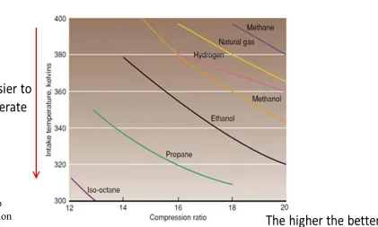
HCCI engines can operate using any type of fuels as long as the fuel can be vaporized and mixed with air before the ignition.
Fuel auto-ignition point is important to look at in order to get smooth engine operation: Different fuels will have different auto-ignition points as shown in below figure.
Figure Intake temperatures required for fuels to operate under HCCI mode with various compression
[image:7.720.278.699.213.466.2]Introduction
HCCI advantages:
High engine efficiency relative to SI engines by employing high CR and fast
combustion [2,3].
Ability to operate using a wide range of fuels [4].
Can be implemented in any engine configuration: automobile engines, stationary
engines, high load engines or small size engines [5,6]
HCCI disadvantages:
Difficulties in controlling the auto-ignition and heat release rate at high load
operation and achieving cold start [7,8].
Knocking due to sudden onset of the combustion behaviour, which reduces
Introduction
HCCI challenge:
To control the auto-ignition timing of the mixture because
there is no spark plug or fuel injector to control the start of
the combustion.
To achieve cold start.
To meet emission standards.
Numerical Approach
Zero-Dimensional Model without Turbulence and Mixing
Model Formulation
Conservation of mass: 𝑑𝑚
𝑑𝑡 = 𝑚 𝑗 𝑗
Conservation of species:
An n-heptane reduced chemical reaction mechanism was used [13].
The properties are similar to conventional diesel (e.g. cetane number) Consists of 160 species and 770 elementary reactions
𝑑𝑌𝑖
𝑑𝑡 =
𝜔 𝑊𝑖 𝑖
𝜌 , 𝑖 = 1, … , 𝑛
Gas exchange process:
A gas exchange process takes place when inlet or exhaust valve is open.
Model Formulation
Conservation of energy:
The equation was derived from the first law of thermodynamics for an
open system to get the change in temperature.
𝑑𝑇
𝑑𝑡 = 1
𝐶𝑝−𝑃𝑣𝑇 − 𝐻𝑖 −
𝑃𝑣 𝑖𝑅𝑢 𝑊
𝑅𝑢 𝑊
𝑑𝑌𝑖 𝑑𝑡 −
𝑚
𝑚 ℎ𝑗 − 𝑃𝑣 + 1
𝑚 𝑚 𝑗ℎ𝑗 − 𝑃 𝑑𝑉
𝑑𝑡 + 𝑑𝑄
𝑑𝑡
Where the pressure was calculated using the ideal gas law equation: 𝑃 = 𝜌𝑇𝑅𝑢
𝑊
Heat transfer:
Heat is transferred to the wall through convection and radiation.
Radiation heat transfer on HCCI engines is neglected because the effect is
very small, due to low soot and low temperature combustion [14,15]
Results and Analysis
Validation
The model was validated against numerical and experimental data from
Guo et al. [17]: the fuel was injected at inlet manifold.
To account for mixing effects: the effective intake temperature was set
20°C higher than the intake temperature [17].
Cylinder bore 82.55 mm
Stroke 114.3 mm
Connecting rod length 254 mm
Compression ratio 10
Engine speed 900 rpm
Inlet valve open (IVO) 10° CA ATDC
Inlet valve closed (IVC) 36° CA ABDC
Exhaust valve open (EVO) 40° CA BBDC
[image:13.720.141.578.256.488.2]Exhaust valve closed (EVC) 5° CA ATDC
Results and Analysis
Validation
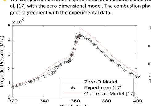
The comparison between experimental and numerical data from Guo et
al. [17] with the zero-dimensional model. The combustion phasing is in good agreement with the experimental data.
320 340 360 380 400
0 1 2 3 4
5 x 10
6 Crank Angle In -cyl in de r P re ssu re ( M P a) Zero-D Model Experiment [17]
[image:14.720.53.543.132.475.2]Guo et al. Model [17]
Figure 1 Comparison between single-zone
zero-dimensional model with experiment
and another single-zone model using modified Woschni heat
transfer model [17]. CR=10.0, N=900 rpm,
Results and Analysis:
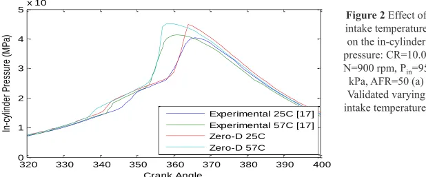
Effect of intake temperature
Auto-ignition can be advanced once the intake temperature is increased.
Results from the current simulation were compared with experimental results [17] in Fig. 2(a) to validate the model over different operating temperatures: The results agreed well as did in Fig. 1.
320 330 340 350 360 370 380 390 400 0
1 2 3 4 5 x 10
6 Crank Angle In -cyl in de r P re ssu re ( M P a)
Experimental 25C [17] Experimental 57C [17] Zero-D 25C
Zero-D 57C
[image:15.720.69.687.226.483.2](a)
Figure 2 Effect of intake temperature on the in-cylinder pressure: CR=10.0, N=900 rpm, Pin=95
Results and Analysis:
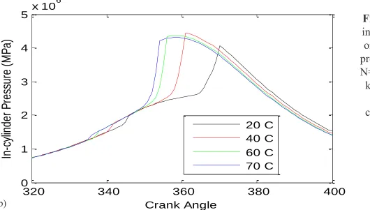
Effect of intake temperature
320 340 360 380 400
0 1 2 3 4
5 x 10
[image:16.720.57.587.178.479.2]6 Crank Angle In -cyl in de r P re ssu re ( M P a) 20 C 40 C 60 C 70 C
Figure 2 Effect of intake temperature on the in-cylinder pressure: CR=10.0, N=900 rpm, Pin=95 kPa, AFR=50 (b)
Predicted in-cylinder pressure
trend.
(b)
The predicted in-cylinder peak pressure starts to decrease even
Results and Analysis:
Effect of equivalence ratio
The equivalence ratio (Φ) is a measure of how much fuel and air is being consumed in the combustion chamber.
Figure 3(a) shows validated result of different equivalence ratios compared to the experiment, again showing good agreement.
320 330 340 350 360 370 380 390 400
0 1 2 3 4 5x 10
6 Crank Angle In -cyl in d e r P re ssu re ( M P a )
Experimental at 0.35 [17] Zero-D at 0.35
Experimental at 0.3 [17] Zero-D at 0.3
[image:17.720.61.473.223.481.2](a)
Figure 3 Effect of equivalence ratio on the in-cylinder pressure: CR=10.0, N=900 rpm, Tin=40°C, Pin=95
Results and Analysis:
Effect of equivalence ratio
320 340 360 380 400
0 1 2 3 4 5
6 x 10
[image:18.720.59.523.171.477.2]6 Crank Angle In -cyl in d e r P re ssu re ( M P a ) 0.25 0.3 0.4 0.5
Figure 3 Effect of equivalence ratio on the
in-cylinder pressure: CR=10.0, N=900 rpm, Tin=40°C, Pin=95 kPa (b)
Predicted in-cylinder pressure trend.
(b)
The in-cylinder peak pressure trend keeps increasing with increasing
equivalence ratio: will create knocking.
Results and Analysis:
Effect of hydrogen addition
Effective way to reduce ignition delay and improves engine efficiency [19].
Too much hydrogen will create knocking: the energy ratio should be less than 15% [20].
The auto-ignition point is advanced significantly with 1% hydrogen and the in-cylinder peak pressure keeps increasing with increasing hydrogen content.
320 340 360 380 400
0 1 2 3 4
[image:19.720.64.563.229.476.2]5 x 10 6 Crank Angle In -cyl in de r P re ssu re (M Pa ) n-heptane 1% H2 5% H2 15% H2
Figure 4 Predicted effect of hydrogen addition on the in-cylinder pressure for
fixed n-heptane injection: CR=10.0,
Experimental Approach
Engine: Single cylinder SI engine to be
converted to HCCI engine
External heater to be installed on the
intake air manifold
Hydrogen will be added later on: if the
Experimental Approach
1 Engine
2 Dynamometer
3 Data logger
4 Fuel tank
5 ECU
6 Hydrogen electrolyser
7 Fuel injector
8 Hydrogen injector
9 Air intake heater
10 Airflow meter
Experimental Approach
Experimental Approach
Experimental Approach
Experimental Approach
Next modification:
Carburetor system replaced by
injector system
New 2kW heater installed before
the injector
Wideband lambda sensor will be
Conclusion
HCCI: high combustion efficiency, low emissions levels, can use any fuels
Numerical:
Once the intake temperature is increased above a certain threshold, the in-cylinder peak pressure will decrease with increasing intake temperature.
The in-cylinder peak pressure keeps increasing with increasing equivalence ratio: will create knocking.
Increasing the hydrogen content will also increase the in-cylinder peak pressure: should be no more than 20%
In summary, the combustion phasing is advanced by increasing all the parameters (intake temperature, equivalence ratio and energy ratio).
Experimental:
Engine setup has to be completed as soon as possible: workshop work for a new heater is pending. ETA in 2 - 4 weeks!
![Table 1 Engine parameter used in the simulation [17]](https://thumb-us.123doks.com/thumbv2/123dok_us/165336.42480/13.720.141.578.256.488/table-engine-parameter-used-in-the-simulation.webp)