i
Improving High Voltage Power System Performance
Using Arc Suppression Coils
by
Robert Thomas Burgess B Com MIEAust CPEng RPEQ
A Dissertation
Submitted in Fulfilment
of the Requirements
for the degree of
Doctor of Philosophy
at the
University of Southern Queensland
Faculty of Engineering & Surveying
ii
ABSTRACT
Arc suppression coils provide a low cost method of increasing both the reliability and safety of high voltage transmission and distribution systems. Although the concept is not new, the advent of modern control equipment allows fresh opportunities for them to be used to save lives and to decrease the cost and
inconvenience to industry and the community in general that is caused by electricity supply interruptions without incurring large expenditure. Earth fault currents are reduced to almost zero, thus eliminating many short time power supply interruptions and preventing damage to the electricity supply system at the time of the initial fault. Because of the reduction in damage at the time of the fault, many longer duration interruptions are avoided. It is common for live high voltage conductors to be close to the ground and for the fault not to be detected by conventional power system protection equipment. Arc suppression coil systems can detect high impedance earth faults and broken conductors which cannot be detected by conventional protection systems.
There are many system abnormalities which can cause neutral voltages in arc
suppression coil systems. The appropriate action to be taken by the protection system depends on the type of system abnormality. The causes of neutral voltages in arc suppression coil systems are analysed and criteria are developed to differentiate between them based on the phase angle and magnitude of the neutral voltage. Fully computerised power system protection systems are now being implemented. These modern protection systems will be able to utilise the criteria developed in this
research to take immediate appropriate action based on the neutral voltage caused by the system abnormality.
In existing distribution systems there is a widespread use of two single phase pole mounted auto-transformers connected in open-delta configuration to provide
economic in-line three phase voltage regulation. An original method of representing open delta regulators in symmetrical component analyses is developed. It is shown that when open-delta regulators are used in a power system equipped with an arc suppression coil very high voltages can occur. A solution is proposed whereby three single phase pole mounted auto-transformers connected in a closed-delta
arrangement are used.
iii
CERTIFICATION OF DISSERTATION
I certify that the ideas, experimental work, results, analyses, software and
conclusions reported in this dissertation are entirely my own effort except where otherwise acknowledged. I also certify that the work is original and has not been previously submitted for any other award except where otherwise acknowledged.
__________________________ ________________
Signature of Candidate Date
ENDORSEMENT
__________________________ ________________
__________________________ ________________
iv
ACKNOWLEDGMENTS
I sincerely acknowledge and thank the following people for their assistance, guidance, support and encouragement throughout the duration of this project. My supervisor, Dr Tony Ahfock, provided in depth assistance and guidance throughout the project. He always maintained a keen interest in the work and went out of his way to make himself available for consultation whenever I needed it. This work has been discussed in detail with Tony and reviewed by him as the project progressed.
Other academic and technical university staff provided support, technical facilities and most welcome words of encouragement.
Steve Macdonald and Taz Scott of Orion New Zealand Limited showed me one of their existing Earth Fault Neutralizer installations and provided invaluable
information on their operating experience.
Ergon Energy staff provided access to the high voltage testing facility and invaluable assistance with the high voltage tests.
v
CONTENTS
ABSTRACT ... ii
CERTIFICATION OF DISSERTATION ... iii
ACKNOWLEDGMENTS ... iv
CONTENTS ... v
LIST OF FIGURES ... ix
LIST OF TABLES ... xiii
PUBLICATIONS ... xiv
Chapter 1 JUSTIFICATION FOR THE PROJECT ... 1
1.1 Principle of operation of arc suppression coils... 1
1.2 Reasons for using arc suppression coils ... 1
1.3 Current Usage of arc suppression coils ... 2
1.4 Aim of the research ... 3
1.4.1 Analysis of neutral voltages and appropriate responses. ... 3
1.4.2 In-line single phase voltage regulators ... 3
1.4.3 Minimising cross-country faults caused by voltage transients ... 4
1.5 Outline of dissertation ... 6
1.5.1 Analysis of neutral voltages ... 6
1.5.2 In-line single phase voltage regulators ... 6
1.5.3 Minimising cross-country faults caused by voltage transients ... 6
1.6 Summary of research outcomes... 6
1.6.1 Analysis of neutral voltages ... 6
1.6.2 In-line single phase voltage regulators ... 6
vi
Chapter 2 LITERATURE REVIEW AND SCOPE ... 8
2.1 Usage of arc suppression coils ... 8
2.2 Analysis of neutral voltages ... 9
2.3 In-line single phase voltage regulators ... 10
2.4 Minimising Cross Country Faults ... 10
Chapter 3 METHODOLOGY ... 12
3.1 Analysis of neutral voltages ... 12
3.2 In-line single phase voltage regulators ... 12
3.3 Minimising cross country faults ... 13
Chapter 4 ANALYSIS OF NEUTRAL VOLTAGES ... 14
4.1 An accurately tuned simple system ... 14
4.2 Causes of abnormal neutral voltages ... 19
4.2.1 A line to earth fault. ... 19
4.2.2 Out of balance in the line to earth capacitance. ... 19
4.2.3 An open circuit in one phase line ... 19
4.3 A line to earth fault ... 19
4.4 A disturbance in the line to earth capacitance balance. ... 21
4.5 An open circuit ... 24
4.5.1 An open circuit in one phase with no earth fault ... 25
4.5.2 The effect of distributed generation. ... 28
4.5.3 Open circuit with a line to earth fault... 31
4.6 Appropriate actions to take on detecting an abnormal neutral voltage. ... 35
4.7 Evaluation of fault and appropriate actions ... 37
vii Chapter 5 IN-LINE VOLTAGE REGULATORS ... 41
5.1 Open-delta regulators ... 41 5.1.1 Modelling of open-delta regulators using symmetrical components ... 44 5.1.2 Analysis of a simple system with open delta regulators ... 48 5.2 Three star connected auto-transformers ... 56
5.2.1 Three star connected single phase auto-transformers with the star point earthed... 57 5.2.2 Three star connected single phase auto-transformers with the star point unearthed ... 59 5.3 Three delta connected single phase auto-transformers. ... 61
5.3.1 Modelling of three delta connected auto-transformers using
viii
Chapter 6 MINIMISING CROSS COUNTRY FAULTS ... 82
6.1 A radial line without any branches ... 83
6.1.1 The worst case scenario for the peak voltages ... 84
6.1.2 Estimation of frequency and decay time for a typical 11 kV overhead line type. ... 88
6.1.3 Approximate methods for transient voltage estimation ... 91
6.2 Typical zone substation distribution systems ... 93
6.3 Implications for existing systems ... 96
6.4 Testing of system components ... 97
6.5 Proposed method of controlling transient over-voltages ... 98
6.6 Summary ... 101
Chapter 7 CONCLUSIONS AND FURTHER WORK ... 102
7.1 Analysis of neutral voltages ... 102
7.2 In-line single phase voltage regulators ... 102
7.3 Minimising cross country faults ... 103
7.4 Cost benefit analyses ... 103
Chapter 8 REFERENCES ... 105
APPENDIX A1 ... 111
ANALYSIS OF AN OPEN CIRCUIT COMBINED WITH LINE TO EARTH FAULTS. ... 111
A1.1 Unknown quantities and equations ... 111
A1.2 A matlab script to solve the equations ... 113
APPENDIX A2 ... 115
ix
LIST OF FIGURES
Figure 1.1 Connection diagram of a high voltage open-delta voltage regulator. ... 4 Figure 1.2 Typical line voltages before and after a single phase to earth fault on an 11 kV distribution system fitted with an arc suppression coil. ... 5 Figure 4.1 Simple single line power system. ... 14 Figure 4.2 Symmetrical component network for the simple system with a single line to earth fault at the load end. ... 16 Figure 4.3 Fault currents for the simple system with a low impedance single line to earth fault and with various values of arc suppression coil parameters. ... 17 Figure 4.4 Neutral voltages for the simple system with various resistances of single line to earth faults and with various values of arc suppression coil parameters. ... 18 Figure 4.5 Neutral voltage for a simulated single line to earth fault varying from zero to 1 MΩ, and with faults on each phase line in turn. The reference phase angle is A to N. ... 20 Figure 4.6 Urban Zone substation area 11 kV network. ... 21 Figure 4.7 Symmetrical component network for the simple system with an out of balance line to earth capacitance. ... 22 Figure 4.8 Neutral voltage for a simulated out of balance capacitance varying from plus 10% of 0
L
C to minus 10% of 0
L
x Figure 4.15 Sequence network for the simple system with an open circuit in one
conductor and with isolated three phase generation on the load side. ... 29
Figure 4.16 Sequence network for the simple system with an open circuit in one conductor, with line inductances and all losses ignored and with isolated three phase generation on the load side. ... 30
Figure 4.17 EMTP representation of an open circuit in one phase line and isolated generation. ... 31
Figure 4.18 Sequence network for the simple system with an open circuit and simultaneous single line to earth faults at the same location and in the same conductor. ... 32
Figure 4.19 Neutral voltage for an open circuit at three locations, and a line to earth fault at the same location on the load side varying from zero to 1 MΩ, and with faults on each phase line in turn. The reference phase angle is A to N. ... 33
Figure 4.20 Neutral voltage for an open circuit at three locations, and a line to earth fault at the same location on the source side varying from zero to 1 MΩ, and with faults on each phase line in turn. The reference phase angle is A to N. ... 34
Figure 4.21 Bypassing of arc suppression coil... 35
Figure 4.22 Possible fault types and appropriate actions deduced from the neutral voltage. ... 38
Figure 4.23 Logic for taking action on the basis of the neutral voltage... 39
Figure 5.1 Open-delta regulator connections. ... 41
Figure 5.2 Pole mounted open-delta regulator. ... 42
Figure 5.3 Voltage phasor diagram for an open-delta regulator. ... 43
Figure 5.4 Symmetrical component representation of an open-delta regulator. ... 48
Figure 5.5 Simple 11 kV System showing zero sequence and earthing components. ... 49
Figure 5.6 Symmetrical component representation of a simple system with an open-delta voltage regulator. ... 50
Figure 5.7 Sequence network representation of the simple system with an open-delta regulator referred to the zero sequence side. ... 51
Figure 5.8 EMTP Representation of the simple system with an open-delta voltage regulator. ... 52
Figure 5.9 Sequence Network for the simple system with line inductances and all losses ignored. ... 53
xi Figure 5.11 Magnetizing curve of the earthing inductor... 55 Figure 5.12 Phase voltages for the simple system with a practical, saturable earthing inductor and a voltage regulator ratio of 1.1. ... 56 Figure 5.13 Two auto-transformers mounted on a single pole ... 56 Figure 5.14 Three auto-transformers mounted on a single pole. ... 57 Figure 5.15 Three star connected auto-transformer with the star point earthed voltage regulator connections. ... 58 Figure 5.16 Zero sequence representation of a three star connected auto-transformers with the star point earthed ... 58 Figure 5.17 Three star connected auto-transformers with the star point unearthed voltage regulator connections. ... 59 Figure 5.18 Zero sequence representation of a three star connected auto-transformers with the star point unearthed. ... 61 Figure 5.19 Three delta connected auto-transformers voltage regulator connections62 Figure 5.20 Phasor diagram for the normal operation of a three delta connected auto-transformer voltage regulator. ... 63 Figure 5.21. Currents in a three delta connected auto-transformer voltage regulator. ... 64 Figure 5.22. Zero sequence currents in a three delta connected auto-transformer voltage regulator... 65 Figure 5.23 Phasor diagram for a three delta connected auto-transformer voltage regulator with Pb greater than Pa and Pc. ... 69
Figure 5.24 Positive sequence voltage ratio provided by three delta connected auto-transformers... 71 Figure 5.25 Positive sequence voltage boost provided by three delta connected auto-transformers as a ratio of the voltage boost of each individual auto-transformer. ... 71 Figure 5.26 Three delta connected auto-transformers in a simple 11 kV system showing zero sequence and earthing components. ... 72 Figure 5.27 Zero sequence network of the simple system. ... 73 Figure 5.28 EMTP representation of three single phase delta connected
auto-transformers in the simple system. ... 75 Figure 5.29 Neutral voltage, for each auto-transformer in turn out of ratio by plus 10 %, and the portion of the network on the load side of the regulator varying
xiii
LIST OF TABLES
xiv
PUBLICATIONS
The following papers are direct outcomes of this research project. Published
[1] R. Burgess and A. Ahfock, "The use of arc-suppression coils in power systems with open-delta regulators," in Universities Power Engineering Conference (AUPEC), 2010 20th Australasian, pp. 1-6.
[2] R. Burgess and A. Ahfock, "Minimising the risk of cross-country faults in systems using arc suppression coils," Generation, Transmission & Distribution, IET, vol. 5, pp. 703-711.
[3] R. Burgess and A. Ahfock, "The use of voltage regulators in power systems with arc-suppression coils," in Universities Power Engineering Conference (AUPEC), 2011 21st Australasian
Under consideration for publication
1
Chapter 1
JUSTIFICATION FOR THE PROJECT
1.1 Principle of operation of arc suppression coils
Arc suppression coil systems are based on the Petersen coil principle that was invented in 1917 [1]. The high voltage system supply point neutrals are earthed through inductors which are tuned to the total line to earth capacitance of the system. When an earth fault occurs there is very little voltage on the faulted phase line and the voltages on the other phases and the neutral are displaced accordingly. This results in the normal line to line voltage being applied between the two healthy phase lines and earth for the duration of the fault. If the inductor is properly tuned the capacitive current resulting from the voltage displacement is equal and opposite to the current in the earthing inductor. The residual fault current will be very small and will not be sufficient to maintain an arc. There is therefore no arc or thermal damage at the point of the fault and many faults self extinguish. This can result in a
significant increase in system performance [2, 3]. Many high impedance line to earth faults cannot be detected by conventional power system protection schemes. In arc suppression coil systems a high impedance line to earth fault will cause a rise in the neutral voltage. By monitoring the neutral voltage these high impedance faults can be detected. This can greatly improve the system safety.
1.2 Reasons for using arc suppression coils
Reliability of electricity supply especially in rural areas is now becoming an
important issue because of the greater dependence on computers, internet access and general electrical equipment.
Arc suppression coil systems can greatly improve the reliability of supply for two main reasons.
2 2. Many of the line to earth faults develop into permanent faults because of the
damage caused by the fault current. These include distribution transformer fuses being blown by power arc current following lightning flashover and conductors being heated to the extent that they part under the normal line tension, and so on. These faults are avoided when an arc suppression coil system is installed because there is no significant fault current. There is a corresponding decrease in the cost of power system emergency repairs.
The community is regarding electricity safety as being of increasing importance because of a decreasing acceptance of accidental serious injury and death together with a greater reliance on the convenience of electrical appliances. Many situations where a live high voltage overhead conductor has come within reach of people on the earth cannot be detected by conventional protection systems that depend on a significant flow of current to earth. A large proportion of these faults can be detected in power systems incorporating arc suppression coils because there is a neutral voltage present for most broken conductor or high earth fault impedance faults. In response to a large loss of life and property in Victoria, Australia, in February 2009, caused by bushfires that were allegedly started by high voltage power line faults, the Victorian government has amended the relevant acts of parliament to mitigate the risks of bushfires being started by electric lines. As reported in [4], part of the Victorian government‟s submission to the Victorian Bushfires Royal
Commission included a recommendation for changes to power lines and distribution feeders which include “current and emerging methods of fault detection and fault level reduction‟. Arc suppression coils improve fault detection and also reduce fault levels.
1.3 Current Usage of arc suppression coils
Although the concept of arc suppression coils is not new there is renewed interest in them as a result of the increased emphasis on safety and reliability together with some of the enhancements now possible because of the use of solid state technology. Arc suppression coil systems have been used in some parts of continental Europe, but they have had very limited use in other places. The writer has personal
experience of an arc suppression coil installation in a 66 kV sub-transmission system in Queensland, Australia, being permanently taken out of service because of the incidence of cross-country faults.
3 1.4 Aim of the research
The aim of the research is to improve both reliability and safety of the power supply systems by enhancing the prospect of a wider application of the arc suppression coils. This involves;
a) Developing new ways for modern automatic protection systems to be programmed to take the appropriate action depending on the nature of the fault so as to gain further benefit from the installation of arc suppression coil systems.
b) Identifying various obstacles to the successful implementation of arc suppression coils systems and providing power system designers with practical tools and suggestions to design arc suppression coil systems which will operate successfully.
1.4.1 Analysis of neutral voltages and appropriate responses.
Objective 1 - Evaluate the causes of a sudden increase in the neutral voltage in high voltage systems fitted with arc suppression coils and show how this
information can be used to facilitate appropriate action by the automatic high voltage protection systems.
There are several types of abnormal power system conditions which can give rise to a sudden increase in the power system neutral voltage. It is shown that, in general, the type of abnormal system condition can be identified by the magnitude and the phase angle of the neutral voltage. By using the criteria developed in this research, power system protection engineers will be able to design the automatic protection systems to monitor the neutral voltage and to take appropriate action immediately. 1.4.2 In-line single phase voltage regulators
Objective 2 - Evaluate the likely over-voltages on high voltage distribution systems fitted with arc suppression coils when open delta connected single phase auto-transformers are used to provide in-line voltage regulation and seek an economic alternate method of providing in-line voltage regulation.
One of the difficulties to be overcome when installing arc suppression coils in rural high voltage distribution systems is the issues which arise with in-line
auto-transformer voltage regulation.
4 Va
Vc
Vb
VA
VB
VC
Ib
Ia
Ic
IB
IA
IC
Primary
Side
Secondary
Side
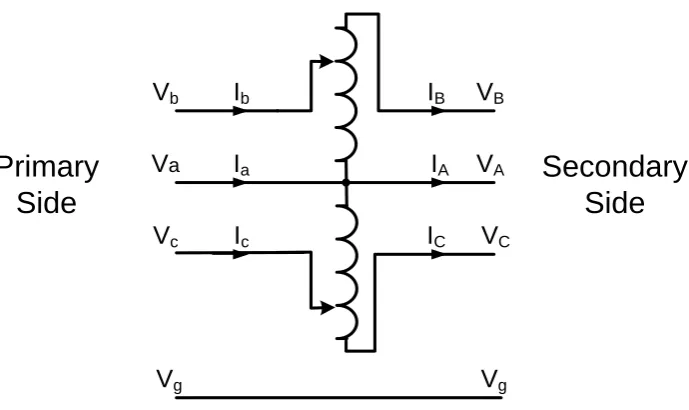
[image:18.595.139.484.68.273.2]Vg Vg
Figure 1.1 Connection diagram of a high voltage open-delta voltage regulator. Open-delta voltage regulators increase the line to earth voltage in two phases only. Because the line to earth voltages are no longer equal in magnitude, the line to earth capacitance currents will no longer add to zero. Current will therefore flow through the earthing inductor. As the inductance of the earthing coil is cancelled by the line to earth capacitances, the magnitude of current will only be limited by the resistance in the circuit and saturation of the magnetic core of the earthing inductor. This can result in excessive neutral voltage displacement and corresponding over-voltages in one or more of the phases. Depending on the system configuration the voltages can be high enough to cause insulation failures.
The older, more expensive, three phase auto-transformers cannot be used without impairing the effectiveness of the arc suppression coil system. Various options for providing in-line voltage regulation are analysed and a solution is proposed. 1.4.3 Minimising cross-country faults caused by voltage transients
Objective 3. - Research the causes of cross-country faults in high voltage power systems fitted with arc suppression coil systems and seek methods of reducing the incidence of them.
Cross-country faults have previously prevented the successful implementation of arc suppression coil systems. When a single phase line to earth fault occurs in a power supply system fitted with an arc suppression coil, the insulation on the other two phase lines is stressed. Typical voltages before and after a single phase to earth fault in an 11 kV distribution system with an arc suppression coil, as simulated
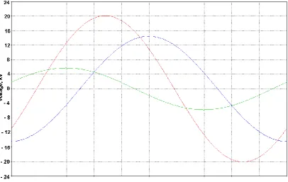
5 Figure 1.2 Typical line voltages before and after a single phase to earth fault on
an 11 kV distribution system fitted with an arc suppression coil. If a second earth fault occurs on another phase line there are then two faults usually on remote parts of the system. This is a phase to phase to earth fault. The earth component can be neutralised by the arc suppression coil but the line to line
component of the fault cannot be neutralised. There are then two parts of the system affected by faults and the situation is worse than it would have been if an arc
suppression coil had not been installed.
A previous installation of an arc suppression coil system in Queensland, Australia was permanently taken out of service because of simultaneous faults caused by the increased voltage on the two healthy phase lines, together with transient voltages, at the time of the fault.
6 1.5 Outline of dissertation
1.5.1 Analysis of neutral voltages
The neutral voltages which occur when a fault occurs in a power system fitted with an arc suppression coil are analysed in detail to find out whether the neutral voltage phase magnitude and phase angle can provide sufficient information for
computerised automatic protection systems to take appropriate action depending on the fault type.
1.5.2 In-line single phase voltage regulators
The over voltages that can occur during normal operation when two single phase auto-transformers connected in open-delta are used in a power system fitted with an arc suppression coil are analysed in detail and other methods of using single phase auto-transformers to provide in-line voltage regulation are assessed.
1.5.3 Minimising cross-country faults caused by voltage transients
The high transient voltages which can occur when a fault occurs in a power system fitted with an arc suppression coil are analysed in detail. Methods of reducing the cross-country faults caused by these transient voltages are proposed.
1.6 Summary of research outcomes 1.6.1 Analysis of neutral voltages
It is shown that, for power systems fitted with an arc suppression coil, the type of fault can be determined by monitoring the neutral voltage magnitude and phase angle. On the basis of this information, computerised protection systems can be programmed to take appropriate action automatically. A possible logic sequence for the automatic operation is proposed.
1.6.2 In-line single phase voltage regulators
7 1.6.3 Minimising cross-country faults caused by voltage transients
8
Chapter 2
LITERATURE REVIEW AND SCOPE
The principle of arc suppression coils has been known since 1917 [5]. Improvements in system performance with the use of the system have been documented [3, 4]. 2.1 Usage of arc suppression coils
Experience in the United States of America in the 1930s was that arc suppression coils could improve the performance of the transmission system[6]. It is reported in [7] that as the transmission system grew the expense of upgrading the arc
suppression coil systems was not warranted because more duplicate supplies were available.
As set out in [8], the reasons arc suppression coils have not been more widely used in Continental Europe include;
The reliability and sensitivity of conventional protection systems is decreased.
Permanent faults are more difficult to locate.
There is a need for a higher level of insulation.
There will be more cross-country faults.
9 2.2 Analysis of neutral voltages
Two common fault types which cannot easily be detected using conventional methods are:
1. High impedance earth faults, and 2. An open circuit in a conductor.
Arc suppression coil systems can detect high impedance faults because it takes only a small earth current to cause a voltage to appear across the tuned arc suppression coil. There has been recent work on detecting and locating high impedance faults. A means of detecting high impedance faults in unearthed and compensated systems by analysing transient fault currents has been proposed [36]. A method of detecting high impedance faults using distance relays has also been proposed but the method
depends on having relays at each end of the line [37].
There has been considerable work on methods of detecting the faulty feeder when there is a permanent earth fault, but detecting the faulty feeder when there is an open circuit is not mentioned [21, 23-25, 28-30, 38, 39]. Methods of detecting these types of faults using the significant load currents have been investigated[40, 41]. When the line is part of a ring system an open circuit can be detected by comparing load currents as in [42].
The human safety aspects of speed and sensitivity in detecting and clearing earth faults have been analysed and are well documented [43].
None of the previous work provides a means of detecting the dangerous situation of a broken overhead conductor in a lightly loaded radial feeder with the load side end on the earth or a broken end not making contact with the earth. A common
dangerous situation is where a motor vehicle collides with a pole and a broken conductor end rests on the top of the vehicle but is insulated from the earth by the vehicle tyres. In at least one case, an open circuit with no earth fault was wrongly diagnosed as a permanent earth fault and resulted in considerable damage to 132 kV equipment before the fault was isolated [33].
It is shown in this dissertation that it is possible to differentiate between most of the various types of faults by monitoring the neutral voltage magnitude and phase angle. In particular, in the case of a broken conductor it is possible to detect the fault when there is only a small amount of load past the fault point. The amount of load required depends on the total system parameters. This phenomenon is fully analysed to
10 It is envisaged that future power system protection will be based on the widespread computerised control of the system or substation using methods such as that being implemented in The Netherlands that is described in [44-46] rather than on
individual protection relays. These protection systems will facilitate intelligent decision making which may utilise the measured magnitude and phase angle of the neutral voltage as proposed in this dissertation.
2.3 In-line single phase voltage regulators
Using two single phase regulators connected in open-delta provides an economical means of in-line voltage regulation in high voltage distribution lines.
Previous detailed analyses of open-delta voltage regulators provide a base for further work [47-49]. The phenomena of neutral voltages as a result of the use of open-delta connected single phase voltage regulators in power systems with arc suppression coils has been recognised [50]. However none of this previous work used
symmetrical components in the analysis. The interaction between neutral voltages and earth currents in complex three phase power systems can best be understood and evaluated by using symmetrical components. Many modern protection systems use zero sequence current measurements as one of the criteria for correct operation. A search of the published literature did not find a method of representing open-delta voltage regulators using symmetrical components. A model to represent open-delta voltage regulators using symmetrical components is developed. This model is then used to evaluate the over-voltages that can occur when arc suppression coil systems are used in conjunction with open-delta voltage regulators. Although arc suppression coils have been in use for many years, the widespread use of open-delta voltage regulators is relatively new. There does not appear to be significant experience in the use of both on the same distribution system. In particular, no quantitative analysis of the use of open-delta voltage regulators and arc suppression coils in the same high voltage power system has been reported.
Methods of providing in-line voltage regulation in power systems fitted with arc suppression coils are analysed and a solution is proposed.
2.4 Minimising Cross Country Faults
11 Experience has shown that there is likely to be an increased incidence of
simultaneous faults when arc suppression coil systems are used [52-54]. The transient voltages are the result of high frequency voltage and current oscillations. To calculate the magnitude and frequency of the voltages it is necessary to allow for the skin effect on the line resistance and inductance parameters. The method
proposed by Gatous and Pissolato [55] to allow for the skin effect and the well known complex depth of return method as reiterated by Wang and Liu [56] are useful for calculating the zero sequence line parameters. The work by Marti [57] on modelling transients oscillations using frequency dependent parameters is the basis for the ElectroMagnetic Transients Program (EMTP) which is used to confirm the analytical calculations and to carry out more detailed studies of transient phenomena. EMTP is well proven commercially available software. There has been further work on transient oscillations in high voltage transmission lines but no detailed analysis on systems fitted with arc suppression coils [58-62].
12
Chapter 3
METHODOLOGY
In general the adopted research method is to;
Search the available literature for previous work that can be built on.
Use an analytical approach to estimate the effects.
Confirm the analytical results using commercially available power system software.
Propose solutions or enhancements to existing systems where feasible.
Confirm the effectiveness of the proposed solutions or enhancements using the analytical approach and commercially available software.
Build a physical model as further confirmation of the results where feasible.
3.1 Analysis of neutral voltages
Properly tuned arc suppression coil systems are very sensitive to high impedance earth faults. In the case of a broken conductor with the load side on the earth the limiting factors in detecting a fault are the earth fault impedance and the impedance between the healthy conductors and the faulted conductor on the load side. That impedance between the healthy conductors and the faulted conductor on the load side is determined not only by the actual load connected at the time, but also by the no-load impedance of the transformers connected on the load side. An analytical approach is utilised to determine the detection limits in terms of the transformer no load impedances, the load connected and the fault impedance. The calculations are then confirmed using the ElectroMagnetic Transients Program (EMTP) software. One possible logic diagram for automatic protection operation is developed. 3.2 In-line single phase voltage regulators
13 The use of three star connected auto-transformers is investigated. It is determined that this is not a suitable arrangement. The arc suppression coil system would not operate correctly because of the lack of a zero sequence current path through the star connected auto-transformers arrangement.
The use of three auto-transformers connected in a closed-delta arrangement is then analysed. A method of calculating the zero sequence neutral voltage introduced if the ratios of the auto-transformers becomes out of step is derived. The calculations are confirmed using EMTP software.
3.3 Minimising cross country faults
14
Chapter
4
ANALYSIS OF NEUTRAL VOLTAGES
4.1 An accurately tuned simple system
To illustrate the methods of evaluating the type of system abnormality based on the neutral voltage a simple high voltage power system, as shown in Figure 4.1, was analysed. The same principles can be applied to any practical power system.
50 km -11 kV Overhead line
Arc
Suppression Coil
Figure 4.1 Simple single line power system.
The system simulated comprised 50 km length of typical 11 kV overhead line supplied by a transformer with a star connected secondary winding.
Although in this model a single length of line was used, the results are similar for any configuration of the network with various branches. The following realistic parameters were used for the simulations:
The positive sequence line resistance RL= 0.5 Ω per km.
The positive sequence line inductance LL = 1.75 mH per km.
The positive sequence line capacitance CL = 0.00625 uF per km.
The negative sequence line resistance RL = 0.5 Ω per km.
The negative sequence line inductance LL = 1.75 mH per km.
The negative sequence line capacitance CL = 0.00625 uF per km.
The zero sequence line resistance 0
L
R = 0.5 Ω per km.
15 The zero sequence line capacitance CL0 = 0.00425 uF per km.
The positive sequence source voltage VS = 1 pu.
In accordance with the principle of operation of arc suppression coil systems, the arc suppression coil inductance, (LC) is tuned to the total line to earth capacitance of the system as given by the equation:
0
1 3 C
L
L
C
(4.1)
The arc suppression coil was assumed to be perfectly tuned with 2% series resistance losses and 2% magnetising losses as shown below in equations (4.2) and 4.3):
The arc suppression coil resistanceRC 0.02LC
(4.2)
The arc suppression coil magnetising resistance
0.02 C CE
L
R (4.3)
An infinite source was assumed, as the source impedance will have minimal effect on the result. In practice the inductance of the arc suppression coil is selected so as to allow for the zero sequence inductance of the source transformer.
16
LL
3LC
Positive Sequence
Negative Sequence
Zero Sequence
3RC3RF
Fault
RLLL
LL
RL
RL CL/2
CL/2
CL/2
CL/2
CL/2 CL/2
3RCE
+
+
+
+
-0
0 0
0
VS
+
Figure 4.2 Symmetrical component network for the simple system with a single line to earth fault at the load end.
17 Figure 4.3 Fault currents for the simple system with a low impedance single line
to earth fault and with various values of arc suppression coil parameters. As expected, the fault current is least when the system is perfectly tuned. The value of the minimum fault current depends on the fault impedance and the equivalent series resistance of the tuned circuit. The equivalent series resistance includes the losses in the arc suppression coil, the zero sequence resistance of the source transformer as well as the zero sequence resistance of the power line.
To illustrate the effect of tuning of the arc suppression coil on the detection of high impedance faults, the simple system was analysed for a range of values of high impedance line to earth faults and arc suppression coil parameters. The
corresponding neutral voltage values were plotted as shown in Figure 4.4.
2 0
18
Figure 4.4 Neutral voltages for the simple system with various resistances of single line to earth faults and with various values of arc suppression coil
parameters.
The curves show that faults with an impedance as high as 500,000 ohm can easily be detected by monitoring the neutral voltage. Conventional earth fault protection is limited to only detecting earth faults with impedances less than about 1,000 ohm or so. They also show that the ability of the system to detect high impedance earth faults is enhanced by keeping the system accurately tuned.
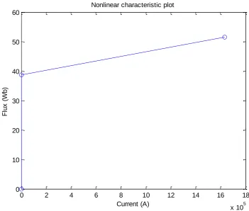
Traditionally, tuning of arc suppression coils was achieved by taps on the inductor winding. This made accurate tuning difficult to achieve. However, there have been significant developments in methods of automatically determining the system parameters [19] and automatic tuning systems [9-12]. These have become economic methods of enhancing the performance of arc suppression coil systems.
The advantages of keeping the system accurately tuned are:
The reduced fault current will minimise the damage caused.
The reduced fault current will increase occurrence of the extinction of the power follow arc following a lightning flash-over.
19 For these reasons the following analyses assume that the system is accurately tuned at the time of occurrence of the system abnormality.
4.2 Causes of abnormal neutral voltages
Three reasons for abnormal neutral voltages being generated in arc suppression coil systems that have been identified are:
A line to earth fault
Out of balance in the line to earth capacitance.
An open circuit in one phase line
4.2.1 A line to earth fault.
For low impedance line to earth faults the neutral voltage will be 1.0 pu. For high impedance line to earth faults the neutral voltage will be less than 1.0 pu.
4.2.2 Out of balance in the line to earth capacitance.
An out of balance in the line to earth capacitances will cause a neutral voltage because of the out of balance capacitive current flowing through the arc suppression coil. Out of balance capacitances can be caused by the placement of conductors on the structures, by single phase spur lines, or by some sudden system abnormality. In most distribution systems it would be expected that the out of balance capacitance would be small. In transmission lines the normal phase transposition of the
conductors would reduce the imbalance in the line to earth capacitance. Any sudden change in the out of balance capacitance which does not coincide with planned switching could indicate a system abnormality.
4.2.3 An open circuit in one phase line
It is shown that when there is an open circuit in one phase with significant load connected on the load side of the open circuit, the neutral voltage can exceed 1.0 pu. The lack of immediate recognition of this type of event has led to severe over-voltages and equipment damage [33].
4.3 A line to earth fault
20 Figure 4.5 Neutral voltage for a simulated single line to earth fault varying from zero to 1 MΩ, and with faults on each phase line in turn. The reference phase
angle is A to N.
21 A typical urban zone substation 11 kV network as shown in Figure 4.6 was then modelled using EMTP. As evaluated in Appendix A2, the distribution transformers connected to the system also contribute some zero sequence capacitance. A single line to earth fault was simulated on various places in the network. The results obtained with the EMTP analysis were similar to those shown in Figure 4.5.
7 km 2 km 1 km 1 km
7 km
5 km
7 km
1 km
2 km
3 km
7 km
1 km
1km
2 km
1 km
7 km
100 MVA
11 kV Busbar
Figure 4.6 Urban Zone substation area 11 kV network.
It can be seen that the neutral voltage magnitude is never greater than 1 pu and the phase angle is close to 600, 1800 or -600 depending on the which phase line is affected. This is to be expected as the tuned circuit with some losses would behave as a resistance. Because of the effect of the line reactance there is a small change in phase of the voltage for faults with significant impedance.
4.4 A disturbance in the line to earth capacitance balance.
22 Using the simple system shown in Figure 4.1, a change in line to earth capacitance in one phase was simulated. The symmetrical component network can then be
represented as shown in Figure 4.7, where the change in line to earth capacitance in one phase is represented byC0. This is in accordance with the symmetrical component representation of an out of balance capacitance shown in [63]. An increase on the capacitance to earth in one phase would be represented by an increase in C0and a decrease on the capacitance to earth in one phase would be represented by decrease or a negative value for 0
C
. Where there is a decrease in the capacitance to earth in two phases the effect is represented by a decrease in the zero sequence capacitance and an increase in C0.
LL
3LC
Positive Sequence
Negative Sequence
Zero Sequence
3RCΔC0
/3
RL
LL
LL
RL
RL
CL/2
CL/2
CL/2
CL/2
CL/2
CL/2 3RCE
+
+
+
+
-0
0 0
0 VS
+
Figure 4.7 Symmetrical component network for the simple system with an out of balance line to earth capacitance.
The neutral voltage was calculated for values of C0 varying between plus and minus 10% of 0
L
23 Figure 4.8 Neutral voltage for a simulated out of balance capacitance varying
from plus 10% ofCL0 to minus 10% ofCL0on each phase line in turn. The reference phase angle is A to N.
The voltages for several out of balance capacitance conditions were checked using the EMPT software and the resulting neutral voltages were almost identical to those shown in Figure 4.8.
Using EMTP software the out of balance capacitances were also checked for the more representative urban zone substation network shown in Figure 4.6 with out of balance capacitances introduced at various points in the system in turn. The results were similar to those shown in Figure 4.8.
It can be seen that the neutral voltage does not have a magnitude of greater than 1 p.u, and that the voltage does not have a phase angle of 600, 1800 or -600 for any of these out of balance conditions. On the basis of the phase angle we can distinguish between an out of balance capacitance condition and a line to earth fault.
24
C
LV
S3L
CΔC
0/3
+ 03R
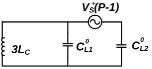
CLFigure 4.9 Symmetrical component network for the simple system with the line impedances ignored, the arc suppression coil losses represented by a single
resistor and out of balance line to earth capacitance.
As the admittance of the coil and that of the zero sequence capacitance add to zero, we have the classic case of a capacitance in series with a resistance. The voltages across the resistor and the capacitor will always be displaced by 900.
The plot as C0 is varied will then be part of a circle as shown in Figure 4.10 where
VR and VC represent the voltages across 3RCLand
0
/ 3
C
respectively.
Real component of neutral voltage, pu
Im a g in a ry c o m p o n e n t o f n e u tr a l v o lt a g e , p u 0 -0.5 -1.0 0 -0.5 +0.5 VR VC
Figure 4.10 Neutral voltage for the simple system with the line impedances ignored, the arc suppression coil losses represented by a single resistor and out of balance capacitance varying from zero to infinity. The reference phase angle
is A to N. 4.5 An open circuit
25 The effects of distributed generation need to be considered in many cases. Both single phase and three phase distributed generation installations are becoming more common.
4.5.1 An open circuit in one phase with no earth fault
The simple system as shown in Figure 4.1 was used to analyse the effect of an open circuit in one conductor with no earth fault.
Using the method given in [53], the system can be represented by symmetrical components, as shown in Figure 4.11, where the subscripts “M” and “N” refer to the sections of the network on the supply side and on the load side of the open circuit respectively. RLd and RLd refer the positive and negative sequence resistances representing a 100 kW delta connected load.
Zero sequence Negative sequence
Positive sequence
R
LM0
L
LM0 _
L
LM+
R
LM+
_
+
_
0 0
+ +
_ _
C
LM/2
0
V
S+3L
C3R
CC
LM/2
R
LNL
LN+
R
LMR
LN_
L
LML
LNC
LN/2
C
LM/2
C
LN/2
C
LN/2
0
R
LNL
LNR
LdR
Ld+
_
3R
CE26 This system was analysed for an open circuit with the proportion of the network on the source side of the open circuit varying continuously from 0% to 100% and on each phase line in turn. The resulting neutral voltages were plotted as shown in Figure 4.12.
Figure 4.12 Neutral voltage for a simulated open circuit on each phase line in turn, with the proportion of the network on the load side of the open circuit varying continuously from 0% to 100% and with 100 kW of connected load on
the load side. The reference phase angle is A to N.
It can be seen that depending on the position of the open circuit the neutral voltage can be higher than 1 pu. The phase angle is very close to 900, -1500 or -300
depending on which phase line is affected.
For several values the results were confirmed with EMTP software using the both the simple system model of Figure 4.1, and an urban zone substation model, as shown in Figure 4.6.
A clearer understanding of the issue may be gained by considering a simplified system with line inductances and all losses ignored.
27
C
LMV
S3L
CC
LN+
0 0
R
Ld+R
Ld-Figure 4.13 Sequence network of the simple system with an open circuit in one conductor and with line inductances and all losses ignored.
LetYC0 be the zero sequence admittance of the arc suppression coil.
Let 0
LM
Y be the zero sequence admittance of the capacitance to earth of the network on the source side of the open circuit.
Let YLN0 be the zero sequence admittance of the capacitance to earth of the network on the load side of open circuit.
If the arc suppression coil is correctly tuned to the line to earth capacitances then the sum of the admittances will be zero. Therefore:
0 0 0
0
C LM LN
Y Y Y (4.4)
0 0 0
C LM LN
Y Y Y (4.5)
28
0
0 0 0
1 1 1 1 1 S Ld Ld
C LM LN
V I
R
R
Y Y Y
(4.6)
However the impedance of the zero sequence branch is given by:
0
0 0 0
1 1
0
C LM LN
Z
Y Y Y
(4.7)
Therefore RLd can be ignored and:
0 S Ld V I R (4.8)
The zero sequence current is limited only by the impedance of the connected load and:
0 0
1
S n
Ld C LM
V V
R Y Y
(4.9)
From (4.5) and (4.9) we get:
0 S n Ld LN V V R Y
(4.10)
Equation (4.10) explains the + 900 phase shift of the neutral voltage for an open circuit in A phase, as shown in Figure 4.12.
4.5.2 The effect of distributed generation.
29 A C B a n b c
Delta-Star Transformer Load
Figure 4.14 Delta-star connected transformer with an open circuit in one line. The inverters connected to the affected low voltage phase lines will shut down on under voltage.
The remaining inverters will be injecting power in single phase mode between the two intact high voltage lines. These will not significantly affect the neutral voltage because the zero sequence network is not affected. In situations where there is three phase distributed generation, there may be a positive sequence voltage source on the load side of open circuit. As shown in Figure 4.15, and Figure 4.16, the isolated generation voltage source, VI, will be in parallel with the load impedance, RLd .
Zero sequence Negative sequence Positive sequence RLM 0 LLM 0 _ LLM + RLM + _ + _ 0 0 + + _ _
CLM/2
0
VS+
3LC
3RC
CLM/2
RLN LLN
+
RLM RLN
_
LLM LLN
CLN/2
CLM/2 CLN/2
CLN/2
0
RLN LLN
RLd RLd + _ 3RCE VI +
30 CLM
VS
3LC
CLN
+
0 0
RLd+
RLd
-VI +
Figure 4.16 Sequence network for the simple system with an open circuit in one conductor, with line inductances and all losses ignored and with isolated three
phase generation on the load side.
If the distributed generation is in phase with the main source it will cause a reduction in the neutral voltage with no change in phase angle. Because it is likely to be
slightly out of phase, distributed generation will cause a reduction in the magnitude of the neutral voltage together with a small change in phase angle. Networks with isolated three phase generation would need detailed analysis.
The above conclusions for isolated generation have been proven using EMTP simulations with the system represented as shown in Figure 4.17. The arc
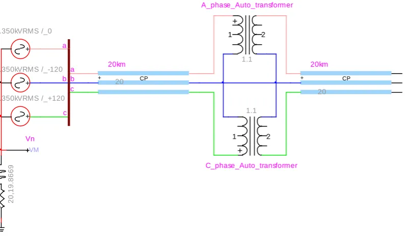
suppression coil is represented by an ideal inductor of 15.8935 Henries, a resistor of 24,9650 ohms to represent the energising equivalent resistance and a resistor of 99.8619 ohms to represent the equivalent coil resistance. The three phase infinite source is represented by three ideal generators with the output phase angles displaced by 1200 from each other. The 50 km 11 kV overhead line with an open circuited conductor at the mid-point is represented by two 25 km lines with two phases
connected and the third connected through an open switch. The isolated generation is represented by three delta connected ideal generators in series with suitable
31 Figure 4.17 EMTP representation of an open circuit in one phase line and
isolated generation. 4.5.3 Open circuit with a line to earth fault
32 Zero sequence
Positive sequence
RLM
0
LLM0
_ LLM + RLM + _ + _
CLM/2
0
VS
+
3LC 3RC
CLM/2
RLM LLM CLM/2
3RCE + _ 0 0 + _
RLN LLN
+
RLN
_
LLN CLN/2
CLN/2
CLN/2
0
RLN LLN
RLd RLd + _ 3RFN 3RFM Negative sequence
Figure 4.18 Sequence network for the simple system with an open circuit and simultaneous single line to earth faults at the same location and in the same
conductor.
This system was analysed for open circuits at three locations in turn for a range of fault resistances, continuously varying from zero to1 MΩ, on either side of the open circuit, and on each phase line in turn. The resulting neutral voltages were plotted as shown in Figures 4.19 and 4.20.
33
Figure 4.19 Neutral voltage for an open circuit at three locations, and a line to earth fault at the same location on the load side varying from zero to 1 MΩ, and
35 4.6 Appropriate actions to take on detecting an abnormal neutral voltage. When an abnormal neutral voltage is detected there are several possible protective actions:
Bypass the arc suppression coil as shown in Figure 4.21.
Isolate the affected feeder
Isolate the whole system
Initiate a line patrol
A
B
C
a
b
c Supply transformer
Arc suppression coil Single pole
circuit breaker
Figure 4.21 Bypassing of arc suppression coil.
In the event of a low impedance earth fault which persists, there is a possibility that the fault could be of a type which can be cleared by bypassing the arc suppression coil so as to apply normal fault current and allowing conventional protection to clear the fault. These fault types include such things as a snake or vermin across an
insulator. In power systems fitted with line circuit breakers, reclosers, or
36 For example consider the following hypothetical scenario:
A vehicle has collided with a pole and as a result a conductor, while not being broken, has become free from its insulator. There is now a conductive path to the vehicle. The situation is such that, while the bypass switch is open and the fault current is almost zero the voltage being applied to the vehicle is minimal. When the bypass switch is closed high voltage is applied to the vehicle.
In this scenario, closing the bypass switch could cause the death or serious injury to an occupant or to another person trying to help.
The dilemma, for the network operator, is to set a policy for the particular geographic area. The data to be considered in setting a policy may include such factors as history of faults, proximity to populated areas, and so on.
A high impedance earth fault which persists could be due to a tree making contact with the line, an insulating component beginning to fail, or it could be due to a more serious event. In this case, the network operator may decide that it is appropriate to leave the line energised and patrol the line using visual, radio interference, thermal imaging, corona discharge, or other techniques.
In the event of an open circuit combined with an earth fault in an overhead system, it may be concluded that a conductor has broken and fallen. An open circuited bridge with an earth fault would seem unlikely. In the event of an open circuit without an earth fault, it could be a broken bridge, a broken conductor with the ends clear of the earth, or the fallen end insulated from the earth by vehicle tyres or other means. This is a situation which could result in death or serious injury. On this basis, it may be decided that any open circuit should be treated as a dangerous situation and the relevant line disconnected from supply immediately.
In the event of a disturbance in capacitive balance without an open circuit, the
probable causes would appear to be limited to less likely events such as a fault in star connected capacitor bank. In the absence of star connected capacitor banks on the system, it may be decided that if there is a disturbance in the capacitive balance there may be a dangerous situation and the relevant line should be disconnected from the supply immediately.
37 In cases where it is decided to disconnect the line from supply, it may be possible to determine the location of the fault based on one of the methods recently developed [21-27] so that only the affected line is isolated. It is worth noting that in the unlikely event of a turn to earth fault within the secondary winding of the star connected supply transformer the neutral voltage will appear the same as for a high impedance line to earth fault. Although this is not a dangerous situation, it is one that should be rectified as quickly as possible. For an internal fault, where there is arcing or high temperatures in one spot, the buchholz relay should initiate a trip. The methods of locating a permanent fault previously mentioned may be useful in eliminating a feeder fault as the cause.
4.7 Evaluation of fault and appropriate actions
By analysing the magnitude and phase angle of the neutral voltage when a fault occurs, it is possible to make some determinations about the type of fault. From an examination of the neutral voltages for various types given in Figures 4.5, 4.8, 4.12, 4.19 and 4.20, it can be seen that the possible faults for each voltage configuration are as shown in Figure 4.22.
In Figure 4.22, it is important to note that the types of faults shown are possible faults. Figure 4.22 can best be understood by following the logic forward and backwards from each possible fault type. While in many cases the fault type can be determined precisely, there are some cases where it can only be narrowed down to two alternatives. For example, it is not possible to distinguish between a low impedance line to earth fault without an open circuit, and a low impedance line to earth fault on the source side of an open circuit. Similarly, a change in line to earth capacitance on one phase cannot always be distinguished from an open circuit with a line to earth fault. Provided the consequent actions to be taken are the same for the indistinguishable types of faults, then this is not a serious impediment. On the other hand, one can categorically state that if the neutral voltage is greater than 1 pu there is an open circuit.
If it is decided to bypass the arc suppression coil in the event of a low impedance fault, the criteria for determining the critical value for a „low‟ impedance fault would take into account the sensitivity of the conventional earth fault protection. There is no point in bypassing the arc suppression coil for faults that cannot be detected by the conventional protection. Therefore, the criteria for determining the critical value for “close to 1 pu”, may be based on the sensitivity of the conventional earth fault protection.
38 Simultaneous open circuit and line to earth faults are considered to be affecting the same phase line. The incidence of an open circuit in one phase line and a earth fault in another phase line as a result of the same event would appear to be rare.
Magnitude of neutral voltage Phase angle of neutral voltage
Less than 1 pu
Close to 1 pu
Greater than 1 pu
Close to 600 ,1800 or -600 Close to 900 ,-1500
or -300
YES YES YES YES NO YES NO
Low impedance line to earth
fault
High impedance line to earth
fault
AND
Open circuit without a line to earth fault
Open circuit with a low impedance load side line to
earth fault AND AND OR AND AND By-pass arc suppression coil and allow conventional protection to operate. Disconnect the affected line. Open circuit
with a line to earth fault Patrol the affected line. Possible faults Actions to be taken Neutral Voltage Change in capacitance to
earth of one phase of up to plus or minus
10% Open circuit with a low impedance supply side line to earth fault
OR OR
Figure 4.22 Possible fault types and appropriate actions deduced from the neutral voltage.
Automatic whole of substation or system protection equipment, such as that described in [44-46], will be able to take appropriate action immediately on the basis of the neutral voltage using the criteria shown in Figure 4.22.
The actions to follow would depend on the policy adopted by the network company. Those shown in Figure 4.22 are based on one reasonable company policy.
39
Magnitude of neutral voltage Phase angle of neutral voltage
Less than 1 pu
Close to 1 pu
Greater than 1 pu
Close to 600,1800 or
-600
YES YES YES YES NO
OR AND
AND
By-pass arc suppression coil
and allow conventional protection to
operate. Patrol the
affected line.
Disconnect the affected line
Figure 4.23 Logic for taking action on the basis of the neutral voltage. It is envisaged that the protection control computer would display and record the possible types of faults as set out in Figure 4.22, but initiate actions based on the logic of Figure 4.23
4.8 Summary
40 By monitoring both the phase angle and the magnitude of the neutral voltage, it is possible to automatically diagnose many abnormal conditions on the power system to the extent that decisions can be made on the appropriate action to take.
In at least one country, automatic computerised substation and whole of system protection systems are currently being installed in lieu of individual numeric relays [44-46].
41
Chapter 5
IN-LINE VOLTAGE REGULATORS
For arc suppression coil systems to be used in high voltage distribution systems it is necessary for the in-line voltage regulators used to be compatible with their
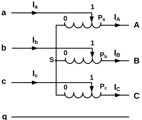
operation. If the regulators provide an alternate electrical path to earth or inhibit the flow of zero sequence currents along the line the arc suppression coil systems will not operate effectively. It is also important that the in-line voltage regulators do not introduce a zero sequence voltage in series with the line because this can cause very high voltages under normal operating conditions. In this chapter these issues are examined in detail and a practical method of providing in-line voltage regulation is proposed. It is also noted that the number of in-line voltage regulators in the system may be economically reduced by installing distributed static VAR compensators using a control scheme such as that described in [65].
5.1 Open-delta regulators
The use of two auto-transformers connected in open-delta to regulate the voltage in three phase high voltage distribution systems has now become common practice, in systems with the neutral of the zone substation transformer effectively earthed, because of cost savings.
A new generalized sequence network representation of a system with open-delta regulators has been developed. This representation provides a tool to calculate the voltages which may occur in proposed power systems. Previous detailed analyses of open-delta voltage regulators did not use symmetrical components [47-49].
An open-delta regulator consists of two auto-transformers connected as shown in Figure 5.1.
Va
Vc Vb
VA VB
VC Ib
Ia
Ic
IB
IA
IC
Primary
Side
Secondary
Side
Vg Vg
42 Two auto-transformers can conveniently be mounted on a single pole as shown in Figure 5.2
Figure 5.2 Pole mounted open-delta regulator.
43
V
AV
aV
bV
CV
cV
BFigure 5.3 Voltage phasor diagram for an open-delta regulator. Let the transformation ratio be P such that:
BA ba
V PV (5.1)
and:
CA ca
V PV (5.2)
For ideal open-delta connected auto-transformers the voltage and current relationships can be expressed as follows;
Ag ag
V V (5.3)
( 1)
Bg bg ba
V V P V (5.4)
( 1)
Cg cg ca
V V P V (5.5)
b B
44
c C
I PI (5.7)
( 1) ( 1)
a A B C
I I P I P I (5.8)
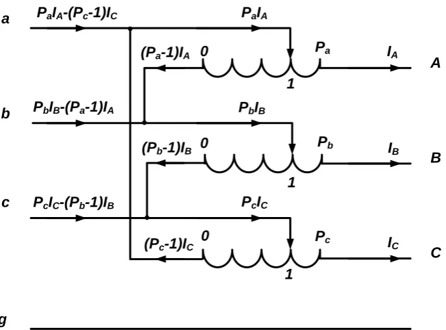
5.1.1 Modelling of open-delta regulators using symmetrical components To analyse the neutral voltages and currents in circuits containing open-delta regulators it is appropriate to use symmetrical components.
Let VS,VS and VS0 be the positive, negative and zero sequence secondary voltag