DEVELOPMENT OF FOUR WHEEL STEERING SYSTEM FOR RC VEHICLE
MOHD HANIF BIN MD YUSUF
This report is submitted to Faculty of Mechanical Engineering as partial requirements for the degree of Bachelor of Mechanical Engineering (Automotive)
Faculty of Mechanical Engineering Universiti Teknikal Malaysia Melaka
ii
COMFORMATION
I admit that have read this work and in my opinion this work was adequate from scope aspect and quality to award in purpose Bachelor of Mechanical Engineering
(Automotive)
Signature :……… 1st Supervisor’s name:……… Date :………
iii
DECLARATION
“I hereby, declare this thesis entitled Development of Four Wheel Steering System for RC Vehicle is the result of my own research except as cited in the reference”
Signature :………
iv
DEDICATION
To my beloved father, Md Yusuf B Ithnain And to my beloved mother,
Faridah Bt Sulaiman
v
ACKNOWLEDGEMENT
I would like to take this opportunity to thank to Allah S.W.T. with all His Gracious and His Merciful for giving me strength and ability, to finish my final year project. By this chance, I would like to express my deepest gratitude to Dr. Khisbullah Hudha for his kind effort in guiding me to perform the project procedure and lending his hand for supporting me in my project accomplishment.
I also want to give my thankful greeting to Mr. Ubaidillah, and Mr. Fithrian, who also the Master’s students in the Mechanical Engineering Department for giving me guidance and cooperation to assist in achieving my project objectives. The other appreciation also favors to the other Master’s students those were helping me indirectly and always welcoming me to ask question.
vi
ABSTRACT
vii
ABSTRAK
viii
TABLE OF CONTENT
CHAPTER TITLE PAGES
DECLARATION iii
DEDICATION iv
ACKNOWLEDGEMENT v
ABSTRACT vi
ABSTRAK vii
TABLE OF CONTENT viii
LIST OF TABLE xi
LIST OF FIGURE xii
LIST OF SYMBOL xvi
LIST OF APPENDIX xviii
CHAPTER 1 INTRODUCTION 1
1.1 Introduction 1
1.2 Objective 3
1.3 Scope 3
1.4 Problem Statement 3
CHAPTER 2 LITERATURE REVIEW 5
2.1 Steering system 5
2.2 Type of Steering System 7
2.2.1 Four Wheel Steering (4WS) 7
2.2.2 Manual steering 8
ix
CHAPTER TITLE PAGES
2.2.2.2 Rack and pinion steering 10
2.2.3 Power Steering 11
2.2.4 SuperSteer 12
2.2.5 Steer-By-Wire 13
2.2.6 Speed Adjustable Steering 15
2.2.7 Quadrasteer 15
2.2.8 Articulated steering 16
2.3 RC Model 17
2.3.1 Ackerman Angle 17
2.3.2 4WS System 19
2.3.3 RC Geometry 21
2.3.4 RC Design 22
2.4 Testing of Handling Characteristics 24 2.4.1 Constant Forward Speed Test 24
2.4.1.1 Double Lane Change Maneuver
24
2.4.1.2 Single Lane Change Maneuver
26
2.4.2 Constant Radius Test 27
2.4.3 Slalom Test 27
CHAPTER 3 METHODOLOGY 28
3.1 Flowchart 28
3.1.1 Project Overview 28
3.1.2 Problem Identification 30
3.1.3 Data collection 30
3.1.4 Analysis activity 30
3.1.5 Model making and testing 31
3.1.6 Discussion and progress report 32
x
3.2.1 Equipments 33
3.3 Result variable 36
3.4 Experiment procedure 37
CHAPTER 4 RESULT AND DISCUSSION 41
4.1 Mathematical modeling 41
4.2 Simulation Studies 44
4.2.1 Conditions for the simulations 44
4.3 Control Structure 46
4.4 Result discussion 47
4.4.1 Simulation result 47
4.4.2 Experiment result 51
4.4.3 Result Validation 54
CHAPTER 5 CONCLUSION AND FUTURE WORK 56
5.1 Conclusion 56
5.2 Future Work 58
REFERENCES 59
BIBLIOGRAPHY 62
xi
LIST OF TABLE
NO. TITLE PAGES
4.1 Vehicle Parameters 45
4.2 Final test result 54
5.1 Advantages for the 2WS and 4WS 55
xii
LIST OF FIGURE
NO. TITLE PAGES
1.1 Steering system diagram (Basic structure, 2000) 1
2.1 Vehicle six degree of freedom (Wong, 2001) 6
2.2 Rear wheels are turned in opposite direction of front wheels (Four Wheel Steering System, 2009)
7
2.3 All four wheels are turned in same direction (Four Wheel Steering System, 2009)
8
2.4 Typical recirculating ball steering system (Nice, Recirculating ball steering, 2009)
9
2.5 Rough diagram of a Recirculating Ball steering mechanism (Nice, Recirculating ball steering, 2009)
10
2.6 Typical rack and pinion steering gear, used on most of today’s passenger vehicles (Rack and Pinion, 2009)
10
2.7 Rack and pinion steering diagram (Nice, Rack and Pinion, 2009)
11
xiii
2.9 Tractor using the super steer steering system (Super Steer, 2009)
13
2.10 Steer-by-wire mechanical system (Lorincz, 2004) 14
2.11 Quadrasteer Steering System (Cooney, 2003) 16
2.12 Hydraulic cylinders control the articulated steering (Articulated Steering, 2006)
17
2.13 Parallel steering arms
(Ackerman Steering Principle, 2009)
18
2.14 Effects of angled or Ackerman Steering (Ackerman Steering Principle, 2009)
18
2.15 Ways of steering the rear wheels (Brabec, P. et. al., 2004)
20
2.16 Comparison of the avoidance maneuver with a vehicle with 2WS (conventional steering) and 4WS
(Brabec, P. et. al., 2004)
20
2.17 Sample of vehicle model (Brabec, P. et. al., 2004) 21
2.18 Arrangement of the model 22
2.19 Component for the first design (Steering servo, 2008) 23
2.20 Design for the linkage between the front axle and rear axle (Steering servo, 2008)
23
xiv
2.22 Road path for real input to vehicle and analytic input (Orozco, 2004)
26
2.23 Single lane change test (Professor Will, 2000) 26
2.24 Straight slalom test 27
3.1 Flow Chart for the whole PSM 29
3.2 The linkages and servo that want to test to determine the durability and it can work properly
32
3.3 Flour on the surface of the testing area with the starting grid
33
3.4 Remote control car model (Scale 1: 10 from the actual size vehicle)
34
3.5 Steering servo and the linkages 34
3.6 Servo with the modified wiring 35
3.7 Suspension system and wheel 35
3.8 The initial testing 36
3.9 The experiment flow for the J-Turn Test 38
3.10 The experiment flow for the Circle Test 39
3.11 The experiment flow for the Slalom Test 40
xv
4.2 Main system for single model 46
4.3 Control structure in the main model 46
4.4 Graph of vehicle sideslip angle versus time (single lane-low speed)
47
4.5 Graph of vehicle sideslip angle versus time (single lane-high speed)
48
4.6 Graph of vehicle sideslip angle versus time (double lane-low speed)
49
4.7 Graph of vehicle sideslip angle versus time (double lane-high speed)
50
4.8 Result for J-Turn Test 51
4.9 Result for Circle Test 52
4.10 Result for Slalom Test (1m pole to pole) 53
4.11 Result for Slalom Test for 4WS (0.75 m between poles) 53
xvi
LIST OF SYMBOL
D∅ = Roll axis damping, Nm/rad K∅ = Roll axis stiffness, Nm/rad
∅ = Vehicle roll angle, rad
Cf = Front cornering stiffness, N/rad
Cr = Rear cornering stiffness, N/rad
Fxij = Tire longitudinal force, N
Fyij = Lateral force, N
G = Gravity acceleration, ms-2
hs = Distance of the sprung mass c.g. from the roll axes, m
Ixx = Moment of inertia about roll axis, kg m2
Ixz = Sprung mass product of inertia, kg m2
Izz = Moment of inertia about yaw axis, kg m2
Lf = Distance from c.g. to front axle, m
Lr = Distance from c.g. to rear axle, m
m = Vehicle total mass, kg ms = Vehicle sprung mass, kg
Tf = Front track width, m
Tr = Rear track width, m
u = Longitudinal velocity, ms-1 v = Lateral velocity, ms-1 Xij = Longitudinal tire force, N
Yij = Lateral tire force, N
αf = Front wheel slip angle, rad
αr = Rearwheel slip angle, rad
xvii
δf = Front wheel steering angle, rad
xviii
LIST OF APPENDIX
NO. TITLE PAGES
A Gantt Chart for PSM 1 and PSM 2 63
B Steering Configuration Figures 64
C Rear Wheel Linkages, Measuring procedure and RC vehicle drifting
1
CHAPTER 1
INTRODUCTION
[image:19.612.207.449.349.561.2]1.1 Introduction
Figure 1.1: Steering system diagram (Basic structure, 2000).
2
In Figure 1.1, the steering system was build by the combination from a few components that help driver with the handling maneuver. The components are, : 1) steering wheel; (2) steering shaft; (3) intermediate shaft; (4) steering gear assembly; (5) pressure hose; (6) return hose; (7) oil pump; (8) solenoid valve; (9) ECU; (10) reserve tank; (11) steering angle sensor; (12) check connector.
A steering aid system called active steering is evaluated by simulating different driving events. The active steering solution, which is taken from a scientific paper, has been implemented in MATLAB. The input to the vehicle model is the steering wheel angle performed by the driver/ controller. Simulations are made by using constant speed as a reference and a specific changeable road adhesion coefficient as an input.
The control system takes the slip angle as input and derives a steering angle contribution to be added to the drivers command. The motivation for this work is to understand and characterize the response of a vehicle with a complementary steering system. Specific driving events are considered for the simulations such as a wind force disturbance and a severe double lane change.
The response of the controlled vehicle is similar to the response of the conventional vehicle for nominal driving, but the steering aid system reduces the effect of wind force disturbances. Improved stability is obtained for the vehicle during slippery road driving.
3
the simulation and the comparison will be discussed to determine if the experimental result follow the simulation data to prove that the 4WS is better than the 2WS vehicle.
1.2 Objectives
There are two objectives need to be achieved by the end of the semester which are: i. To develop an active control of four wheel steering system on RC vehicle.
ii. To analytically study the advantages of additional rear wheel steering system in reducing the turning radius during maneuver.
1.3 Scope
The main scopes for this project are:
i. Deriving mathematical model of four wheel steering system.
ii. To modify the existing Forward Wheel Steering (FWS) of RC vehicle into 4 Wheel Steering (4WS) systems.
iii. Simulation studies on the controller design of 4WS system by using the MATLAB Simulink.
1.4 Problem Statement
4
system car. So, this project is base on how to prove that the 4WS is better than 2WS through Simulink and experimental result.
5
CHAPTER 2
LITERATURE REVIEW
Literature review is the initial step to collect all the information and data about the topic that for this research, and from the information gathered, it will be analyze and the experiment testing will be done according to the journal or research, to get the real result from the real situation. When gathering the information about this topic, several sources have been used, such as journal, references book, website and other source regarding to the research topic from the already made product as guidance to learn more about the topic for this project. Therefore, this initial stage is very important to learn more the topics, to get know the problems arise and how to solve it before doing the simulation and experiment procedures.
2.1 Steering system
6
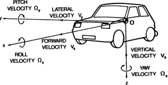
[image:24.612.185.475.261.409.2]The vehicle as a rigid body has six degrees of freedom, translations along the x, y and z-axis, and rotations about this axis shown in Fig.2.1. The primary motions due to the handling behavior of a vehicle are longitudinal, lateral, and yaw motion. During turning maneuver, the vehicle body rolls about the x- axis. This roll motion may cause the wheels to steer, thus affecting the handling behavior of the vehicle. Furthermore, bounce and pitch motions of the vehicle body, may also affect the steering response of the vehicle. However, the inclusion of these motions only become necessary in the analysis when considering the limits of handling characteristics (Wong, 2001).
Figure 2.1: Vehicle six degree of freedom (Wong, 2001).
Simplified linear model for the handling behavior of passenger car in which suspension characteristics are not taken into account will be discussed. The model demonstrate the effects on handling behavior of major vehicle design and operational parameters, such as tire properties, location of the center gravity, and forward speed and lead to conclusions of practical significance concerning directional control and stability. The response of the vehicle to steering input and its directional stability associated with a fixed steering wheel, which are usually referred as fixed control- characteristics will be analyzed (Wong, 2001).