UNIVERSITI TEKNIKAL MALAYSIA MELAKA
DEVELOPMENT OF MOULD TO FABRICATE ALUMINA CUTTING TOOL BY USING 3D PRINTER TECHNOLOGY WITH ABS AND PLA MATERIAL
This report is submitted in accordance with requirement of the Universiti Teknikal Malaysia Melaka (UTeM) for the Bachelor Degree of Manufacturing Engineering (Hons)
by
MOHAMAD RUSYDI AZIM BIN MOHAMAD SATTAR B051510024
940916-06-5251
UNIVERSITI TEKNIKAL MALAYSIA MELAKA
BORANG PENGESAHAN STATUS LAPORAN PROJEK SARJANA MUDA
Tajuk: DEVELOPMENT OF MOULD TO FABRICATE ALUMINA CUTTING TOOL BY USING 3D PRINTER TECHNOLOGY WITH ABS AND PLA
MATERIAL
Sesi Pengajian: 2017/2018 Semester 2
Saya MOHAMAD RUSYDI AZIM BIN MOHAMAD SATTAR (940916-06-5251)
mengaku membenarkan Laporan Projek Sarjana Muda (PSM) ini disimpan di Perpustakaan Universiti Teknikal Malaysia Melaka (UTeM) dengan syarat-syarat kegunaan seperti berikut:
1. Laporan PSM adalah hak milik Universiti Teknikal Malaysia Melaka dan penulis. 2. Perpustakaan Universiti Teknikal Malaysia Melaka dibenarkan membuat
salinan untuk tujuan pengajian sahaja dengan izin penulis.
3. Perpustakaan dibenarkan membuat salinan laporan PSM ini sebagai bahan pertukaran antara institusi pengajian tinggi.
4. *Sila tandakan (√)
SULIT (Mengandungi maklumat yang berdarjah keselamatan atau kepentingan Malaysia sebagaimana yang termaktub dalam AKTA RAHSIA RASMI 1972)
TERHAD (Mengandungi maklumat TERHAD yang telah ditentukan oleh organisasi/ badan di mana penyelidikan dijalankan)
TIDAK TERHAD
Disahkan oleh:
Alamat Alamat Tetap: Cop Rasmi:
Tarikh: Tarikh:
*Jika Laporan PSM ini SULIT atau TERHAD, sila lampirkan surat daripada pihak
berkuasa/organisasi berkenaan dengan menyatakan sekali sebab dan tempoh laporan PSM ini perlu
dikelaskan sebagai SULIT atau TERHAD.
DECLARATION
I hereby, declared this report entitled “Development of mould to fabricate alumina cutting tool by using 3D printer technology with Abs and Pla material” is the results of my own
research except as cited in reference.
Signature :……….
Author’s Name : MOHAMAD RUSYDI AZIM BIN MOHAMAD SATTAR
APPROVAL
This report is submitted to the Faculty of Manufacturing Engineering of Universiti Teknikal Malaysia Melaka as a partial fulfilment of the requirements for the degree
of Bachelor of Manufacturing Engineering (Hons.).
The members of the supervisory committee are as follows:
………
Prof Madya Dr IR Mohd Hadzley Bin Abu Bakar
i
ABSTRAK
ii
ABSTRACT
iii
DEDICATION
iv
ACKNOWLEDGEMENT
In the name of Allah, the Most Gracious and the Most Merciful.
Alhamdulillah, all praises to Allah for the strengths and His blessing in completing this project. Special appreciation goes to PM DR. IR. Mohd Hadzley Bin Abu Bakar my supervisor, for his supervision and constant support. His invaluable help of constructive comments and suggestions throughout the experimental and thesis works have contributed to the success of this research.
I would like to express my appreciation to all the technicians and office staffs of Faculty of Manufacturing Engineering UTeM for their cooperation’s.
v
TABLE OF CONTENTS
Abstrak i
Abstract ii
Dedication iii
Acknowledgement iv
Table of contents v-viii
List of Tables ix
List of Figures x-xi
List of Abbreviations xii
CHAPTER 1: INTRODUCTION
1.1 Project Background 1-2
1.2 Problem Statement 3
1.3 Objective 3
1.4 Scope of study 3-4
CHAPTER 2: LITERATURE REVIEW
2.1 Cutting Tool 5
2.1.1 Cutting Tool Geometry 6-7
2.2.2 Shape and Size of Cutting Tool 7
2.1.3 Ceramic Cutting Tool 7-8
2.1.4 Alumina-based Ceramic Cutting Tool 9
2.1.5 Alumina 10
2.1.6 Zirconia 11-12
2.1.7 Cold Isostatic Press (CIP) 12-15
2.2 Turning Machine 15
2.2.1 Background of Turning Machine 15-16
2.2.2 Types of Turning Machine 16
vi
2.2.2.2 Turning 16
2.2.2.3 Drilling 17
2.2.2.4 Reaming 17
2.2.2.5 Knurling 17
2.3 3D Printing 17-19
2.3.1 A Brief History of 3D Printing 19-20
2.3.2 Types of 3D Printing 21
2.3.2.1 Stereolithography (SLA) 21
2.3.2.2 Digital Light Processing (DLP) 21 2.3.2.3 Fused Deposition Modeling (FDM) 22 2.3.2.4 Selective Laser Sintering (SLS) 22-23
2.3.3 Process of 3D Printing 23-24
2.3.4 Advantage of 3D Printing 24
2.4 Acrylonitrile Butadiene Styrene 24-27 2.4.1 Advantage of Acrylonitrile Butadiene Styrene 27-28
2.5 Poly Lactic Acid 28-30
2.5.1 Advantage of Poly Lactic Acid 30-31
2.6 Mould 31-32
2.6.1 Plastic mould 32
2.6.1.1 Guide to Plastic Molding 33 2.6.1.2 Plastic Moulding Process 33-35 2.6.1.3 Plastic Mould Defects by 3D Printing Process 35-36
2.7 Summary 37
CHAPTER 3: METHODOLOGY
3.1 Introduction 38-39
3.2 Design 3D CAD Model 40
3.3 Preparation of Material 41-44
3.4 Fabrication of mould using the 3D printing 44-45
vii
3.4.2 Standard Operating Procedure (SOP) Up Plus 3D Printer 47-48
3.5 Polishing Process by Chemical Treatment 48-49
3.6 Testing Analysis for the mould 49-50
3.6.1 Stereo Microscope 50-51
3.6.2 Strength Test 51-52
3.6.3 Dimensional measurement and Shrinkage 52-53
3.7 Summary 53-54
CHAPTER 4: DESIGN, ANALYSIS AND RESULT OF MOULD WITH MATERIAL ABS AND PLA
4.1 Mould Design 55
4.2 Main part of the mould 55
4.2.1 Frame of the mould (Female) 56
4.2.2 Ejector (Male) 56-57
4.3 Design shape and material mould 57
4.3.1 Design shape 57-58
4.3.2 Mould material 59
4.3.2.1 Acrylonitrile butadine styrene (ABS) 59-60 4.3.2.2 Poly Lactic Acid (PLA) 60-61
4.4 Fabricating process 61-64
4.5 Final product 64-65
4.6 Analysis of mould 65-66
4.6.1 Strength test 66-67
4.6.2 Surface roughness 67-68
4.6.3 Microstructure 68-69
4.7 Conclusion of mould analysis of ABS and PLA mould 69-70
CHAPTER 5: CONCLUSION AND RECOMMENDATION FOR FURTHER WORK
5.1 Conclusion 71
viii
REFERENCES 73-74
ix
LIST OF TABLES
2.1 Mechanical properties of ceramic materials (Black and Kohser, 2008) 8
2.2 Properties of different alumina percentage 10
2.3 Properties of different zirconia percentage 12
2.4 Historical development of Rapid Prototyping and related Technology
(Source: http://www.worldscibooks.com) 20
2.5 Failure testing for 3D printed stage 25
2.6 Mechanical Properties ABS material 26
2.7 Mechanical Properties PLA material 29
3.1 Dimension of specimen part 40
3.2 Material properties of ABS 42
3.3 Material properties of PLA 44
3.4 Printer Physical Characteristic (Percoco, Lavecchia & Galantucci, 2012) 46
3.5 Environmental specification (Percoco, Lavecchia & Galantucci, 2012) 47
3.6 Specification of stereomicroscope 51
3.7 Specification of digital caliper 53
3.8 Summary of methodology used 54
4.1 List of fabrication process 63-64
4.2 Data strength test ABS mould 66
4.3 Data strength test PLA mould 67
x
LIST OF FIGURES
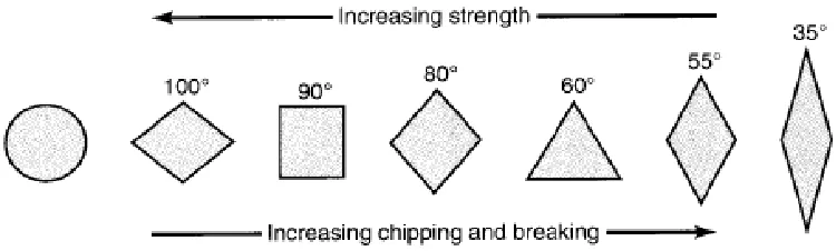
2.1 The arrangement of strength and tendency for various insert shape 7
(Source: Courtesy of Kennametal Inc.) 2.2 Structure of zirconia (Callister, 1996) 11 2.3 Comparison of density uniformity of product produced by (a) isostatic pressing (b) uniaxial pressing (Richerson, 2005) 14
2.4 Schematic of wet-bag isostatic pressing system (Richerson, 2005) 14
2.5 Schematic of dry-bag isostatic pressing system (Richerson, 2005) 15
2.6 Schematic of 3D printing process (Source: Mamivand et al, 2013) 19
2.7 Process of 3D printing (Kalpakjian & Schmid, 2006) 24
2.8 Acrylonitrile Butadiene Styrene (ABS) chain 26
(Shahir Hashim, Azman Hassan, 2010) 2.9 Poly Lactic chain 30 3.1 Process flow chart of the experiment 39
3.2 Geometry of 3D printed specimen 40
3.3 UP Plus 3D Printer (Percoco, Lavecchia & Galantucci, 2012) 45
3.4 Front view of UP Plus 3D Printer 45 3.5 Acetone 49
3.6 Stereo microscope 50
3.7 Rockwell hardness tester 52 3.8 Digital Caliper 53 4.1 Frame of the mould (Female) 56 4.2 Ejector (Male) 57 4.3 Steel mould design shape 58 4.4 ABS and PLA design shape 58
4.5 ABS Filament 60 4.6 PLA Filament 61 4.7 Flow chart fabricating process 62 4.8 ABS mould 65
4.9 PLA mould 65
4.10 Microstructure ABS 69
xi
LIST OF ABBREVIATIONS
2-D - 2 Dimensional
3-D - 3 Dimensional
ABS - Acrylonitrile Butadiene Styrene
CAD - Computer Aided Design
CAE - Computer Aided Engineering
CAM - Computer Aided Manufacturing
CATIA - Computer Aided Three-Dimensional Interactive Application
CNC - Computer Numerical Control
CIP - Cold Isostatic Press
FYP - Final Year Project
3DP - Three-Dimensional Printing
SLS - Selective Laser Sintering
UV - Ultra Violet
RP - Rapid Prototyping
SLA - Stereolithography
1
CHAPTER 1
INTRODUCTION
This chapter of introduction will presents and explains generally about the research of final year project. In which will provide a review of the project background, the problem statement, goal objectives, and also the scope of the research. Issues in this project will be explained and it will achieve distinguish of the objective of the research. The main of the this project is to figure out and investigate the development of mould for fabrication of alumina cutting tool by using 3D printing with ABS and PLA material.
1.1 Project Background
In industry, cutting tool is one of the most important parts. It can be consider as a major industrial prerequisite as it is function to apply mostly in parts production. The parts production in machining process has many shapes such as rectangular, square and round. It also has the nose radius such as straight, bent, cranked and round-nosed cutter and the cutting tool classes will follow according to the shapes given. The shaped of cutting tools was designed depended on the definite condition. Such as the material of the tools, the materials that need to be cut and also the process condition on the mechanical properties.
2
temperature and fast machining. Alumina based materials are among the most prevalent decisions to be utilized to manufacture cutting supplements since it has high hardness, high protection from scraped spot and concoction inactivity against the earth and the workpiece. Notwithstanding, the confinement of alumina based cutting additions is the low sturdiness of the pottery, which can cause chipping and breakage amid machining. Keeping in mind the end goal to conquer this issue, extra materials, for example, yttria balanced out zirconia, titanium carbide, silver and ceria are utilized to build the crack sturdiness of the alumina.
In making this cutting tool, must through some process. The cutting tool has many shapes according to the production parts given. To fabricate the cutting tools, it must have the main and fixed shape. A special mould is required to compact the powders to become a cutting tool. This research is mainly about the mould to fabricate the ceramic cutting tool. The mould is different than the conventional mould that mainly used in industry. The new idea of mould is more convenient and low cost. The new design of mould is by using the easy method than before this. Using the 3D printing to shape and act as a mould for the cutting tool. Furthermore, the mould was fabricated by ABS and PLA material. Which means the mould are easier to design and less cost than the conventional mould that use steel material.
The purpose of this project was to develop the mould to fabricate the ceramic cutting tool based on the specific composition of alumina powder. As the ceramic powders were compacted and sintered, the performance of ceramic cutting tool was evaluated based on wear performance and surface roughness of the machined surface. This project will evaluate the new development of mould based on the result of wear performance, surface roughness and strength test. In the end, this result will be used to propose some improvement and refinement for the development of mould to fabricate the cutting tool.
1.2 Problem Statement
3
diamond. These ceramic cutting tools has been widely known for their excellent performance in high speed and high temperature machining (Kalpakjian and Schmid, 2013). This is because the ceramics possess variety properties such as high hardness, high thermal shock resistance and high chemical stability. Besides, these cutting tool that produced in the industry are mainly using the mould that made by steel. The mould that using steel material is having a little bit problem. The problem where the process of fabricating it is high in tooling cost. The tooling to fabricate the cutting tool is using high cost tooling than can cause wastage to industry. The high tooling costs make this method uneconomical for little creation runs. Exactly when the technique is used to cast steel or iron the shape life is to an awesome degree short. For cut down melting point metals the frame life is longer however warm depletion and crumbling regularly control the life to 10,000 to 120,000 cycles. Besides, the current mould steel is complicated to fabricate it. There too many processes in making it. Furthermore, the mould is taking too much time to producing it while it can make it simpler. If considering on the material, it is hard to shape in making complex shape of mould. Also, the cost of material is high and expensive.
1.3 Objective
The objectives of this project are as follows:
i. To design a mould for alumina cutting tool by using 3D CATIA software.
ii. To fabricate a mould for alumina cutting tool by using 3D printing with ABS and PLA material.
iii. To evaluate the precision, surface roughness and strength of fabricated mould.
1.4 Scope of Study
4
5
CHAPTER 2
LITERATURE REVIEW
This chapter will discuss about the research of development of mould for fabrication of alumina cutting tool by using 3D printing with ABS and PLA material. In this part also will explain about cutting tool, turning machine, the material used for the mould, 3D printing, acetone for polishing and the main part is the mould. All the references are from the book, journal, conference paper, website and also article.
2.1 Cutting Tool
The choice of cutting device in metal cutting is exceptionally vital. An appropriate slicing device must be all around chose and reasonable to machine a given work material. Cutting instruments are available in an extensive variety of choice comprises of different properties, machining capabilities and costs. It has been demonstrated that parameters including cutting instruments, for example, apparatus geometry, device materials cutting parameters and have critical impacts on the profitability and execution of a machining operation (Black and Kohser, 2008).
2.1.1 Cutting Tool Geometry
6
side rake edge, side alleviation edge, back rake edge and back help edge. The points that have the hugest impact on apparatus life are the nose range, side rake edge and side front line.
(a) Rake angle
The most noteworthy capacity of the rake edge is to control the stream course of the chips and the apparatus tip quality. Positive rake angle can limit powers and temperature. Be that as it may, positive rake points may conceivably cause untimely apparatus chipping and inability to the cutting instrument with low toughness. (Kalpakjian, 2013)
(b) Side rake angle
The introduction of the rake confront is characterized by two edges which are side rake point and back rake edge. The last controls the stream heading of chips however side rake edge in more critical in machining. In metal cutting utilizing embeds, the point go are from - 5° to 5°. (Kalpakjian, 2013)
(c) Cutting edge angle
The cutting edge has huge impacts in the arrangement of chips, quality of the device, and cutting powers. The point of angle is often around 15°. (Kalpakjian, 2013)
(d) Relief angle
7
(e) Nose radius
The strength quality of the apparatus tip and surface complete can be influenced by the estimation of nose radius. A sharp device, which has little nose radius, creates harsh surface complete of the workpiece and has low quality. In the event that it is substantial, apparatus gabbing may happen. (Kalpakjian, 2013)
2.1.2 Shape and Size of Cutting tool
[image:22.595.107.482.454.567.2]Current innovation prompts the manufacture of assortment of embeds shapes and sizes. Each design is proposed to accomplish better cutting execution that can limit the time and expenses. The states of the supplements are differing as per their nose radii. The distinctive in nose radii makes each of the shapes to have diverse properties. The quantity of slicing indicates change concurring the shapes. Figure 2.1 demonstrates the states of the additions and the properties, which they have.
Figure 2.1 The arrangement of strength and tendency for various insert shapes (Source: Courtesy of Kennametal Inc.)
2.1.3 Ceramic Cutting Tool
8
have high rigidity hypothetically, but since of the absence of pliability and high dissolving focuses, these materials are typically handled as powdered material (Black and Kohser, 2008).
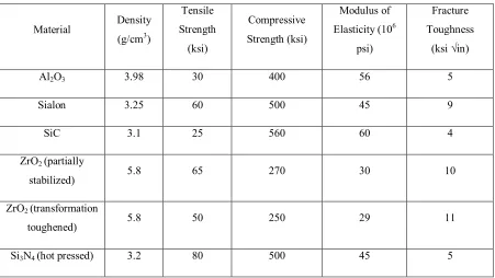
[image:23.595.81.532.407.661.2]Artistic, as a class of materials, have reliably had potential as cutting gadgets. They are hard, hold their hardness at high temperatures and have a by and large low reactivity with steel. Hence, it can be used at high cutting velocities without contorting or crumbling wears frames deciding device life. The disservice to stoneware as device materials is that absence of toughness and protection from both mechanical and warm stun. This has compelled the use of imaginative device materials before. There are three arrangements available, to be particular unadulterated oxide fired, blended oxide in addition to carbide and nitride and silicon nitride based material. Each class has its own trademark properties, which must be understood if the materials are to be most effectively manhandled in metal cutting.
Table 2.1 Mechanical properties of ceramic materials (Black and Kohser, 2008)
Material Density
(g/cm3)
Tensile Strength (ksi) Compressive Strength (ksi) Modulus of Elasticity (106
psi)
Fracture Toughness
(ksi √in)
Al2O3 3.98 30 400 56 5
Sialon 3.25 60 500 45 9
SiC 3.1 25 560 60 4
ZrO2 (partially
stabilized) 5.8 65 270 30 10
ZrO2 (transformation
toughened) 5.8 50 250 29 11
9 2.1.4 Alumina-based Ceramic Cutting Tool
The excellent properties of alumina-based pottery, for example, high resistance from scraped spot, high hot hardness, and its compound inactivity against unforgiving environment settle on it a dependable decision as a material for cutting tool. Because of its unrivaled properties, alumina is normally utilized as cutting apparatus in the application at hoisted temperature contrasted with rapid steels and carbides (Rejab et al, 2014)]. The study on alumina to contemplate its potential as a cutting apparatus has been directed since 1905 by the Germans. The hot pressing method is utilized to set up the alumina cutting supplements utilizing couple of sorts of sintering specialists, such as, Cr2O3, MgO,NiO and TiO2. These sintering specialists are generally named white porcelain (Like et al, 2007). Alumina cutting inserts, which contain fewer than 2% porosity, are comprised of fine grains, which under 5 µm, has moderately high density. The cutting embeds are appropriate to be utilized as a part of the machining of alloy steel, cast iron with hardness beneath than HB235 and carbide steel with hardness underneath than HRC38. (Azhar et al, 2010).