© 2019, IRJET | Impact Factor value: 7.211 | ISO 9001:2008 Certified Journal | Page 3885
A Modern Lightning System for Power Saving Application
Kiran Varade
1, Rohit Pawar
2, Pratik Sonawane
31Assistant Professor, Electrical Dept, S.V.I.T, Chincholi, Nashik, Maharashtra ,India
2, 3 B.E Student, Electrical Dept, S.V.I.T, Chincholi Nashik, Maharashtra ,India
---***---Abstract -
Electrical energy is the most popularenergy due to the following advantages like-smooth operation, ease of handling, easy to conversion, better efficiency , easy to start etc. The main purpose of Electrical power system is to generate and supply the energy to consumers.t The demand of electrical energy is increased day by day due to the increasing population so increased the generation of electrical energy is important so we have choose the thermoelectric generator for generation of electricity from waste heat of the motor, transformer etc. This waste heat recovered by TEG and electricity generated is used to street lamp.
Key Words: Thermoelectric Generator (TEG),Voltage Regulator, Thermoelectric Module.
1.INTRODUCTION
Thermoelectric generator it is device which is use for the directly conversion of heat energy into the form of electrical energy. It is works on the seebeck principle
Waste heat in manufacturing is generated from several industrial systems distributed throughout a plant. The largest sources of waste heat for most industries are exhaust and flue gases and heated air from heating systems such as high-temperature gases from burners in process heating; lower temperature gases from heat treating furnaces, dryers, and heaters; and heat from heat exchangers, cooling liquids, and gases. While waste heat in the form of exhaust gases is readily recognized, waste heat can also be found within
liquids and solids. Waste heat within liquids includes cooling water, heated wash water, and blow-down water. Solids can be hot products that are discharged after processing or after reactions are complete, or they can be hot by-products from processes or combustion of solid materials. Other less apparent waste heat sources include hot surfaces, steam leaks, and boiler blow-down water. Exhibit 1 shows typical major waste heat sources along with the temperature range and characteristics of the source.
1.1 THERMOELECTRIC GENERATOR COMPONENTS
Thermoelectric power generator basically consist of four major components :
Hot side heat exchanger
Themoelectric module
Cold –side heat exchanger
Copper electrodes
1.2 CONVENTIONAL MATERIALS
There are many TEG materials that are employed in commercial applications today. These materials can be divided into three groups based on the temperature range of operation:
© 2019, IRJET | Impact Factor value: 7.211 | ISO 9001:2008 Certified Journal | Page 3886 combinations
with Antimony (Sb), Tellurium (Te) or Selenium (Se).
2. Intermediate temperature (up to 850K): such as materials based on alloys of Lead (Pb) 3. Highest temperatures material (up to 1300K):
materials fabricated from silicon germanium (SiGe) alloys.
[image:2.595.321.559.113.302.2]Although these materials still remain the cornerstone for commercial and practical applications in thermoelectric power generation, significant advances have been made in synthesizing new materials and fabricating material structures with improved .
Fig .Constructional diagram of TEG
2. System Design
2.1 Working Principle Of TEG
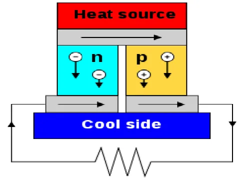
A thermoelectric generator (TEG), also called a Seebeck generator, is a solid state device that converts heat flux (temperature differences) directly into electrical energy through a phenomenon called the Seebeck Thermoelectric generators function like heat engines, but are less bulky and have no moving parts. However, TEGs are typically more expensive and less efficient. As shown in fig (1)
Fig 2 Principle diagram of TEG
Thermoelectric generators could be used in power plants in order to convert waste heat into additional electrical power and in automobiles as automotive thermoelectric generators (ATGs) to increase fuel efficiency. Another application is radioisotope thermoelectric generators which are used in space probes, which has the same mechanism but use radioisotopes to generate the required heat difference.
© 2019, IRJET | Impact Factor value: 7.211 | ISO 9001:2008 Certified Journal | Page 3887 For many years, the main three semiconductors known
to have both low thermal conductivity and high power factor were bismuth telluride (Bi2Te3), lead
telluride (PbTe), and silicon germanium (SiGe). These materials have very rare elements which make them very expensive compounds.
Today, the thermal conductivity of semiconductors can be lowered without affecting their high electrical properties using nanotechnology. This can be achieved by creating nanoscale features such as particles, wires or interfaces in bulk semiconductor materials. However, the manufacturing processes of nano-materials is still challenging.
A thermoelectric module is a circuit containing thermoelectric materials that generate electricity from heat directly. A thermoelectric module consists of two dissimilar thermoelectric materials joining in their ends: an n-type (negatively charged); and a p-type (positively charged) semiconductors. A direct electric current will flow in the circuit when there is a temperature difference between the two materials. Generally, the current magnitude has a proportional relationship with the temperature difference. (i.e., the more the temperature difference, the higher the current.)
In application, thermoelectric modules in power generation work in very tough mechanical and thermal conditions. Because they operate in very high temperature gradient, the modules are subject to large thermally induced stresses and strains for long periods of time. They also are subject to mechanical fatigue caused by large number of thermal cycles.
Thus, the junctions and materials must be selected so that they survive these tough mechanical and thermal conditions. Also, the module must be designed such that the two thermoelectric materials are thermally in parallel, but electrically in series. The efficiency of thermoelectric modules are greatly affected by its geometrical design.
2.2 FLOW CHART
3. ADVANTAGES
1. Powered by Alphabet Energy’s solid-state Power Blocks thermoelectric technology, the E1 requires virtually no maintenance, and has no need for an operator.
2. Fuel savings that add up quickly, using 32 rugged, extensively tested Power Modules that
Heat collecting plate Industrial heat
TEG plate
Street lamp Battery charging circuit
© 2019, IRJET | Impact Factor value: 7.211 | ISO 9001:2008 Certified Journal | Page 3888 can be upgraded to deliver even more power
output and fuel savings in the future.
3. Bike exhaust heat recovery is being investigated in recent years as a way to increase the efficiency of Internal Combustion engines and simultaneously to reduce CO2
emissions by converting the thermal energy to electrical, employing either thermal fluid systems (mainly the Ranking Cycle) or Thermoelectric Generators
4. The relevant increase of system efficiency is dependent on an improvement of the efficiency of commercial Thermoelectric Generators. 5. No cryogen needed. TEC modules can work
constantly for hours. It contains no pollution or rotating components, which results no noise and vibration, long life span.
4. CONCLUSIONS
In this way we have conclude that the thermoelectric generator,
It’s supplied to low power .(miliwatts)
It is beneficial to present energy crisis.
Introduce to Nanotechnology.
Development in future will lead to interasting application.
REFERENCES
1. Vazquez, J., Sanz-Bobi, M., Palacios, R. Arenas, A. 2002. “State of the Art Thermoelectric Generators Based on Heat Recovered from the
Exhaust Gases of Automobiles.” Proc., 7th European Workshop on Thermoelectrics. Pamplona, Spain, Paper # 17.
2. Zorbas, K. T., Hatzikraniotis, E. Paraskevopoulos, K. M. 2007. “Power and Efficiency Calculation in Commercial TEG and Application in Wasted Heat Recovery in Automobile.” Proc., 5th European Conference on Thermoelectrics. Odessa, Ukraine, Paper #30. 43
3. Chen, M. Andreasen, S., Rosendahl, L., Kaer, S. K., Condra, T. 2010. “System Modeling and validation of a Thermoelectric Fluidic Power Source: Proton Exchange Membrane Fuel Cell and Thermoelectric Generator.” Journal of Electronic materials, 39 (9). pp 1593-1600. 1 4. Crane, D. and LaGrandeur, J. 2010 “Progress
Report on BSST-Led US Department of Energy Automotive Waste Heat Recovery Program.” Journal of Electronic Materials. 39 (9). pp 2142-2148.
5. Serksnis, A.W. Thermoelectric Generator of Automotive Charging System. 1976. Prox. 11th Intersociety Conversion Engineering Conference. New York, USA, pp. 1614-1618.
BIOGRAPHIES
Kiran Varade1
1Assistant Professor, Electrical Dept, S.V.I.T, Chincholi, Nashik,
© 2019, IRJET | Impact Factor value: 7.211 | ISO 9001:2008 Certified Journal | Page 3889
Rohit Pawar2
B.E Student, Electrical Dept, S.V.I.T,
Chincholi Nashik, Maharashtra ,India
Pratik Sonawane3
B.E Student, Electrical Dept, S.V.I.T,