Encoderless Flux Vector Oriented Control of
Brushless Doubly-Fed Reluctance Generators
Milutin Jovanovi´c
Faculty of Engineering and Environment Northumbria University
Newcastle upon Tyne NE1 8ST, UK
Sul Ademi and Ayman Attya
Institute for Energy and EnvironmentUniversity of Strathclyde Glasgow G1 1RD, UK
Liancheng Zhu
School of Electrical Engineering Shenyang University of TechnologyShenyang 110870, China
Abstract—An angular position and velocity observer-based sensorless flux vector-oriented control scheme for a prominent doubly-fed reluctance generator has been presented and ex-perimentally validated. This technology allows the use of the same partially rated power converter as the traditional slip-ring doubly-excited induction generator, while offeslip-ring compet-itive performance with added cost benefits of high reliability and maintenance-free operation afforded by its brushless con-struction. The controller viability has been demonstrated on a laboratory machine prototype for emulated variable speed and loading conditions similar to those encountered in wind turbines.
NOMENCLATURE
BDFRG Brushless Doubly-Fed Reluctance Generator BDF(I)G Brushless Doubly-Fed (Induction) Generator DFIG Wound Rotor Doubly-Fed Induction Generator
LVRT Low-Voltage-Ride-Through
MPPT Maximum Power Point Tracking
WECS Wind Energy Conversion Systems
DT(P)C Direct Torque (Power) Control FOC Flux (Field) Oriented Control
VOC Primary Voltage Vector Oriented Control
vp,s Primary, secondary winding phase voltages [V]
ip,s Primary, secondary winding currents [A]
Rp,s Primary, secondary winding resistances [Ω]
Lp,s Primary, secondary 3-phase inductances [H]
λp,s Primary, secondary winding flux linkages [Wb]
λm, Lm Mutual flux [Wb] and 3-phase inductance [H]
ωp,s Primary, secondary winding frequencies [rad/s]
pp, ps Primary, secondary winding pole-pairs
pr Number of rotor poles (=pp+ps)
ωrm,nrm Rotor angular velocity [rad/s], speed [rev/min]
ωsyn Synchronous speed=ωp/pr [rad/s]
Pm Mechanical (shaft) power [W]
Pp,s Primary, secondary mechanical power [W]
Te Electro-magnetic torque [Nm]
P, Q Primary real [W] and reactive [VAr] power
σ Leakage factor= 1−L2
m/(LpLs)
I. INTRODUCTION
A conventional DFIG [1] has been a widely adopted option of many large-scale wind turbine manufacturers [2], [3] by virtue of its good overall performance, low-cost fractional
power electronics, and absence of expensive rare earth per-manent magnets with market supply chain volatilities [4]. In WECS, the operating speed ranges are relatively narrow (e.g. about 2:1 or so) allowing one to utterly exploit the DFIG slip-power recovery property through cost savings of the typically 70% derated bi-directional power converter [1]. The latter has also been reported to feature lower failure rates than its full-size counterpart used for synchronous generator based WECS [5]. However, these capital and running cost benefits may be offset by the DFIG main drawbacks, the compromised reliability and regular servicing of brush gear, as well as hardware protection complexities to satisfy the grid integration codes in making the small inverter LVRT compliant [1], [6].
The above DFIG limitations can be mostly eliminated with the BDFG technologies, while retaining all of the claimed advantages [6]–[8]. The BDFG can not only offer further cost cuts by the high reliability and maintenance-free operation of brushless construction [3], but the superior LVRT char-acteristics without a crowbar too due to the proportionally larger impedances, and hence reduced fault currents, than the equivalent DFIG [6], [9], [10]. Apart from the target WECS, stand-alone wind [11] and/or ship shaft power generation applications [12] are feasible.
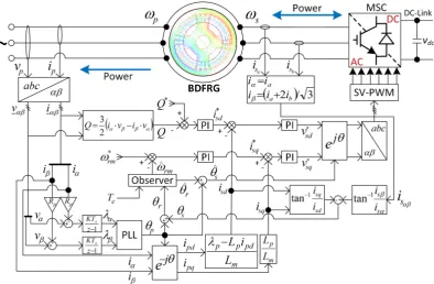
Fig. 1. A block-scheme of the sensorless speed FOC configuration for the space-vector-PWM inverter-fed BDFRG.
A VOC approach for the BDFRG was proposed and exper-imentally verified, albeit for the unloaded machine, in [17]. The follow-up theoretical preliminaries on this concept have not been practically validated [18], [19]. The same applies to the sliding mode control theory in [22]. On the other hand, DTC has been implemented in sensor [23] and sensor-less speed modes [19] but supported with unsatisfactory no-load test results as in [17]. A much improved response has been ob-tained by minimising the machine parameter dependence and sensitivity issues of this scheme in the alternative DTC, where the measurable primary reactive power is controlled instead of the estimated secondary flux [24], [25]. A complete parameter-freedom has been further achieved in its DPC concurrent [26]. However, the experiments discussed in [24]–[26] were done at fixed BDFRG loads of little interest to real WECS. Although they can be credited with ease of stator frame implementation without rotor position or velocity inputs, the hysteresis DT(P)C algorithms in [24]–[26] are all executed at variable switching rates and exhibit a generally worse harmonic content than the VOC, and especially its FOC correlative.
Significant contributions to the early VOC research [17] have been recently made with the comparative development and comprehensive practical studies of the two robust VOC and FOC techniques for the adjustable speed BDFRM (e.g. motoring) [27], [28] and the BDFRG [29], [30] under both constant [29] and variable loading conditions [27], [28], [30]. Similar realistic computer simulations of WECS using a 2 MW BDFRG design from [7] have been documented in [8].
The majority of the existing methods for the BDFRG(M) require a shaft position sensor for current and/or speed control
as well as to provide the drive train velocity information for the MPPT in WECS [1]. Sensorless operation would bring an extra degree of reliability and operation & maintenance cost reduc-tions [5]. However, these conveniences often come with some performance trade-offs by introducing the inevitable machine model reliance necessary for the position or speed estimation as demonstrated in the DTC case [19]. An exception is the latest development of a viable speed sensorless FOC scheme in [31], which has been shown to possess good disturbance rejection capabilities and smooth response using the maximum torque per inverter ampere strategy [18]. This paper is an extension to the work in [31] by presenting the principles and experimental results of reactive power control implementation on a custom-built BDFRG for speed dependent WECS-alike loading profiles.
II. BDFRG OPERATINGPRINCIPLES
The electro-mechanical energy conversion in the machine takes places under the following angular velocity and pole conditions with the mechanical power relationships reflecting the participation of each winding [16], [18]:
ωrm =
ωp+ωs
pp+ps
= (1 + ωs ωp
)·ωp pr
= (1 +ωs ωp
)·ωsyn (1)
Pm=Te·ωrm=
Te·ωp
pr
+Te·ωs pr
=Pp+Ps (2)
whereωs>0if ωrm> ωsyn, else1 ωs<0andωrm < ωsyn.
Whereas,ωs= 0(i.e. DC secondary) refers to the synchronous
1The ‘negative’ frequency at sub-synchronous speeds means the opposite
speed operation (ωrm = ωsyn) as with a classical 2pr-pole
wound field turbo-machine.
It could be easily shown using (1) that if a variable speed range of 2:1 is required in WECS, the corresponding frequency ratio should be ωp/ωs = 3, which implies the inverter real
power rating of circa Ps≈0.21Pmaccording to (2).
III. FOC MODELLINGASPECTS
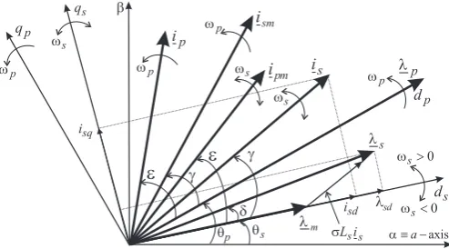
The space-vector equations for the primary andsecondary windings in rotating reference frames (Fig. 2) using standard notation andmotoring (BDFRM) convention are [16]:
vp=Rpip+ dλp
dt =Rpip+jωp·(Lpip+Lmi∗sm)
| {z }
λp
vs=Rsis+ dλs
dt =Rsis+jωs·(Lsis+Lmi∗pm)
| {z }
λs (3)
whereipmandismare the magnetically coupled (magnetizing) current vectors of the actual primary (ip) and secondary (is) current counterparts rotating at different velocities (Fig. 2). This peculiar frequency modulating action of the rotor man-ifests itself through the following important vector equalities for the sensorless controller design: ipm = ip = ipejε
and ism = is = isejγ in the corresponding d−q frames
as illustrated in Fig. 2 [16]. Given (1), such frame choice facilitates control as the secondarydq currents are then DC.
The flux FOC forms of (3), and the respective torque and 3-phase reactive power expressions, now become [27]–[31]:
λp=Lpipd+Lmismd
| {z }
λpd=λp
+j·(Lpipq−Lmismq)
| {z }
λpq=0
(4)
λs=σLsisd+λmd
| {z }
λsd
+j·(σLsisq+λmq)
| {z }
λsq
(5)
=σLsis+
Lm
Lp
λ∗p
| {z }
λm
=σLsis+
Lm
Lp
λp
| {z }
λm
(6)
Te=
Pppr
ωp
=3pr
2 λpipq= 3prLm
2Lp
λpisq=
3pr
2 λmisq (7) Q= 3
2ωpλpipd = 3 2
ωpλp
Lp
(λp−Lmisd) (8)
Note that, with the grid-locked primary winding and approx-imately constantλp, and thusλm, the FOC frame-flux vector
alignment in Fig. 2 leads to inherently decoupled control ofTe
andQthrough isq andisdby removing the problematic VOC
cross-coupling terms from (7) and (8). If left uncompensated, the latter can severely deteriorate the VOC response quality, particularly with smaller machines, as experimentally verified in [27]–[30]. The FOC approach is therefore more generic and applicable to a range of machine sizes from this point of view. Furthermore, it is amenable to sensorless control as shown in the sequel. Another important control implication of Te∼isq
and Q ∼ isd is that isq and isd can serve as the reference
[image:3.595.314.561.53.190.2]outputs of the speed and Q loops avoiding the use of (7) and (8) and handling the associated parameter uncertainties
Fig. 2. A FOC phasor diagram with the key vectors and reference frames.
through PI tuning (Fig. 1). The controller robustness of the original implementation in [31] can be elevated in this way.
IV. SENSORLESSFOC DESIGN
Theλp=λpejθp stationary frame components (Fig. 2) for
the Y-connected primary winding with an isolated neutral point and ‘ABC’ phase sequence are calculated from the line voltage and current measurements using (3) as follows:
λα=R(vα−Rpiα)dt=R(vAB+3vAC −RpiA)dt
λβ=
R
(vβ−Rpiβ)dt=
R
(v√BC
3 −Rp
iA+2√iB
3 )dt
(9)
The generated λαβ estimates are input to a conventional
PLL to filter out the transducer DC offset effects and noisy measurements in order to get the most accurateθpas the FOC
foundation. This angle is then used to find thedp−qpcurrents,
ipd andipq, and the rotor angle (θr) from the angular position
version of (1) i.e.θr=prθrm =θp+θs, as shown in Fig. 1.
The ds-axis position (θs) above is identified using (4) and
the fact that ism=is(Fig. 2):
Lpipd+Lmismd=λp=⇒isd=ismd=
λp−Lpipd
Lm
Lpipq−Lmismq = 0 =⇒isq=ismq =
Lp
Lmipq
(10) Notice that the feedback currents in Fig. 1 are directly determined by (10) regardless of θsor θr errors. In addition,
θscan now be obtained from the measured secondary currents
by applying the obvious angular relationships from Fig. 2:
θs=tan−1
isβ
isα
−tan−1isq
isd
(11)
=tan−1ia√+ 2ib 3ia
−tan−1 Lpipq
λp−Lpipd
(12)
Therefore, apart from Rp (through λp) with smaller
ma-chines, the use of (12) only needs the Lp knowledge. Yet,
as θs can still be affected by measurement noise, the raw
θr=θp+θsvalues are passed through a common load-model
based PI observer [31], [32] to eradicate erroneous estimates for accurate ωˆrm predictions. The filtered θˆr is fed back to
further enhance the quality of θˆs estimation, the emanating
Fig. 3. Oscillograms of the steady-state currents in two phases of the shorted secondary winding for the unloaded BDFRG at≈730 rev/min.
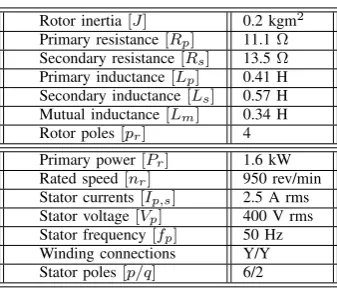
TABLE I
THEBDFRGPARAMETERS AND RATINGS
Rotor inertia[J] 0.2 kgm2
Primary resistance[Rp] 11.1Ω
Secondary resistance[Rs] 13.5Ω
Primary inductance[Lp] 0.41 H
Secondary inductance[Ls] 0.57 H
Mutual inductance[Lm] 0.34 H
Rotor poles[pr] 4
Primary power[Pr] 1.6 kW
Rated speed[nr] 950 rev/min
Stator currents[Ip,s] 2.5 A rms
Stator voltage[Vp] 400 V rms
Stator frequency[fp] 50 Hz
Winding connections Y/Y Stator poles[p/q] 6/2
V. LABORATORYTESTS
The BDFRG was started as a slip ring induction machine up to the steady no-load speed (Fig. 3), and the inverter was then enabled on the fly. The experimental results were generated by running the sensorless algorithm in Fig. 1 on a dSPACEr DS1103 platform at 2.5 kHz. The specifications of the BDFRG prototype are summarised in Table I. These data have been used to create the following shaft torque-speed profile to emulate the MPPT characteristic of WECS in the base speed region [1]:
TL=−
Pr
ωr
·
nrm
nr
2
≈ −16·nrm 950
2
Nm (13)
This expression is implemented using a commercial Parkerr DC drive operated in torque mode. The other relevant details about the BDFRG test facility can be found in [24]–[31].
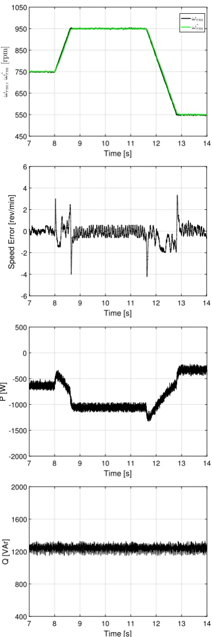
The results in Fig. 4 demonstrate an excellent tracking of the ramp speed reference trajectory in a limited range of [550-950] rev/min around the synchronous speed (750 rev/min). The effectiveness of the machine sensorless operation is clearly verified in either synchronous, super-synchronous or sub-synchronous speed modes and with marginal speed estimation
errors under both steady-state and transient conditions. The captured Q waveform properly follows the desired set-point showing overall immunity to the P variations and providing convincing evidence of the robustness afforded by the inher-ently decoupled FOC nature as expected from (7) and (8).
The observer low-pass filtering abilities are more than evident from the speed error plot in Fig. 4, which represents the deviations of the observer estimates (ωˆrm) from the actual
encoder measurements (ωrm). Although the raw θr can be
notably noisy, much the same as recorded in [31] but not in this paper for space reasons, a considerable improvement in accuracy is achieved by processingθrconsidering the virtually
overlapping trend of the corresponding ωˆrm and ωrm traces
over the entire speed range. Such an impressive sensorless controller response essentially comes from to the bulk of the quality estimates produced by the closed-loop configuration of both the position estimator itself and the high-performance observer as its central part.
The measured secondary current waveforms in Fig. 5 il-lustrate the phase sequence reversal while the BDFRG is riding through the synchronous speed from 950 rev/min to 550 rev/min. At super-synchronous speeds, theds−qsframe,
and the accompanying secondary vectors includingis, rotate in a positive (anti-clockwise) direction indicated byωs>0in
(1). In sub-synchronous speed mode, however, the secondary phase sequence is opposite to the primary withisnow rotating
clock-wise when ωs < 0 in (1). Notice that is becomes
stationary at synchronous speed (750 rev/min) as the secondary currents are then DC i.e.ωs= 0 in (1).
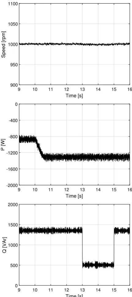
Finally, Fig. 6 is presented to reinforce the absence of cross-coupling not only in the Qresponse to ramp variations inP, but also the other way around in case of a sudden step change in Q reference, for the machine operating at 1000 rev/min. Both theP andQresponses are visibly smooth and show no apparent signs of distortion pointing out again the excellent disturbance rejection properties of the controller.
VI. CONCLUSIONS
A field-oriented speed and reactive power control algorithm for sensorless operation of the BDFRG has been validated by tests on a small machine prototype under wind turbine-alike loading conditions emulated in a laboratory environment. The scheme under consideration has been previously proposed by the author(s) in their latest work where the reactive power control has not been demonstrated. This gap has been filled by the experimental results presented in this paper.
7 8 9 10 11 12 13 14 Time [s]
450 550 650 750 850 950 1050
ω
r
m
,
ˆ
ω
r
m
[r
p
m
]
ωrm ˆ ωrm
7 8 9 10 11 12 13 14
Time [s] -6
-4 -2 0 2 4 6
Speed Error [rev/min]
7 8 9 10 11 12 13 14
Time [s] -2000
-1500 -1000 -500 0 500
P [W]
7 8 9 10 11 12 13 14
Time [s] 400
800 1200 1600 2000
[image:5.595.69.285.47.697.2]Q [VAr]
[image:5.595.312.562.51.208.2]Fig. 4. Experimental verification of the BDFRG sensorless speed control.
Fig. 5. The secondary currents showing a phase sequence reversal from super to sub-synchronous speed mode as captured on the dSPACErdesktop.
current control feedback coupled with the relatively light reliance on the machine parameters of the entire estimation procedure.
REFERENCES
[1] R. Cardenas, R. Pena, S. Alepuz, and G. Asher, “Overview of control systems for the operation of DFIGs in wind energy applications,”IEEE
Transactions on Industrial Electronics, vol. 60, no. 7, pp. 2776–2798,
2013.
[2] M. Liserre, R. Cardenas, M. Molinas, and J. Rodriguez, “Overview of multi-MW wind turbines and wind parks,” IEEE Transactions on
Industrial Electronics, vol. 58, no. 4, pp. 1081–1095, Apr. 2011.
[3] H. Polinder, J. Ferreira, B. Jensen, A. Abrahamsen, K. Atallah, and R. McMahon, “Trends in wind turbine generator systems,”IEEE Journal
of Emerging and Selected Topics in Power Electronics, vol. 1, no. 3, pp.
174–185, Sept 2013.
[4] J. G. Njiri and D. Soffker, “State-of-the-art in wind turbine control: Trends and challenges,” Renewable and Sustainable Energy Reviews, vol. 60, pp. 377–393, 2016.
[5] J. Carroll, A. McDonald, and D. McMillan, “Reliability comparison of wind turbines with DFIG and PMG drive trains,”IEEE Transactions on
Energy Conversion, vol. 30, no. 2, pp. 663–670, June 2015.
[6] S. Tohidi, P. Tavner, R. McMahon, H. Oraee, M. Zolghadri, S. Shao, and E. Abdi, “Low voltage ride-through of DFIG and brushless DFIG: Similarities and differences,”Electric Power Systems Research, vol. 110, pp. 64–72, May 2014.
[7] D. G. Dorrell and M. Jovanovi´c, “On the possibilities of using a brushless doubly-fed reluctance generator in a 2 MW wind turbine,”
IEEE Industry Applications Society Annual Meeting, pp. 1–8, Oct. 2008.
[8] S. Ademi and M. Jovanovic, “Control of emerging brushless doubly-fed reluctance wind turbine generators,” in Large Scale Renewable
Power Generation, ser. Green Energy and Technology, J. Hossain and
A. Mahmud, Eds. Springer Singapore, 2014, pp. 395–411.
[9] S. Tohidi, H. Oraee, M.-R. Zolghadri, S. Shao, and P. Tavner, “Analysis and enhancement of low-voltage ride-through capability of brushless doubly fed induction generator,”IEEE Transactions on Industrial
Elec-tronics, vol. 60, no. 3, pp. 1146–1155, March 2013.
[10] T. Long, S. Shao, P. Malliband, E. Abdi, and R. McMahon, “Crowbarless fault ride-through of the brushless doubly fed induction generator in a wind turbine under symmetrical voltage dips,”IEEE Transactions on
Industrial Electronics, vol. 60, no. 7, pp. 2833–2841, 2013.
[11] F. Zhang, L. Zhu, S. Jin, W. Cao, D. Wang, and J. L. Kirtley, “Developing a new SVPWM control strategy for open-winding brushless doubly fed reluctance generators,”IEEE Transactions on Industry Applications, vol. 51, no. 6, pp. 4567–4574, Nov/Dec 2015.
9 10 11 12 13 14 15 16
Time [s]
900 950 1000 1050 1100
Speed [rpm]
9 10 11 12 13 14 15 16
Time [s] -2000
-1600 -1200 -800 -400 0
P [W]
9 10 11 12 13 14 15 16 Time [s]
0 500 1000 1500 2000
[image:6.595.65.281.48.531.2]Q [VAr]
Fig. 6. Super-synchronous sensorless operation demonstrating excellent disturbance rejection abilities and smooth response of the decoupled FOC toP and/orQvariations at 1000 rpm.
[13] A. Knight, R. Betz, and D. Dorrell, “Design and analysis of brushless doubly fed reluctance machines,”IEEE Transactions on Industry
Appli-cations, vol. 49, no. 1, pp. 50–58, Jan/Feb 2013.
[14] A. Oraee, E. Abdi, S. Abdi, R. McMahon, and P. Tavner, “Effects of rotor winding structure on the BDFM equivalent circuit parameters,”
IEEE Transactions on Energy Conversion, vol. 30, no. 4, pp. 1660–
1669, Dec 2015.
[15] F. Wang, F. Zhang, and L. Xu, “Parameter and performance comparison of doubly-fed brushless machine with cage and reluctance rotors,”IEEE
Transactions on Industry Applications, vol. 38, no. 5, pp. 1237–1243,
2002.
[16] R. E. Betz and M. G. Jovanovi´c, “Introduction to the space vector modelling of the brushless doubly-fed reluctance machine,” Electric
Power Components and Systems, vol. 31, no. 8, pp. 729–755, 2003.
[17] L. Xu, L. Zhen, and E. Kim, “Field-orientation control of a doubly excited brushless reluctance machine,” IEEE Transactions on Industry
Applications, vol. 34, no. 1, pp. 148–155, Jan/Feb 1998.
[18] M. G. Jovanovic, R. E. Betz, and J. Yu, “The use of doubly fed reluc-tance machines for large pumps and wind turbines,”IEEE Transactions
on Industry Applications, vol. 38, pp. 1508–1516, 2002.
[19] M. Jovanovi´c, “Sensored and sensorless speed control methods for brushless doubly fed reluctance motors,” IET Electric Power
Applica-tions, vol. 3, no. 6, pp. 503–513, 2009.
[20] F. Barati, R. McMahon, S. Shao, E. Abdi, and H. Oraee, “Generalized vector control for brushless doubly fed machines with nested-loop rotor,”
IEEE Transactions on Industrial Electronics, vol. 60, no. 6, pp. 2477–
2485, June 2013.
[21] R. Zhao, A. Zhang, Y. Ma, X. Wang, J. Yan, and Z. Ma, “The dynamic control of reactive power for the brushless doubly fed induction machine with indirect stator-quantities control scheme,” IEEE Transactions on
Power Electronics, vol. 30, no. 9, pp. 5046–5057, Sept 2015.
[22] F. Valenciaga, “Second order sliding power control for a variable speed-constant frequency energy conversion system,”Energy Conversion and
Management, vol. 52, no. 12, pp. 3000–3008, 2010.
[23] M. G. Jovanovi´c, J. Yu, and E. Levi, “Encoderless direct torque controller for limited speed range applications of brushless doubly fed reluctance motors,”IEEE Transactions on Industry Applications, vol. 42, no. 3, pp. 712–722, 2006.
[24] H. Chaal and M. Jovanovi´c, “Practical implementation of sensorless torque and reactive power control of doubly fed machines,” IEEE
Transactions on Industrial Electronics, vol. 59, no. 6, pp. 2645–2653,
2012.
[25] H. Chaal and M. Jovanovic, “Toward a generic torque and reactive power controller for doubly fed machines,”IEEE Transactions on Power
Electronics, vol. 27, no. 1, pp. 113–121, 2012.
[26] ——, “Power control of brushless doubly-fed reluctance drive and generator systems,” Renewable Energy, vol. 37, no. 1, pp. 419–425, Jan 2012.
[27] S. Ademi and M. Jovanovi´c, “High-efficiency control of brushless doubly-fed machines for wind turbines and pump drives,” Energy
Conversion and Management, vol. 81, pp. 120–132, May 2014.
[28] S. Ademi, M. Jovanovi´c, and M. Hasan, “Control of brushless doubly-fed reluctance generators for wind energy conversion systems,” IEEE
Transactions on Energy Conversion, vol. 30, no. 2, pp. 596–604, June
2015.
[29] S. Ademi and M. Jovanovi´c, “Vector control methods for brushless doubly fed reluctance machines,” IEEE Transactions on Industrial
Electronics, vol. 62, no. 1, pp. 96–104, Jan 2015.
[30] S. Ademi and M. Jovanovic, “Control of doubly-fed reluctance gen-erators for wind power applications,” Renewable Energy, vol. 85, pp. 171–180, January 2016.
[31] S. Ademi, M. G. Jovanovi´c, H. Chaal, and W. Cao, “A new sensorless speed control scheme for doubly fed reluctance generators,” IEEE
Transactions on Energy Conversion, vol. PP, no. 99, pp. 1–9, 2016.
[32] R. Lorenz and K. Patten, “High-resolution velocity estimation for all-digital, ac servo drives,” IEEE Transactions on Industry Applications, vol. 27, no. 4, pp. 701–705, July/August 1991.