Volume-5 Issue-2
International Journal of Intellectual Advancements
and Research in Engineering Computations
Speed and torque control of resonant inverter fed brushless dc motor
drive using fuzzy logic controller
1
Ms.A.Saranya,
2Mrs.R.Dheivanai,
3Dr.B.Karthik
1
PG Scholar,
2Assistant professor
3Assistant professor
Department of Electrical and Electronics Engineering,
Vivekanandha Institute of Engineering and Technology for Women, Tiruchengode
Sona college of Technology, Salem
e-mail:
[email protected],
2 [email protected], 3 [email protected]Abstract— This paper presents a comparative analysis of speed control of brushless DC motor (BLDC) drive fed with conventional two-level, three and five level diode clamped resonant inverter (DC-MLI). The performance of the drive system is successfully evaluated using Fuzzy Logic (FL) based speed controller. The control structure of the proposed drive system is described. The speed and torque characteristic of conventional two-level inverter is compared with the three and five-level resonant inverter (MLI) for various operating conditions. The three and five level diode clamped resonant inverters are simulated using IGBT’s and the mathematical model of BLDC motor has been developed in MATLAB/SIMULINK environment. The simulation results show that the Fuzzy based speed controller eliminate torque ripples and provides fast speed response. The developed Fuzzy Logic model has the ability to learn instantaneously and adapt its own controller parameters based on disturbances with minimum steady state error, overshoot and rise time of the output voltage.
Keywords— high frequency (HF) resonant (HF-R) inverter, phase shift (PS) angle control, Fuzzy Logic controller, Pulse Width Modulation
I. INTRODUCTION
Brushless Direct Current (BLDC) motors are one of the motor types rapidly gaining popularity. BLDC motors
are used in industries such as Appliances, Automotive, Aerospace, Consumer, Medical, Industrial Automation Equipment and Instrumentation. As the name implies, BLDC motors do not use brushes for commutation; instead, they are electronically commutated. BLDC motors have many advantages over brushed DC motors and induction motors. A few of these are:
• Better speed versus torque characteristics • High dynamic response
• High efficiency • Long operating life • Noiseless operation • Higher speed ranges • High reliability
In order to attain the reduction of switching loss, low electromagnetic Interference (EMI) noise, and high power density effectively, the introduction of soft-switching technologies is useful in the HF resonant (HF-R) inverter. The soft-switching HF-R inverter which has been developed so far has attractive features such as the low cost and simple control schemes based on pulse frequency modulation (PFM) and pulse width modulation (PWM). However, the HF-R inverters controlled by PFM have the inherent technical issue, i.e., switching frequency limitation for the low–medium output power settings; thereby, the wide-range power regulation of the BLDC load cannot be ensured.
The Resonant inverter suitable for the coupled working coils is proposed, but performances on the soft
switching Operations are not clearly demonstrated. Therefore, the improvement of the power density is a significantly technical challenge for those previous types of inverters while constraining the switching frequency.
II. FUZZY CONTROLLER
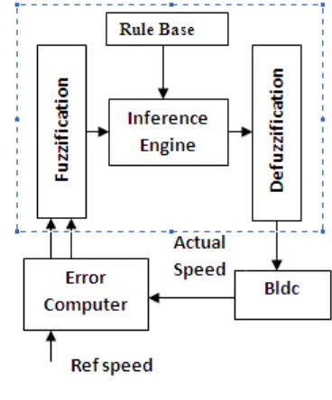
Error (E) and change in error (CE) are the inputs for the fuzzy controller whereas the output of the controller is change in duty cycle (ΔDC). The error is defined as the difference between the reference speed and actual speed, the change in error is defined as the difference between the present error and previous error and the output, Change in duty cycle ΔDC is which could be either positive or negative is added with the existing duty-cycle to determine the new duty-cycle Fig.1shows the basic structure of fuzzy logic controller. The fuzzy controller is composed of the following four elements: fuzzification, fuzzy rule-base, fuzzy inference engine and defuzzification. Fuzzy logic uses linguistic variables instead of numerical variables. The process of converting a numerical variable in to a linguistic variable is called fuzzification. The fuzzifier includes two parts: choice of membership function and choice of scaling factor. The fuzzy variables error, change in error and change in duty-cycle are quantized using the linguistic terms NB, NM, NS, Z, PS, PM, and PB (negative big, negative medium, negative small, zero, positive small, positive medium and positive big respectively).
.
Figure. 1 Fuzzy Logic Controller
A rule base (a set of If-Then rules), which contains a fuzzy logic quantification of the expert’s linguistic description of how to achieve control action. Once the
rules have been established, a fuzzy logic system can be viewed as a mapping from inputs to outputs.
Rules may be provided by experts or can be extracted from numerical data. The performance of the controller can be improved by adjusting the membership function and rules. Different types of inferential procedures to help us understand things or to make decisions, there are many different fuzzy logic inferential procedures. The fuzzy inference operation is implemented by using the 49 rules.Likewise 49 rules are defined. The same set of rules could be presented in a sliding mode format, a more compact representation given in Table 1. Finally the fuzzy output is converted into real value output by the process called defuzzification. Centroid method of defuzzification is used because it can be easily implemented and requires less computation time. The defuzzified output is obtained by the following equation
n
x n
x
x x x Z
1 1
) (
) (
Where z is the defuzzified value, μ(x) is the membership value of member x.
Table.1 Rule Base
III. RELATEDWORK
the most power full technique that offer a simple method for controlling of analog system with processors digital output. PWM frequency depends on the target FPGA device speed and duty cycle resolution requirement. In this paper, BLDC motor drive controlled using FPGA controller.
Speed control of brushless DC motor using genetic algorithm based fuzzy controller. The brushless DC motor (BLDCM) is receiving wide attention for industrial applications because of their high torque density, high efficiency and small size. Conventional controllers suffer from uncertain parameters and the non-linear of the BLDCM. The fuzzy control has been focus in the field of the control of the BLDCM. However, a systematic method for designing and tuning the fuzzy logic controller is not developed yet. In this paper, an auto-tuning method for fuzzy logic controller based on the genetic algorithm (GA) is presented. And the scheme is applied into the BLDCM control.
Two closed loops are constructed in this paper. The inner loop is current feed back which is to adjust the torque of the motor. The outer loop is the fuzzy logic controller whose control rules are optimized off-line and parameters are adjusted based on the genetic algorithm. In this paper, a program is written in Visual C++ to adjust the fuzzy controller off-line. At last, a TMS320LF2407A digital signal processor (DSP) is used to fully prove the flexibility of the control scheme in real time. Excellent flexibility and adaptability as well as high precision and good robustness are obtained by the proposed strategy.
Proportional Integral and Derivative Control of Brushless DC Motor. Brushless DC (BLDC) motors are one of the electrical drives that are rapidly gaining popularity, due to their high efficiency, good dynamic response and low maintenance. In this paper, the modeling and simulation of the BLDC motor was done using the software package MATLAB/SIMULINK.A speed controller has been designed successfully for closed loop operation of the BLDC motor so that the motor runs very closed to the reference speed. The simulated system has a fast response with small overshoot and zero steady state error.
Bishwajit Saha, Rae-Young Kim, High Power Density Series Resonant Inverter Using An Auxiliary Switched Capacitor Cell for Induction Heating Applications. The main objective of this paper is to demonstrate how high power density can be achieved by including as switched capacitor cell with the capacitor-clamped half-bridge zero voltage switching high-frequency inverter circuit using the PWM control scheme.Yungtaek Jang, Milan M. Jovanovic Pulse-Based Dead-Time Compensator for PWM Voltage Inverters the ZVS of primary switches is
achieved by employing two magnetic components whose volt-second products change in the opposite directions with A change of phase shift between the two bridge legs. Junfeng Liu, K.W.E.Cheng, JunZeng A Unified Phase-Shift Modulation for Optimized Synchronization of Parallel Resonant Inverters in High Frequency Power System. A new modulation called as unified Phase shift modulation (PSM) is proposed to integrate the regulations of magnitude and phase.
IV. PROPOSED METHOD
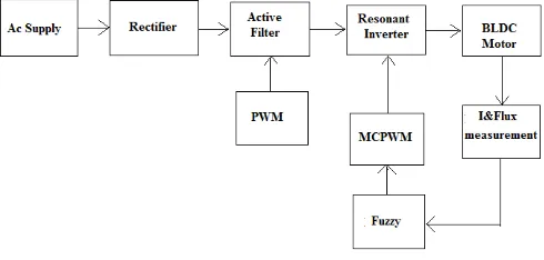
The basic proposed resonant DC link Inverter block diagram consist of a three phase input supply, diode bridge rectifier, a resonant circuit, a conventional three phase inverter for BLDC motor and control circuit including PWM generator, auxiliary switches control circuit and main switches control circuit as shown in figure.2. The three phase supply is given to the three phase diode bridge rectifier which converts AC to DC which is given to the DC link resonant circuit. The resonant circuit creates a resonant DC supply (that is, which creates a zero voltage transition ZVT) which is given to the inverter.
Figure. 2 Block Diagram
The output of the inverter is given to the BLDC motor according to switching of the control circuit based on the signal of the rotor position sensor inbuilt with motor. Prior to the availability of fully controllable power switches, thyristors was the major power devices used in power electronic circuits. Each thyristors requires a commutation circuit, which usually consists of a LC resonant circuit, for forcing the current to zero in the turn-off process. This mechanism is, in fact, a type of zero-current turn-off process. With the recent advancements in semiconductor technology, the voltage and current handling capability and the switching speed of fully controllable switches have significantly been improved.
replaces conventional power switch is introduced in this section. A resonant switch is a sub-circuit comprising a semiconductor switch S and resonant elements Lr and
Cr. The switch S can be implemented by a unidirectional
or bidirectional switch, which determines the operation mode of the resonant switch. The phase current is commutated when the DC link voltage becomes zero. There is only one DC link voltage notch per PWM cycle. It is very important especially for very low or very high duty of PWM. Otherwise the intervals between two voltage notches are very short even overlapping which will limit the tuning range. Thus the gate signal of the main switches is controlled by the synchronous pulse that will limit the tuning range.
IV. SIMULATIONRESULTS
SIMULATION DIAGRAM
Figure.3 shows the simulation circuit for Resonant Inverter operation of sensorless three phase BLDC motor. The voltage is given as an input. The inverter is used to convert dc to ac.AC supply is given to the stator windings of the BLDC motor. Fuzzy logic is used to control the speed. The battery is connected to the input of BLDC motor. Energy is conserved during the regenerative period. The inverter configuration consist of six MOSFET are connected. The MOSFET block implements a semiconductor device controllable by the gate signal. The inverter subsystem six MOSFET are connected.
Figure.3 Pulse Width Modulation
The MOSFET block implements a semiconductor device controllable by the gate signal. The MOSFET is simulated as a series combination of a resistor Ron, inductor Lon, and a DC voltage source Vf in series with a switch controlled by a logical signal (g > 0 or g = 0).The MOSFET turns on when the drain-source voltage is positive and greater than Vf and a positive signal is applied at the gate input (g > 0). It turns off when the collector-emitter voltage is positive and a 0 signal is applied at the gate input (g = 0).The MOSFET device is in the off state when the drain-source voltage is negative. Note that many commercial MOSFETs do not
have the reverse blocking capability. The MOSFET block contains a series Rs-Cs snobbier circuit, which is connected in parallel with the MOSFET device (between terminals C and E).The turnoff characteristic of the MOSFET model is approximated by two segments.
Figure.4 Rotor Speed
In Figure.4 shows the rotor speed. The speed of the BLDC motor is directly proportional to the applied voltage. The commutational logic specifies the coils that need to be energized for every 60 degree of electrical revolution based on hall signal.
Figure.5 Electromagnetic Torque
In figure.5 shows the electromagnetic torque. There are two torque parameters used to define a BLDC motor,
peak torque and rated torque. During continuous operations, the motor can be loaded up to the rated torque. In a BLDC motor, the torque remains constant
for a speed range up to the rated speed.
Figure.6 Back Emf
In figure.6 shows the back EMF. When the motor operates in the value of the back emf generated by the motor be greater than the supplied voltage.
ADVANTAGES
Speed and torque is constant
Harmonics of this inverter topology is low power factor is high
Total system efficiency is high
APPLICATIONS
These motors have been the thermal speed range of 100 to 1 at full rated torque is available on the standard motor and totally enclosed motors are available in very small frame sizes
Motor efficiencies range from 90 to 96 % and controller efficiency is 97%.
These motor are primarily used in servo, actuation, positioning, and variable speed applications where precise motion control and stable operation are critical for the satisfactory operation of the manufacturing or industrial process.
The tape and disk drives for computers, robotics and positioning systems, and in aircraft where brush wear was intolerable due to low humidity.
V. CONCLUSION
In this paper, a comparative study of Fuzzy Logic based speed control of BLDC motor drive fed with conventional two-level, three and five-level diode clamped resonant inverter is done. From the simulation results we can conclude that as the voltage level increases the performance characteristics of the BLDC drive has been improved and the harmonics in the output voltages and currents has been reduced. Also the speed and torque characteristics of BLDC drive are
having good transient and steady state response. The advantages of the Fuzzy Logic controller are that it reduces computational time, learns faster and produces lower errors than other method.
FUTURE SCOPE
The future work of this is to control the speed of BLDC motor using intelligent fuzzy logic controller. Thus the control using FLC will be more effective than this PI controller. The Future work is to implement this simulation in hardware. They have the advantage to be robust and relatively simple to design as they do not require the knowledge of the exact model. It has simple features like fixed and uniform input and output scaling factors, flat, single partition rule-base with fixed and non-interactive rules, fixed membership functions, limited number of rules, which increase exponentially with number with the number of inputs, fixed knowledge, low-Level control and no hierarchical rule structure.
REFERENCES
1. H.Sarnago, O.Lucía, A.Mediano, andJ.M.Burdío, ―Modulation scheme For improved operation of an RB-IGBT-based resonant inverter applied to
Domestic induction heating,
‖IEEETrans.Ind.Electron., . 60, no. 5, pp. 2066– 2073, May 2013.
2. Nikola Milivojevic and Mahesh Krishnamurthy, "Stability Analysis of FPGA-Based Control of Brushless DC Motors and Generators Using Digital PWM Technique‖ IEEE
Trans.Ind.Electron.,vol.59,no.1,pp.343-351,January.2012
3. C. S. Joice, Dr. S. R. Paranjothi, and Dr. V. J. S. Kumar, ―Practical implementation of four quadrant operation of three phase Brushless DC motor using dsPIC,‖ in Proc. IConRAEeCE2011, 2011, pp. 91–94, IEEE.
4. V. Esteve, E. Sanchis-Kilders, J. Jordan, E. J. Dede, C. Cases, E. Maset, J. B. Ejea, and A. Ferreres, ―Improving the efficiency of IGBT series resonant inverters using pulse density modulation,‖ IEEE Trans. Ind.Electron., vol. 58, no. 3, pp. 979–987, March 2011.
6. B. Singh and S. Singh, ―State of the art on permanent magnet brushless DC motor drives,‖ J.
Power Electron., vol. 9, no. 1, pp. 1–17, January.
2009.
7. C. Xia, Z. Li, and T. Shi, ―A control strategy for
four-switch three phase brushless DC motor using single current sensor,‖ IEEE Trans.Ind. Electron., vol. 56, no. 6, pp. 2058–2066, June 2009.
8. A. Sathyan, N. Milivojevic, Y.-J. Lee, M. Krishnamurthy, and A. Emadi, ―An FPGA-based novel digital PWM control scheme for BLDC motor drives,‖ IEEE Trans. Ind. Electron., vol. 56, no. 8, pp. 3040–3049, August. 2009.
9. A. Sathyan,M. Krishnamurthy, N.Milivojevic, and A. Emadi, ―A low cost digital control scheme
for brushless DC motor drives in domestic applications,‖ in Proc. Int. Electric Machines
Drives Conf., 2009, pp. 76–82.
10. Y.-S. Kung, ―Design and implementation of a high performance PMLSM drives using DSP chip,‖ IEEE Trans. Ind. Electron., vol. 55, no. 3,pp. 1341–1351, March. 2008