Iterative Equalization and Source Decoding for
Vector Quantized Sources
Lie-Liang Yang, Jin Wang, Rob Maunder and Lajos Hanzo
School of ECS, University of Southampton, SO17 1BJ, UKTel: +44-23-8059 3364; Fax: +44-23-8059 4508 E-mail: [email protected]; http://www-mobile.ecs.soton.ac.uk
Abstract— In this contribution an iterative (turbo) channel equalization and source decoding scheme is considered. In our in-vestigations the source is modelled as a Gaussian-Markov source, which is compressed with the aid of vector quantization. The communications channel is modelled as a time-invariant channel contaminated by intersymbol interference (ISI). Since the ISI channel can be viewed as a rate-1 encoder and since the re-dundancy of the source cannot be perfectly removed by source encoding, a joint channel equalization and source decoding scheme may be employed for enhancing the achievable performance. In our study the channel equalization and the source decoding are operated iteratively on a bit-by-bit basis under the maximum a-posteriori(MAP) criterion. The channel equalizer accepts thea pri-oriinformation provided by the source decoding and also extracts extrinsicinformation, which in turn acts asa prioriinformation for improving the source decoding performance. Simulation results are presented for characterizing the achievable performance of the iterative channel equalization and source decoding scheme. Our results show that iterative channel equalization and source decoding is capable of achieving an improved performance by efficiently exploiting the residual redundancy of the vector quanti-zation assisted source coding.
I. INTRODUCTION
In practice many communications systems may encounter the intersymbol interference (ISI), when communicating over channels having dispersion resulting from delay-spread. Con-ventionally, the ISI can be effectively mitigated with the aid of various channel equalization techniques [1], which are usu-ally implemented without invoking any knowledge about the other components, such as error-control coding and source coding. However, when error-control coding is employed, a joint (turbo) equalization and channel decoding scheme may significantly outperform the scheme that implements equaliza-tion and channel decoding separately [2], [3].
In this contribution we investigate a joint channel equal-ization and source decoding scheme, where equalequal-ization and source decoding are carried out iteratively, so as to attain an improved BER performance in comparison to the scheme em-ploying channel equalization and source decoding separately. Specifically, when the receiver obtains a set of observation sam-ples, the channel equalizer is first operated based on the MAP criterion, so as to extract extrinsic information and convey a prioriinformation to the source decoder through an interleaver.
With the aid of the a priori information extracted from the channel equalizer, source decoding is also carried out based on the MAP principle and, correspondingly,extrinsicinformation is generated. Thisextrinsic information is further fed back to the channel equalizer, so as to provide it with a priori infor-mation for enhancing the next round of channel equalization. The above-described iterative channel equalization and source decoding process can be continued until no further iteration gain is available or until the maximum number of iterations is reached.
In our study the source is assumed to be a Gaussian-Markov source [4], which is encoded with the aid of vector quantization. The channel is modelled as a time-invariant ISI channel. Our study and simulation results show that the iterative equalization and source decoding scheme is capable of efficiently exploiting the residual redundancy of vector quantization for improving the BER performance. Specifically, for both the 3-path and the 5-path ISI channels considered, an approximately 2dB iteration gain may be achievable, when employing iterative channel equalization and source decoding, instead of carrying out channel equalization and source decoding separately.
II. PRELIMINARIES
A. Vector Quantization
Assume that the source {Xn} is a zero-mean, stationary and Gaussian-Markov vector process. The source encoder is a vector quantizer [4], which is described as follows. The source encoder, E: Rk → IN, whereIN = {0,1, . . . , N −1} and where it is assumed thatN= 2L, maps thek-dimensional real-valued source vectorXn ∈ Rk to a finite representationIn ∈
IN, where In = E(Xn). The encoder mappingE is defined
by a partition {Ri}Ni=0−1 of thek-dimensional hyperspace Rk such that we have Xn ∈ Ri ⇒ In = i. Hence, the set Ri
is referred to as the ith encoder region or cell. Let us define the encoder centroids, {c(i)}Ni=0−1 as ci E[Xn|In=i] =
E[Xn|Xn∈ Ri]. The ordered set {c(i)}Ni=0−1 is usually re-ferred to as the codebook of sizeN, whilei∈ IN is the index
of theith codeword. Letbl(i)∈ {−1,+1}, l= 0,1, . . . , L−1 be the bits in the binary representation of the (arbitrary) integer
i∈ IN. As shown in Fig. 1, let{Xn=xn}Nn=0s−1beNsnumber
of source vectors and {In=in}Nn=0s−1 be their corresponding
Vector Binary mapping channelISI Interleaver
Π
×
wmym {dm}
NsL
m=1
{bm}Nms=1L
{In}Nn=0s−1
{Xn}Nn=0s−1
quantizer
Fig. 1. Representation of a data transmission system including source coding and an interleaver signaling over an intersymbol interference (ISI) channel contaminated by additive Gaussian noise.
indices at the encoder output. Then, as shown in Fig. 1, these indeces are mapped to a binary sequence {bm}Nms=1L, where
b(nL+l+ 1) = bl(in). Then, the binary sequence is input to an interleaver, where the binary data is interleaved according to the interleaving functionΠ. The output of the interleaver is expressed as{dm}Nms=1L. Finally, the interleaved data{dm}Nms=1L
is transmitted over an ISI channel with additive white Gaussian noise (AWGN), as shown in Fig. 1.
B. Channel Model
We assume a coherent symbol-spaced receiver front-end and perfect knowledge of the signal phase and symbol timing, such that the channel can be approximated by an equivalent, discrete-time baseband model. Consequently, the transmitter filter, the channel and the receiver filter can be jointly represented by a discrete-time linear filter with its finite-length impulse response expressed as
hm=
M
k=0
hlδ(l−k) (1)
where the (real-valued) channel coefficients{hk}are assumed
to be time-invariant and known to the receiver. Given the channel impulse response (CIR) of (1) and binary phase shift keying (BPSK) data modulation, the channel outputym, which
is also the equalizer’s input, is given by
ym=
M
k=0
hkdm−k+wm, m= 1, . . . , Nc (2)
where wmis the zero-mean AWGN having a variance of σ2, Nc =NsL+NhandNhrepresents the tail-bits concatenated
by the transmitter, in order to take into account the ISI delay. Specifically,Nh =M number of 0s can be transmitted at the tail of a message, so that the discrete-time linear filter converges to the state of zero. Explicitly, the channel output sample ofym
obeys a conditional Gaussian distribution having the probability
[image:2.595.62.294.39.164.2] [image:2.595.314.561.39.137.2]0 1 0 1 0 0 1 1 0 0 1 1 0 1 0 1 0 0 1 1 0 0 1 1 0 1 0 1 0 0 1 1 0 0 1 1 0 1 0 1 0 0 1 1 0 0 1 1 00 11 00 11 00 00 11 11 00 00 11 11 00 11 00 11 00 00 11 11 00 00 11 11 0 1 0 1 0 0 1 1 0 0 1 1 0 1 0 1 0 0 1 1 0 0 1 1 00 11 00 11 00 00 11 11 00 00 11 11 00 11 00 11 00 00 11 11 00 00 11 11 0 1 0 1 0 0 1 1 0 0 1 1 0 1 0 1 0 0 1 1 0 0 1 1 00 11 00 11 00 00 11 11 00 00 11 11 00 11 00 11 00 00 11 11 00 00 11 11 0 1 0 1 0 0 1 1 0 0 1 1 0 1 0 1 0 0 1 1 0 0 1 1 00 11 00 11 00 00 11 11 00 00 11 11 00 11 00 11 00 00 11 11 00 00 11 11 00 11 00 11 00 00 11 11 00 00 11 11 00 11 00 11 00 00 11 11 00 00 11 11 ... ... ... 000 001 010 011 100 101 110 111 000 001 010 011 100 101 110 111 -1
0 1 2 3 4 Nc−4 Nc−3Nc−2 Nc−1 d1= 1
Nc
Fig. 2. Trellis diagram of an ISI channel model associated withM= 3.
density function (PDF) expressed as
pym(y|dm, dm−1, . . . , dm−M)
= √1 2πσexp
y− M k=0
hkdm−k
2
2σ2
(3)
Let us denote the state of the equivalent discrete-time channel at time nTb, where Tb represents the bit duration by qn =
(dn, dn−1, . . . , dn−M+1). Then, the channel output sampleyn
at nTb depends on the channel state qn−1 and on the input binary symboldn. Hence, the equivalent discrete-time channel
can be modelled as a Markov chain and its behavior can be represented by a trellis diagram. As an example, Fig.2 shows the trellis diagram of an ISI channel model associated with
M = 3. In this figure and also in our forthcoming discourse we assume that the channel state starts and terminates at state zero.
III. ITERATIVECHANNELEQUALIZATION ANDSOURCE DECODING
In this section we consider the principles of iterative channel equalization and source decoding, and consider the extrinsic
information that is exchanged between the equalizer and the source decoder. We assume that the source is Gaussian-Markov and that the indeces output by the source encoder can be modelled by a Vth-order Gaussian-Markov process [5]. At the receiver, both the equalizer and the source decoder output soft information, which is derived based on themaximum a-posteriori(MAP) criterion. Finally, soft source decoding [6], [7] is employed for the reconstruction of the transmitted source vectors, in the sense that the source decoder carries out a map-ping of the continuous-valued information to a source vector estimate.
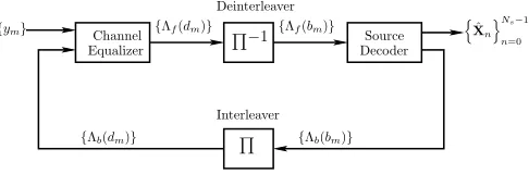
The receiver structure performing iterative equalization and source decoding is shown in Fig.3. The ultimate objective of the receiver is to provide estimates to the source{Xn}, given the channel output samplesyyNc
1 . More specifically, in the
back thea prioriinformation associated with each data bit to the channel equalizer through an interleaver having the interleaving function expressed by Π. The information conveyed on the feedback path is identified byΛb( ). This process is repeated for a number of times, until finally the source decoder outputs the estimates Xˆn
for the source vectors{Xn}, with the aid of the information provided by{Λf(bm)}. Let us first investigate the channel equalization process a little further.
A. MAP-Assisted Equalization
Decoder
Π
DeinterleaverInterleaver Equalizer
Channel
Π
−1 Source{ym}
{Λb(bm)} {Λf(bm)}
{Λb(dm)}
{Λf(dm)} XˆnNs−1
[image:3.595.54.297.188.268.2]n=0
Fig. 3. Receiver schematic performing iterative channel equalization and source decoding.
The channel equalizer considered in this contribution is based on the MAP algorithm, which has been widely employed in turbo decoding [8]–[10]. The MAP equalizer outputs the channel information, which is expressed as {Λf(dm)}, asso-ciated with all data bits, givenNc received samples expressed
by y = yNc
1 as well as the a priori information {Λb(dm)}
corresponding to all data bits. The feed-forward information Λf(dm)corresponding to bitdmis given by
Λf(dm) lnP(dm= +1|y)
P(dm=−1|y)−ln
P(dm= +1)
P(dm=−1) = Λ(dm|y)−Λb(dm) (4)
whereΛ(dm|y) = ln [P(dm= +1|y)/P(dm=−1|y)] repre-sents thea posteriorilog likelihood ratio (LLR) of the datadm,
which can be expressed as by following the approaches in [8], [9], [11], [12],
Λ (dm|y) = ln
qm
qm−1
αm−1(i)γ+1(ym,i,j)βm(j)
qm
qm−1
αm−1(i)γ−1(ym,i,j)βm(j) (5)
where we have
αm(i) =
qm−1
u
αm−1(i)γu(ym,i,i) (6)
βm(j) =
qm+1
u
γu(ym+1,j,j)βm+1(j) (7)
γu(ym,i,j) = P(dm=u;qm=j;ym|qm−1=i) (8)
which can be determined using the BJCR algorithm [11] or the SOVA algorithm [8].
B. MAP-Assisted Source Decoding
The information output by the equalizer is conveyed to the source decoder through a deinterleaver associated with the deinterleaving function ofΠ−1. The correspondinga pri-ori information input to the source decoder is expressed as Λf(bm) for the mth bit, where m = 1,2, . . . , Nc. For the sake of convenience, we use ΛΛΛf to express the collection of Λf(bm) values for m = 1,2, . . . , Nc, and use Λf(bm2
m1)
to express the collection of Λf(bm) for m = m1, m1 + 1, . . . , m2. The MAP source decoder computes the a
pos-teriori probabilities (APPs) P(bm = u|ΛΛΛf) = P(bm =
u|Λf(b1),Λf(b2), . . . ,Λf(bNc)), u= +1,−1from theNcbit
LLRsΛΛΛf, and outputs the difference
Λb(bm) = lnP(bm= +1|ΛΛΛf)
P(bm=−1|ΛΛΛf)−ln
P(bm= +1)
P(bm=−1) (9) = Λ (bm|ΛΛΛf)−Λf(bm), m= 1, . . . , Nc (10)
where Λf(bm) represents the a-priori LLR of the data bit
bm, which is provided by the equalizer seen in Fig.3. In (10)
Λ (bm|ΛΛΛf) = ln [P(bm= +1|ΛΛΛf)/P(bm=−1|ΛΛΛf)] repre-sents the a-posteriori LLR of bm, which is the information
about the data bit bm gleaned from the a priori information
about the other data bits based on the characteristics of the source code. Below a recursive algorithm is derived for com-putingΛ (bm|ΛΛΛf), m= 1,2, . . . , Nc, which is essentially the modified version of the BCJR algorithm [11].
For the sake of generality, we assume aVth order Markov source, which can be modelled by a stationary stochastic pro-cess{In}Nn˜=1s , whereN˜s ≥Ns+Nh/Landxrepresents
the lowest integer no less thanx. Let
st= (It, It−1, . . . , It−V+1) (11)
be the state of the Markov process at the reference time instant oft, which corresponds to thetth receivedL-bit source symbol. It can be shown that the state ofstis fully determined by the statest−1as well as the input source symbolItat timet. Hence, the Markov source and its behavior can be represented by a trellis diagram. This trellis diagram has a total of2V L states, and there are2Lbranches emanating from and entering each of the states. A path segment in the trellis fromt=atot=b > a is determined by the states that are located on this path within
a≤t≤b, which can be expressed as
Lb
a (sa,sa+1, . . . ,sb) (12) Denote the input source symbol that engenders the state transition from st−1 = s to st = s byIt = it(s, s). Let
us assume that theLnumber of bits init(s, s)are expressed
byblit(s, s) L−1
l=0, and that they are independent, since there
Consequently, the transition probability from st−1 = s to st=s, givenΛΛΛf, can be expressed as
P(st=s|st−1=s; ΛΛΛf) =P[It=it(s, s)|ΛΛΛf] =
L−1
l=0
Pblit(s
, s)|ΛΛΛ
f (13)
wherePblit(s, s)|ΛΛΛf
can be expressed as [13]
Pblit(s, s)|ΛΛΛf
= 1 2
1 +blit(s, s) tanh
1
2Λf(bL(t−1)+l)
(14)
LetSSS+l be the set of state pairs(s, s)such that thelth bit, wherel = 0,1, . . . , L−1, of the source symbolIt =it(s, s) is+1, i.e., such thatblit(s, s) = +1. Similarly, we defineSSS−l
as the set of state pairs(s, s)such thatbilt(s, s) =−1. Then,
the LLR ofΛ (bm|ΛΛΛf)corresponding tom= (t−1)L+lin (10) can be expressed as
Λ (bm|ΛΛΛf) = lnP(bm= +1|ΛΛΛf)
P(bm=−1|ΛΛΛf)
= ln
(s,s)∈SSS+
l
α(ts−)1(s)β(ts)(s)P(ssst=s|ssst−1=s; ΛΛΛf)
(s,s)∈SSS−
l
α(t−s)1(s)βt(s)(s)P(ssst=s|ssst−1=s; ΛΛΛf) (15)
where, by definition, we have
α(ts)(s) = Lt
0:ssst=s
PLt0|ΛΛΛf (16)
β(ts)(s) =
LNs˜ t :ssst=s
P
LN˜s t |ΛΛΛf
(17)
Explicitly, according to the BCJR algorithm [11], the quantities
α(ts)(s)in (16) andβt(s)(s)in (17) can be computed using the
following forward and backward recursion equations:
α(ts)(s) =
ssst−1=s
α(ts−)1(s)P(ssst=s|ssst−1=s; ΛΛΛf),
t= 1,2, . . . ,N˜s (18) β(ts)(s) =
ssst+1=s
βt(+1s)(s)P(ssst+1=s|ssst=s; ΛΛΛf), t= ˜Ns−1,N˜s−2, . . . ,0 (19)
The boundary conditions for (18) are α0(s)(000) = 1 and
α(0s)(s) = 0 for s = 000, and for (19) are βN(˜s)
s(000) = 1 and βN(˜s)
s(s) = 0 for s = 000. Finally, in (15), (18) and (19) the
probability expressed in the form ofP(ssst=s|ssst−1=s; ΛΛΛf) can be computed by using (13).
C. Source Symbol Reconstruction
After a few iterations between the channel equalizer de-scribed by (4) and the source decoder shown in (10), the source decoder of Fig.3 finally attempts to reconstruct the transmitted message using soft source decoding. The soft source decoding
is a minimum mean square error (MMSE) estimator [6]. Its objective is to compute the estimate,xˆnof the source symbol, xnbased on the LLRs ofΛ (bm|ΛΛΛf) m= 1,2, . . . , NsL. The
MMSE estimator can be expressed as
ˆ
Xn(ΛΛΛf) =
N−1
i=0
E[Xn|In=i]P(In =i|ΛΛΛf)
=
N−1
i=0
c(i)P(In=i|ΛΛΛf) (20)
ˆ
Xn(ΛΛΛf(n)) ≈
N−1
i=0
c(i)P(In=i|ΛΛΛf(n)),
n= 0,1, . . . , Ns−1 (21)
where the approximation of (20) by (21) becomes possible by considering only the LLRs related to thenth source symbol, where c(i) = E[Xn|In=i], i = 0,1, . . . , N − 1, are the codewords or centroids of each vector quantization par-tition. Let the binary representation of In = i be expressed as[b0(i), b1(i), . . . , bL−1(i)]and their corresponding LLRs as ΛΛΛf(n) = [Λf(0),Λf(1), . . . ,Λf(L−1)]. Furthermore, we assume that b0(i), b1(i), . . . , bL−1(i) are independent. Then,
the second term in (21) can be written as
P(In=i|ΛΛΛf(n)) =
L−1
l=0
P[bl(i)|Λf(l)]
=
L−1
l=0
1 2
1 +bl(i) tanh
1 2Λf(l)
(22)
IV. PERFORMANCEEXAMPLES
In this section we use two examples in order to show the advantages of using iterative channel equalization and source decoding of vector quantization sources. In our simulations characterized in both Figs.4 and 5 a first-order Markov source was assumed, and the source space was partitioned into 16 regions. Hence, the corresponding codebook employs 16 code vectors, which were indexed by 16 number of 4-bit indices. In the context of Fig.4 the 3-path ISI channel was assumed and its channel impulse response (CIR) was assumed to satisfy the constraint of CIR=[0.407,0.815,0.407], where the quantity represents the root mean square power of a corresponding path. By contrast, in Fig.5 a 5-path ISI channel was assumed and its CIR was CIR=[0.227,0.46,0.688,0.46,0.277].
CIR=[0.407, 0.815, 0.407]
0 1 2 3 4 5 6 7 8 9 10 11 12 13 14 Ebb/N0(dB)
10-5 10-4 10-3 10-2 10-1 100
Bit
Error
Rate
[image:5.595.73.287.58.233.2]Iteration 3 Iteration 2 Iteration 1 No iteration
Fig. 4. BER versus SNR per bit performance for iterative equalization and source decoding, when the 3-path channel has the channel impulse response (CIR) obeying CIR=[0.407,0.815,0.407] and when a first-order Markov source having the correlation coefficientρ= 0.9is assumed.
capable of achieving a higher iteration gain. More specifically, at the BER of10−3, the iterative gain for the 3-path channel is about 1.5dB, while that for the 5-path channel is about 1.8dB. The highest achievable iterative gain for the 3-path channel of Fig.4 is about 1.8dB, while that for the 5-path channel of Fig.5 is about 2.3dB.
V. CONCLUSIONS
In this contribution we have investigated iterative (turbo) channel equalization and source decoding, when vector quan-tized source message is transmitted over time-invariant ISI channels. From our analysis and simulation results we may conclude that the iterative channel equalization and source decoding scheme is capable of efficiently exploiting the redun-dancy that is not removable by the vector quantization assisted source encoding scheme and hence the overall BER perfor-mance can be improved. In comparison to the scheme carrying out channel equalization and source decoding separately, the iterative scheme is capable of achieving a SNR gain of about 2dB, when the source is modelled as a first-order Gaussian-Markov source and when the ISI channel has three or five paths, respectively.
ACKNOWLEDGMENT
The financial support of the EPSRC, UK and that of the EU under the auspices of the Phoenix and Newcom projects is gratefully acknowledged.
REFERENCES
[1] J. G. Proakis,Digital Communications. McGraw Hill, 3rd ed., 1995.
CIR=[0.227,0.46,0.688,0.46,0.277]
0 1 2 3 4 5 6 7 8 9 10 11 12 13 14 Eb/N0(dB)
10-5 10-4 10-3 10-2 10-1 100
Bit
Error
Rate
Iteration 3 Iteration 2 Iteration 1 No iteration
Fig. 5. BER versus SNR per bit performance for iterative equalization and source decoding, when the 5-path channel has the channel impulse response (CIR) obeying CIR=[0.227,0.46,0.688,0.46,0.277]and when a first-order Markov source having the correlation coefficientρ= 0.9is assumed.
[2] C. Douillard, M. Jezequel, and C. Berrou, “Iterative correction of in-tersymbol interference: turbo-equalization,”European Transactions on Telecommunications, vol. 6, pp. 507 – 511, September - October 1995. [3] M. Tuchler, R. Koetter, and A. C. Singer, “Turbo equalization: Principles
and new results,”IEEE Transactions on Communications, vol. 50, pp. 754 – 767, May 2002.
[4] A. Gersho and R. M. Gray,Vector Quantization and Signal Compression. Boston/Dordrecht/London: Kluwer Academic Publishers, 1991. [5] H. J. Larson and B. O. Shubert, Probabilitic Models in Engineering
Sciences, Volume I: Random Variables and Stochastic Processes. New York: John Wiley & Sons, 1979.
[6] M. Skoglund, “Soft decoding for vector quantization over noisy channels with memory,”IEEE Transactions on Informations, vol. 45, pp. 1293– 1307, May 1999.
[7] M. O. Skoglund, “Bit-estimate based decoding for vector quantization over noisy channels with intersymbol interference,”IEEE Transactions on Communications, vol. 48, pp. 1309–1317, August 2000.
[8] C. Berrou and A. Glavieux, “Near optimum error correcting coding and decoding: turbo codes,”IEEE Transactions on Communications, vol. 44, pp. 1261–1271, October 1996.
[9] J. Hagenauer, E. Offer, and L. Papke, “Iterative decoding of binary block and convolutional codes,” IEEE Transactions on Information Theory, vol. 42, pp. 429–445, March 1996.
[10] L. Hanzo, C. H. Wong, and M. S. Yee,Adaptive Wireless Transceivers : Turbo-Coded, Turbo-Equalised and Space-Time Coded TDMA, CDMA, MC-CDMA and OFDM Systems. John Wiley & Sons - IEEE Press, 2002. [11] L. R. Bahl, J. Cocke, F. Jelinek, and J. Raviv, “Optimal decoding of linear codes for minimizing symbol error rate,”IEEE Transactions on Information Theory, vol. 20, pp. 284–287, March 1974.
[12] L. R. Rabiner, “A tutorial on hidden Markov models and selected applica-tions in speech recognition,”Proceedings of the IEEE, vol. 77, pp. 257– 286, February 1989.
[image:5.595.335.549.58.233.2]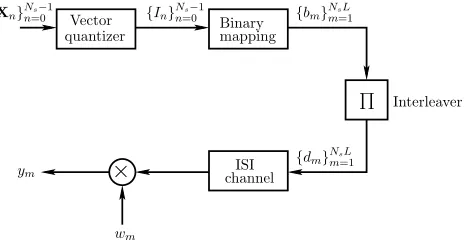
![Fig. 5.BER versus SNR per bit performance for iterative equalization andMarkov source having the correlation coefficientsource decoding, when the 5-path channel has the channel impulse response(CIR) obeying CIR=[0.227, 0.46, 0.688, 0.46, 0.277] and when a first-order ρ = 0.9 is assumed.](https://thumb-us.123doks.com/thumbv2/123dok_us/8506582.348972/5.595.73.287.58.233/performance-iterative-equalization-andmarkov-correlation-coefcientsource-decoding-response.webp)
