This is a repository copy of
Analytical optimisation of electromagnetic design of a linear
(tubular) switched reluctance motor
.
White Rose Research Online URL for this paper:
http://eprints.whiterose.ac.uk/90317/
Version: Accepted Version
Proceedings Paper:
Corda, J (2015) Analytical optimisation of electromagnetic design of a linear (tubular)
switched reluctance motor. In: Proceedings of the XVII International Symposium on
Electromagnetic Fields in Mechatronics, Electrical and Electronic Engineering (ISEF
2015). XVII International Symposium on Electromagnetic Fields in Mechatronics, Electrical
and Electronic Engineering (ISEF 2015), 10-12 Sep 2015, Valencia, Spain. . ISBN
978-84-606-9102-0
[email protected] https://eprints.whiterose.ac.uk/ Reuse
Unless indicated otherwise, fulltext items are protected by copyright with all rights reserved. The copyright exception in section 29 of the Copyright, Designs and Patents Act 1988 allows the making of a single copy solely for the purpose of non-commercial research or private study within the limits of fair dealing. The publisher or other rights-holder may allow further reproduction and re-use of this version - refer to the White Rose Research Online record for this item. Where records identify the publisher as the copyright holder, users can verify any specific terms of use on the publisher’s website.
Takedown
If you consider content in White Rose Research Online to be in breach of UK law, please notify us by
ISEF 2015 – XVII International Symposium on Electromagnetic Fields in Mechatronics, Electrical and Electronic Engineering
Valencia, Spain, September 10-12, 2015
ANALYTICAL OPTIMISATION OF ELECTROMAGETIC DESIGN
OF A LINEAR (TUBULAR) SWITCHED RELUCTANCE MOTOR
J. Corda
University of Leeds, School of Electronic and Electrical Engineering, Leeds LS2 9JT, United Kingdom e-mail: [email protected]
Abstract – The paper presents a method for optimising radial proportions of the magnetic circuit of a linear tubular switched reluctance motor in terms of maximising the developed thrust from a given machine volume at constant (rated) dissipation. The method is based on the use of analytically derived expressions for the machine’s phase inductance in the position of full misalignment between phase saliencies and mover teeth, and the flux-linkage vs. current relationship in the aligned position. The average thrust is calculated from a complete cycle of co-energy change.
Introduction
Linear switched reluctance (SR) motors, alike their rotary counterparts, are increasingly popular as variable-speed drives, due to simple brushless construction and absence of permanent magnets. A longitudinal cross-section of a linear 4-phase SR machine in tubular (cylindrical) form [1] is shown in Fig 1. The machine consists of the transversely slotted inner part, referred here as the mover, and the outer cylindrical assembly comprising a number of identical phase sets with casing and linear bearings, referred here as the stator. Each phase set consists of the ferromagnetic core formed of two discs, which are spaced by a ring-shaped back-of-core, and a solenoidal coil accommodated within the core. The phases are spaced from each other by non-magnetic rings. The machine operates in conjunction with a power electronic converter [2] which is commutated from a position detector [3], altogether forming a linear switched reluctance drive.
Performance prediction of a SR machine requires the input magnetisation data in the form of flux-linkage/current/position characteristics, as shown in Fig 2. For a hypothetical machine, these characteristics are defined by geometric parameters, number of turns and B-H curve, and can be computed by using widely available software packages for field analysis based on finite-element methods (FEM). However for a typical SR machine with small airgap and saturated magnetic
Fig.2 Set of magnetisation characteristics for range of positions
Fig.1 Longitudinal cross-sectional view through the 4-phase linear tubular SR machine
circuit the optimisation procedure based on FEM, which involves variations of several circuit parameters through a large number of incremental changes, consumes a considerable time.
This paper outlines a rapid estimation of magnetisation characteristics which is useful in analytical modelling and optimisation of a linear tubular switched reluctance machine.
Estimation of Phase Inductances
The magnetic field pattern in a linear tubular SR machine is symmetrical with respect to the machine longitudinal axis. This implies that the cross-sectional area of a flux tube, and hence the flux-density, varies along the tube which requires appropriate adaptation in deriving the partial permeances compared to the method originally developed for a rotary SR machine [4]. The method is based on an approximation based on splitting the phase flux into 3-D tubes of cylindrical and toroidal form, which are represented by straight-line and circular-arc segments in 2-D field plots as shown in Fig 3.
(a) (b)
Fig.3 Sketch of approximate phase field paths in: (a) fully misaligned position and (b) aligned positions
In fully misaligned position, the air parhs of the field lines are long and the mmf drop in the iron paths is small compared to that of the air paths. Thus when deriving analytical expressions it is justifiable to assume that the iron is infinitely permeable which implies that the field lines are perpendicular to the iron surface. In this position the inductance can be treated as independent of the excitation current. (The inductance in this position is here from referred to as the minimum inductance.)
The following set of parameters is used to define the magnetic core geometry:
Stator outside diameter (do ); Inner diameter of the back-of-core ring (di ); Stator pole disc width (v ); Spacing between adjacent phases (u); Mover outside diameter (dm ); Mover diameter in the slot (ds );
Mover pole tooth width (t ); Mover slot width (s ); Radial air-gap length between the stator and the rotor poles (g )
The axial width of the stator back-of-core ring is given by: 2w = 2(t + s) – v
The radial width of the coil is taken as:
z = (
di – dm) / 2 – gMinimum Inductance
[image:4.595.180.434.372.532.2]In fully misaligned position the flux is represented by nine tubes (components) and their field paths in the longitudinal cross-sectional plane are shown in Fig 3a. The points on the excited stator pole (shown on the figure’s right side) where field lines diverge are defined by the condition of equal magnetic field strengths along the two diverging field lines.
Figure 4 shows detail with the tube of flux-linkage 1. The radial distance of the ‘diverge’ point A from the mover pole surface is denoted with symbol k and it is determined as follows.
Fig.4 Detail with the tube of flux-linkage 1
The field lines AP and AA'A'' are linked respectively with the fractions (1–k / z) and (1– k2 /(4w z)) of the total number of turns N per phase.
The axial distance m between the stator and mover pole tips can be expressed as m = (s – v) / 2, and the lengths of field lines l1 and l9 can be expressed as (k + (k – m – t)) / 2 and w.
Using the equation for magnetic field strengths along lines AP and AA'A''
9 9
1
1 mmf mmf
l
l i.e.
) 2
( 2
) 4 1 ( )
1 (
2
t m k
I N z w k
w I N
z k
(1)
the radial distance of point A from the mover pole surface is found as being
k
[image:4.595.120.379.674.722.2]z w z t + m z t mt m t + m + z =
k 2 2 ( ) 4 12
3 1 3
2 2 2 2
(2)
The average field strength along an elementary flux path at radius x1 is proportional to the fraction of the number of turns linked with the path, and inversely proportional to the overall length of the path in the air (which is twice the length shown in the sketch of Fig 4, due to the symmetry of return path), i.e.
) 4 / 1 ( 2 1 1 1 z w x x I N H
(3)(Segment A'A'', which is small in comparison with the overall length AA'', is ignored.)
The average cross-sectional area of elementary flux tube is expressed as
1 1 1 ) 2 2 (
2 d + x dx
=
dA
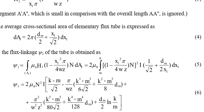
m (4)So the flux-linkage 1 of the tube is obtained as
[image:5.595.96.499.181.403.2]1 1 2 2 1 0 1 1 2 1 0 ) ( 1 ) 2 2 1 ( ] ) 4 1 [( 2 ) 4 1 ( 1 dx x d I N z w x dA N wz x H m k m A
(5) m k d + d m -k + m -k z w + d m -k + m -k wz -m -k I N m m m ln 2 ) 128 2 80 ( ) 8 2 6 ( 2 2 4 4 5 5 2 2 2 2 2 3 3 2 0 1
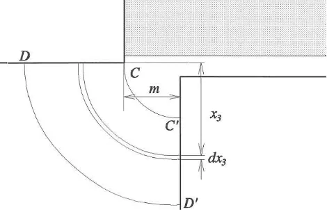
(6)Figure 5 shows detail with the tube of flux-linkage 2. Referring to Fig 3a above almost the entire number of turns is linked with any elementary field path within the tube and the average field strength, taking the symmetrical return path into account, is simply expressed as
m I N
H2 (7)
Thus the flux-linkage 2 of the tube is obtained as
2 N 0H2(dm g)m (8) [image:5.595.178.417.535.709.2]
2
0N2I (dm g) (9)Figure 6 shows detail with the tube of flux-linkage 3. Here too the entire number of turns is linked with any elementary field path within the tube.
Fig.6 Detail with the tube of flux-linkage 3
The flux-linkage 3 of the tube is obtained as
3 3 2
/
3 0
3 )
2 2
(
2 d g x dx
x I N
N m
v m
m
(10)] 2 2 / ln ) 2 [( 2 0 3
v m
v m g d I
N m
(11)Referring to Fig 3a the tubes 4 and 5 are respectively identical with tubes 3 and 4. Hence
3 4
(12)
2 5
(13)
Other components of the flux-linkage are derived in analogous manner with the above. It should be noted when deriving a combined expression for the flux-linkage components 6 , 7 and 8 , that
the ‘emanating’ and ‘returning’ field paths are symmetrical for inner phases, whereas they are
asymmetrical for the outer phases. (Each inner phase is ‘surrounded’ by adjacent phases on both sides, whereas each outer phase is ‘surrounded’ by adjacent phase on one side only.)
The minimum inductance is found as
I
L j
j
9
1 min
(14)
Maximum Inductance
In aligned position, shown in Fig 3b, the mmf drop in the ferromagnetic core cannot be ignored as well the impact of magnetic saturation on the value of inductance at different levels of the excitation current.
Due to the fringing effect at pole tips, the ‘effective’ cross-sectional area of the flux tube in the airgap is bigger than the area of the pole surface. To make some allowance for this effect, the field
line which leads from the point of ‘diverge’ on the stator pole side is approximated by a circular arc
of radius r such that the length of the semicircle is equal to the spacing between adjacent phases.
u v
r v
veff 2(1 ) 2(1 )
(15)
where r = u / and symbol denotes Carter’s coefficient given by
2 2 1 ln 4 2 tan arc 2 g r r g g r
(16)
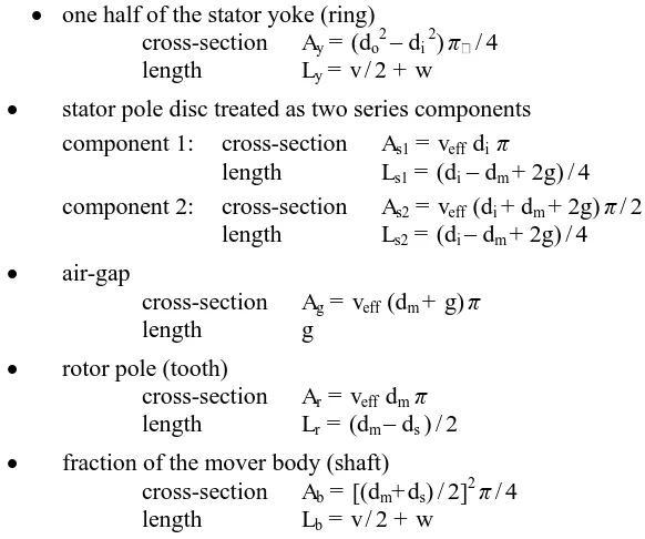
As the radial airgap length g is much smaller than the pole width, it is justifiable to assume that in aligned position the entire flux passes through effective airgap area. A further simplification is made by splitting the magnetic circuit into a series of the following elements:
one half of the stator yoke (ring)
cross-section Ay = (do2– di 2) / 4 length Ly = v / 2 + w
stator pole disc treated as two series components component 1: cross-section As1 = veff di
length Ls1 = (di – dm + 2g) / 4 component 2: cross-section As2 = veff (di + dm + 2g) / 2
length Ls2 = (di – dm + 2g) / 4
air-gap
cross-section Ag = veff (dm + g) length g
rotor pole (tooth)
cross-section Ar = veff dm length Lr = (dm – ds ) / 2
fraction of the mover body (shaft)
cross-section Ab = [(dm+ ds) / 2]2 / 4 length Lb = v / 2 + w
The relationship between the flux-linkage and current is expressed implicitly through the mmf equation
)
(
2
0L
H
L
H
L
H
L
H
L
H
g
B
=
I
N
s1 s1 s2 s2 y y b b r rg
(17) [image:7.595.93.384.216.459.2]Finding the value of flux-linkage for a given current requires an iterative approach in solving Eq (17). To avoid iterative procedure, the value of current is being found for a given flux-linkage, i.e. the value of flux density in each element of the series can be calculated for different values of flux-linkage and the corresponding value of the field strength can be obtained using the B-H characteristic of the magnetic core material. Values of inductance at different levels of flux-linkage are found by dividing the flux-linkage with the corresponding current.
Table 1 gives an indication how the calculated values of inductance in fully misaligned and aligned positions compare with values obtained by measurements and FEM computations. The results are related to the prototype machine having the number of turns per phase N = 410 and the following geometric parameters of the core constructed from mild steel:
Stator outside diameter, do = 80 mm; Inner diameter of the back-of-core ring, di = 74; Stator pole disc width, v = 4 mm; Spacing between adjacent phases, u = 3.5 mm; Mover outside diameter, dm = 40 mm; Mover diameter in the slot, ds = 28;
Table 1: Comparison of measured and estimated results
Current [A] Measured values Analytically calculated Computed by FEM Lmin [H] Lmax [H] Lmin [H] Lmax [H] Lmin [H] Lmax [H]
0.5 0.158 0.310 0.147 0.270 0.155 0.290
3 0.166 0.210 0.147 0.167 0.152 0.171
Measured values are obtained by applying the methodology described in [2] which allows the presence of magnetic saturation and eliminates the impact of eddy currents, i.e. it provides measurement of pure inductance. Other methods bases on applying d.c. voltage step or pulse, which also allow presence of magnetic saturation, do not eliminate entirely the impact of eddy-currents.
Optimisation of Radial Proportions
The electromagnetic circuit optimisation aims to determine the proportions of the magnetic circuit which provides development of maximum force from a given volume of the core defined by the outer diameter and length. The variation of radial parameters is being considered here. The axial parameters such as the mover pitch and spacing between phases are determined by the number of phases and overall length, and the ratio ‘pole width / mover pitch’ is kept constant (4/10). The inner diameter of the back-of-core ring is determined by the condition that the flux density in the ring matches the mean value of flux density in the pole disc. The radial airgap length is kept at the minimum size which is practically achievable with slide bearings made out of bronze. So the two remaining internal parameters – the mover outside diameter (dm) and slot diameter (ds), which defines the slot depth, are considered as variables.
The variations of either the mover diameter or the slot diameter affect the level of magnetic saturation. Furthermore the phase coil resistance is affected by the variation of the mover diameter and therefore the optimisation is conducted under condition of constant coils dissipation of rated level. Under such a condition, it can be assumed that the radial parameter variations within the investigated range have insignificant effect on the heat transfer, i.e. the rated temperature rise can be considered unaffected.
When the machine operates in a dual-phase mode of excitation, each phase coil is energised over a half-cycle which is equal to a linear displacement of a half of the mover pitch, i.e. the four phase coils (A, B, C, D) are excited with currents of ‘ideally’ square waveforms, which are mutually shifted in phase by a quarter of the mover pitch length. The four phase currents produce thrust components with waveforms which are overlapping each other alternatively through the pattern AB, BC, CD, DA.
The average linear force (thrust) per phase can be expressed as change of co-energy per cycle of linear displacement, i.e.
di Fph
1
(18)
where denotes the mover pitch length.
Fig.7 Illustration of co-energy area defining the average force per phase
Diagram of Fig 8 relates to the optimisation of radial proportions of the 4-phase linear switched reluctance machine of the volume defined by the outside core diameter and length as in the prototype machine (80 and 106 mm) under excitation with phase currents of 'square' waveform having magnitude of 3.2 A. The geometry with mover diameter in the range between 38 and 40 mm, and slot diameter between 32 and 34 mm is capable of developing the thrust of around 155 N.
Fig.8 Optimisation of radial proportions of the 4-phase linear SR machine with outside core diameter 80 mm and length 106 mm, under excitation of 3.2 A
References
[1] J. Corda and E. Skopljak, "Linear switched reluctance actuator", IEE Publication No.376, Oxford, Sept.1993, pp 535-539
[2] J. Corda J and S. M. Jamil, “Experimental determination of equivalent circuit parameters of a tubular
switched reluctance machine with solid steel magnetic core”, IEEE Transactions on Industrial Electronics, Vol.57, No.1, Jan.2010, pp 304-310
[3] J. Corda J and B. Ouhab, "Discrete position sensing for a linear switched reluctance motor", IEE Publication No.475, London, Sept. 2000, pp 317-320