Ames Laboratory Technical Reports
Ames Laboratory
10-1959
Vanadium-chromium alloy system
O. N. Carlson
Iowa State University
A. L. Eustice
Iowa State UniversityFollow this and additional works at:
http://lib.dr.iastate.edu/ameslab_isreports
Part of the
Metallurgy Commons
This Report is brought to you for free and open access by the Ames Laboratory at Iowa State University Digital Repository. It has been accepted for inclusion in Ames Laboratory Technical Reports by an authorized administrator of Iowa State University Digital Repository. For more information, please [email protected].
Recommended Citation
Vanadium-chromium alloy system
Abstract
On the basis of data obtaiined from melting point determinations, microscopic examination, and x-ray investigations, a phase I diagram is proposed for the V -Cr alloy system. The system forms a complete series of solid solutions with a minimum occurring in the solidus at 1750°C and approximately 70 w/o Cr. No
intermediate phases were found in this system. Hardness and corrosion data are presented as a function of alloying composition.
Disciplines Metallurgy
VANADIUM-CHROMIUM
ALLOY SYSTEM
by
0. N. Carlson and A. L. Eustice
UNCLASSIFIED
IS-47
Metallurgy and Ceramics (UC-25) TID-4500, August 1, 1959
UNITED STATES ATOMIC ENERGY COMMISSION Research and Development Report
VANADIUM-CHROMIUM ALLOY SYSTEM
by
0. N. Carlson and A. L. Eustice
Physical Sciences Reading Room
November 1959
Ames Laboratory at
Iowa State University of Science_ and Technology F. H. Spedding, Director
Contract W -7405 eng-82
2 IS-47
This report is distributed according to the category Metallurgy and Ceramics (UC-25) as listed in TID-4500, August l, 1959.
Legal Notice
This repo!tt was prepared as an account of Government sponsored work. Neither the United States, nor the Commission, nor any person acting on behalf of the Commission:
A. Makes any warranty of representation, express or implied, with respect to the accuracy, completeness, or usefulness of the information contained in this report, or that the use of any information., apparatus, method, or process disclosed in this report may not infringe privately owned rights; or B. Assumes any liabilities with respect to the use of, or for
damages resulting from the use of any information, apparatus, method, or process disclosed in this report.
As used in the above, "person acting on behalf of the Commission" includes any employee or contractor of the Commission, or employee of such contractor, to the extent that such employee or contractor of the Commission, or employee of such contractor prepares, dis-seminates, or provides access to, any information pursuant to his employment or contract with the Commission, or his employment with such contractor.
Printed in USA. Price
$
b
.
75 Available from the Office of Technical ServicesIS-47
TABLE OF CONTENTS
ABSTRACT . . . . .. . . . INTRODUCTION . . . o • • • • • • • • • • • • • • • • • • • • • • • • • • • • • • • • • • • • • • • • •
EXPERIMENTAL PROCEDURE . . . . • . . . • . . . • . . . Alloy Preparation.
Heat Treatment .. . . .
Alloy Examination . . . . X-ray Powder Patterns ..
Determination of Solidus . • . • . . . • . . . • . . .. . . EXPERIMENTAL RESULTS . . • . . . • . • . . . • . ••• o • o • • • • o • o • • •
PRO-PERTIES OF ALLOYS. o o o o . o o o . o o o o o o . o • • • • o o o o o o o o o • • • • • •
SUMMARY . . . . . . . . . . . . ... .. . . . ., . . . .
3
5
5
6 6
7
7 8 8
9
5
VANADIUM-CHROMIUM ALLOY SYSTEM
0 . N. Carlson and A. L. Eustice
Abstract--On the basis of data obtiiined from melting point determin-ations, microscopic examination, and x-ray investigations, a phase
I
diagram is proposed for the V -Cr alloy system. The system forms a
complete series of solid solutions with a minimum occurring in the
solidus at l750°C and approximately 70 w/o Cr. No intermediate phases were found in this system. Hardness and corrosion data are presented
as a function of alloying composition.
INTRODUCTION
The investigation of the vanadium-chromium alloy system was
undertaken because of interest in the corrosion resistance of the alloys and in the possible existence of intermediate phases in the system. Preliminary studies of vanadium-chromium alloys reported by other
investigators ( 1 ' 2) indicated that extensive solid solubility occurs in
this system. No intermediate phases were reported.
This investigation confirms the results of the earlier studies·
and proposes a phase diagram for the system. Data are also reported
for hardness, lattice constants, and corrosion resistance of a number of alloys.
( 1) W. Rostoker and A. Yamamoto: A Survey of Vanadium BinarySystems. Trans. ASM (1954) 46, p. 1136.
(2) H. Martens and P. Duwez: Phase Relationship in the
' 6
EXPERIMENTAL PROCEDURE
Electrolytic chromium of 99+ percent purity was obtained from
the Electro Metallurgical Company. The platelets were arc -melted
into "buttons 11 and these were used in preparing the alloys.
The authors prepared the vanadium metal by reduction of vanadium
pentoxide with calcium, as described by Long. (3 ) Vanadium pentoxide
(C. P. grade) was obtained from the Vanadium Corporation of America,
and redistilled calcium was prepared by the authors for use as the
reductant. The purity of the vanadium was estimated at approximately
99.7 percent based upon chemical and spectrographic analyses. The
chief impurities were iron(. 02 w/o), silicon L 02 w/o), oxygen
(. 02 w/ o), carbon (. 08 w/o), and nitrogen (D2 w/o). The as-reduced
vanadium was arc -melted and cut into pieces of suitable size for
preparation of the alloys.
Alloy Preparation
Weighed pieces of vanadium and chromium buttons were arc-melted
together under a helium atmosphere. Each alloy was melted at least
five times, inverting between each melt, to insure homogeneity. An
appreciable weight loss was noted in the resulting alloys( which was
attributed solely to the volatilization of chromium during the
arc-melting). The compositions of these alloys, therefore, are reported /
on the basis of their weight after arc-melting.
(3) J. R. Long and H. A. Wilhelm: Preparation of Vanadium Metal.
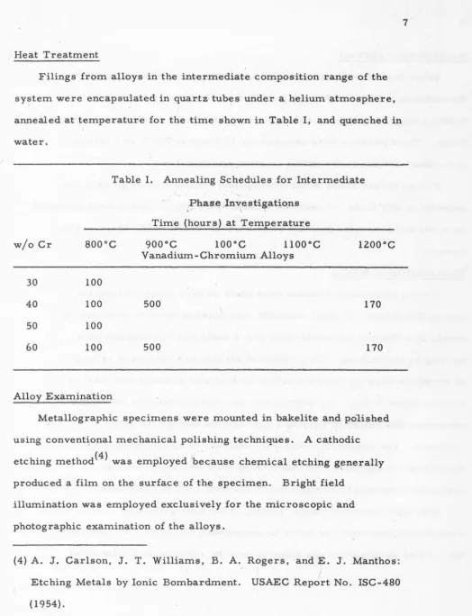
Heat Treatment
Filings from alloys in the intermediate composition range of the
system were encapsulated in quartz tubes under a helium atmosphere,
annealed at temperature for the time shown in Table I, and quenched in water.
Table I. Annealing Schedules for Intermediate
w/o Cr soooc
30 100
40 100
50 100
60
100Alloy Examination
Phase _lnvestigatio_ns Time (hours). at Temperature
Vanadium-Chromium Alloys 500 500 1200oc 170 170
Metallographic specimens were mounted in bakelite and polished using convent~onal mechanical polishing techniques. A cathodic etching method( 4 ) was employed 1because chemical etching
g~nerally
produced a film on the surface of the specimen. Brightfie1d illumination was employed exclusively for the microscopic and photographic examination of the alloys.
(4) A. J. Carlson, J. T. Williams, B. A. Rogers, and E. J. Manthos: Etching Metals by Ionic Bombardment.
(1954).
I 1.
[image:10.604.64.588.40.724.2]8
X- ray Powder Patterns
Debye-Scherrer powder patterns were taken using filtered copper
Ka radiation. Alloys containing greater than 60 w/o chromium were
brittle enough to crush, but below this composition the powders were obtained by
filing. These powders were annealed for 12 hours at 700°C in a helium
atmosphere for use in the lattice constant determinations.
Filings of four alloys in the intermediate composition range were also
annealed at 800°C for 100 hours as indicated in Table I. These were examined
by x-ray techniques for possible evidence of an intermetallic phase in this
system.
Determination of Solidus
Melting point measurements were made on bars prepared from the
arc-melted alloys. A small· sighthole was bored in the side of the bar by
means of a Glennite ultrasonic drill with a short piece of tungsten wire
serving as the drill bit. This method of drilling was necessary as most
of the alloys were too hard and brittle to drill with ordinary tool steel or
carbide-tipped drills. The melting bar was clamped between two copper
electrodes and heated by passing a high current through the alloy
specimen. The temperature was observed with an optical pyrometer
focused on the sighthole , and the melting point was determined by
noting the temperature at which liquid was first evident in the hole.
With high chromium alloys, filming of the sight glass was
encountered even when run under an atmosphere of helium. To eliminate
9
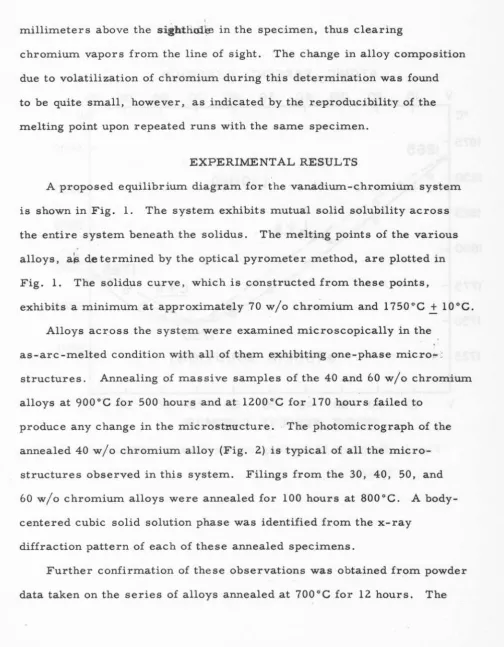
millimeters above the sig'htho.H:e in the specimen, thus clearing
chromium vapors from the line of sight. The change in alloy composition
due to volatilization of chromium during this determination was found
to be quite small, however, as indicated by the reproducibility of the
melting point upon repeated runs with the same specimen.
EXPERIMENTAL RESULTS
A proposed equilibrium diagram for the vanadium-c,hromium system
is shown in Fig. 1. The system exhibits mutual solid solubility across
the entire system beneath the solidus. The melting points of the various
alloys, ab. determined by the optical pyrometer method, are plotted in
Fig. 1. The solidus curve, which is constructed from these points,
exhibits a minimum at approximately70 w/o chromium and 1750°C
+
l0°C.Alloys across the system were examined microscopically in the
as-arc-melted condition with all of them exhibiting one-phase micro1--;
structures. Annealing of massive samples of the 40 and 60 w/o chromium
alloys at 900
oc
for 500 hours and .at 1200oc
for· 170 hours failed toproduce any change in the microstnlltcture . . The photomicrograph of the
annealed 40 w/o chromium alloy (Fig. 2) ,is typical of all the
micro-structures observed in this system. Filings from the 30, 40, 50,.· and
60 w/o chromium alloys were annealed for 100 hours .at 800°C. A
body-centered cubic solid solution phase was identified from the x-ray
diffraction pattern of each of these annealed specimens.
Further confirmation of these observations was obtained from powder
[image:12.604.63.568.85.733.2]10
oc
1875
·
1850
1825
1800
1775
1750
1725
v
ATOMIC PERCENT CHROMIUM
10
20
30
40
50
60
70
80
,
90
Cr
LIQUID
1785
L+a,...1)
~a
(SOLID
,
SOLUTION)
,
Of"
3400
3300
.
3250
3200
3150
V
·
·
10
.
20
30
40
-'
50
60
70
80
90
·.
Cr
- WEIGHT PERCENT CHROMIUM
Fig. l - Proposed Phase Diagram for Vanadium-Chromium
Fig. 2 - 40 w/o Cr Alloy Annealed at 900°C for
500 Hours. One phase, solid solution
alloy. Cathodically etched. 250X.
12
lattice constant of each alloy .was
the Nelson-Riley function, (S) 1/2
determined by an extrapolation of
cos 2 6 cos 2 6
sin
e
e
,
toe
= 90 o. Thevalues obtained by this method are plotted in Fig. 3 as a function of
atomic percent chromium. The negative deviation from Vegard's law,
which was observed, frequently occurs in systems exhibiting a minimum
in the solidus. It is therefore concluded that no compounds or regions
of solid immiscibility occur in this system.
It should be noted that the melting points reported for vanadium and
chromium are lower than the values frequently found in the technical
literature. These values were obtained on the commerical grades of
metal employed in this investigation. A melting point of 1890°C
+
l5°Cwas obtained on some vanadium prepared by the iodide process. Likewise,
a few grams of high purity chromium metal were obtained from the U.S.
Bureau of Mines at Albany, Oregon. The melting point of this metal
was determined to be 1845°C + l5°C, The amounts of the common
interstitial impurities in these materials are listed in Table II. From
these values it is probable that the solidus and liquidus curves
indicated in the proposed diagram are displaced a few degrees below
their true equilibrium positions.
(5) J. B. Nelson and D. P. Riley: An Experimental Investigation of
Extrapolation Methods in the Derivation of Accurate Unit-Cell
Dimensions in Crystals. Proc. Phys. Soc. (Londop') (194ti) 57, p. 160.
-13
3.04
3.0354
3.02
3.00
.
o<(
2.98
...
z
~
2.96
(/)
z
0
2.94
(.)
~
'
2.92
....
....
<(
2.90
...12.88
~.86
v
1
o
20
30
40
50
60
.
,
10
eo
so
cr
ATOMIC PERCENT CHROMIUM
Fig. 3 - Lattice Constant vs Atomic Percent Chromium
14
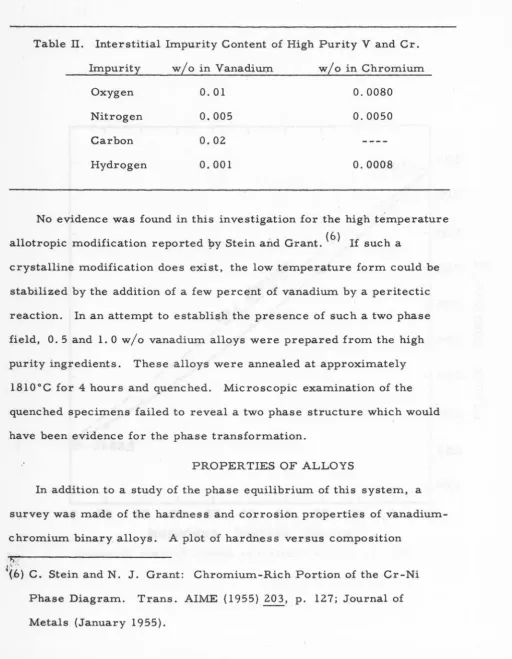
Table II. Interstitial Impurity Content of High Purity V and Cr.
Impurity w/o in Vanadiw:n w/o in Chromium
Oxygen 0. 01 0.0080
Nitrogen 0.005 0.0050
Carbon 0.02
Hydrogen 0.001 0.0008
No evidence was found in this investigation for the high temperature
allotropic modification reported yy Stein an.d Grant. ( 6 ) If such a
crystalline modification does exist, the low temperature form could be
stabilized by the addition of a few percent of vanadium by a peritectic
reaction. In an attempt to establish the presence of such a two phase
field, 0. 5 and 1. 0 w / o vanadium alloys were prepared from the high
purity ingredients. These alloys were annealed at approximately
18l0°C for 4 hours and quenched. Microscopic examination of the
quenched specimens failed to reveal a two phase structure which would
have been evidence for the phase transformation.
.
·
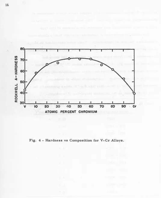
PROPER TIES OF ALLOYSIn addition to a study of the phase equilibrium of this system, . a
survey was made of the hardness and corrosion properties
ofvanadium-chromium binary alloys. A plot of hardness versus composition
4
(
.
6)
G. Stein and N.J.
Grant: Chromium-Rich Portion of the Cr-NiPhase Diagram. Trans. AIME (1955) 203, p. 127; Journal of
[image:17.602.20.533.66.726.2](see Fig. 4) gives a symmetrically ,shaped curve with a maximum at
, .approximately 50 atomic percent. This behavior, which is typical of
i
solid solution hardening, was expected for a system of this type.
The oxidation properties of tantalum"vanadium binary alloys were
studied as a function of composition. Tests were carried out on alloys
at ten percent composition intervals across the system and on the pure
components. Data from tests made at 500°C for 600 hours are
presented in Table III. At temperatures above 500
oc
the oxidationrate of vanadium and the alloys increases catastrophically d~ to the
formation of a low melting, nonprotective oxide of vanadium. A curve
obtained from a plot of these data (see Fig. 5) shows graphically the
effect of chromium on the oxidation properties of vanadium.
Table III.··· Weight Gain of V-Cr Alloys after 600 Hours in 500°C Air.
Alloy Composition Weight Gain (mg/ em 2 )
lOOV 32.5
90V- !OCr 25.5
80V :_ 20Cr 19.5
70V- 30Cr 3.0
61Y - 39Cr 4.0
50V - 50Cr 6.5
40V- 60Cr 2.0
30V - 70Cr 1.5
20V- 80Cr 2.4
lOV - 90Cr 1.5
lOOCr 0.5
[image:18.602.75.580.116.722.2]16
eo
en en
I&J
z
0
~
:J:
I
<(
...1 ...1 I&J ;t ~
(.) 0
a:
30
v
104
0
6060
70
eo
go
·
.
cr
ATOMIC PERCENT CHROMIUM
[image:19.610.9.544.56.713.2]36----~---~~---
32
-
<X (!)12
....
:I:
8
(!)
-
LLJ4
3:
v
·
10
20
30
40
50
GO
10
so
90
VIE
I
G
H
T
0/o
CHROMIUM
Fig. 5 -Oxidation Rate after 600 Hours for V-Cr Alloys , L18
SUMMARY
The investigation of the vanadium-chromium alloy system revealed
the following features:
1. The system consists of a complete series of solid solutions.
2. A minimum exists in the solidus at 70 w/o Cr and 1750°C.
3. No intermediate phases exist at the temperatures investigated.
4. The rate of oxidation of V -Cr alloys exhibits a pronounced