Analysis
of
microsprings
for
calculating
the
force produced
by
microactuators
Lijie
Li,
DeepakG
Uttamchandani* Microsystems GroupDepartment ofElectronic and Electrical Engineering University
of
Strathclyde204 George Street
Glasgow
Gi
1XW, UKAbstract:
We present models
of
two typesof
microsprings namely box-spring and zig-zag spring that can be usedto
measurethe
force generated by microactuators. The spring constant for both springsis
calculatedby
FEM using ANSYSsoftware.
In
these models,the
effectsof
short beams that act as connectorsin
the
spring structures are consideredand analyzed
by
changing their width. Also, from the results, we find thatthe
box spring appears more balancedthan the zig-zag spring when
the
forceis
appliedin the
single central direction.A
seriesof
SDAs with box spring have been fabricated and forces ofthose SDAs have been calculated.Keywords:
microspring, microactuator, box spring, zig-zag springIntroduction:
Microactuators offer many applications
in
MEMS (Microelectromechanical System) technology. MEMS devicesthat require
to be
moved must have microactuatorsto
drive themin
orderto
achieve some special functions [1].Different devices have different actuation requirement and
the
forces that they needto
operateare
also different. The calculationof
a
microactuator's force is therefore very important. Certain microactuators use microspringsto
pullthem back
to
the original position bythe
restoration force ofthe spring, because these actuators are single directionactuators.
An
exampleof
thisis the
scratch drive actuator [2]. Microsprings can be usedto
measurethe
force ofmicroactuators
by
measuringthe
displacement ofthe spring, providingthe
spring constantis
known. Therefore,it
isimportant
to
developthe
model for sucha
spring. In termsof
modelingof
these springsthe
spring constant can be controlled by adjustingthe
dimensions and geometryof
the springs.In
this paper, two typesof
springs have beentwo types
of
springsare
analyzed assumingthe
spring has been fabricatedby
a
polysilicon surface micromachiningprocess. All
the
material propertiesofthe
polysilicon usedin
this analysis applyto
the
MUMPs process [3].The in-plane behavior
ofthe
zig-zag spring and box spring are analyzed bythe
finite-element method usingthe
PC ANSYS software.A
numberof
springs having different dimensions have been analyzed using this method.Scratch drive actuators (SDAs) with two box-springs have been fabricated by
the
MUMPs process. The SDA platedimensions
are
65um width and 75um length,the
spring widthis
2um. The force characterof
these SDAs ismeasured.
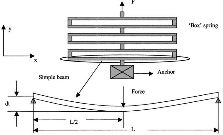
1. 'Box' spring in-plane distortion
We first begin
to
analysethe
box spring using simple formulae from mechanical beam theoryto
obtain anapproximate value. The geometry
ofthe
springis
schematically illustratedin
Fig. 2. This spring contains three boxes connected togetherby
two short bars. Allthe
bars have been designedas the
same width. We call each boxa
cell.F
h....-
... ... .. 'Box' springAnchor
Force
Fig. 1. The geometry
ofthe
'box' spring.'L' is
the lengthof
single beam,'dt' is
the maximum displacement ofbeam.'F'
is
the force appliedto
the middle ofthe beam.All
the
three cellsare
ofthe same structure and we only needto
analyse one ofthese cells. Fromthe
Figure, one cellcontains four mechanical beams, two short beams and two long beams. The force
is
appliedin
they
direction andwe assume that
the
two short beams cannot stretchin
they
direction. Selecting oneof
two long beams, centre loaded ySimple beam
[image:2.612.111.483.357.582.2]clamped beam theory can be used
to
calculate the displacementin
this case. The centre displacementof
theclamped-clamped beam under centre loading is[4]:
FL3
dt=
(1)1
92E1
Where,
'dt'
is the
displacementat
centre positionin the
y-axis,'F'
is the
force appliedto
the
centre ofthe beam, 'L'is
the length ofthe beam,'E'
is
the Young's Modulus, and'I'
is the
momentof
inertia.So
the
spring constantofN
'boxes' connected togetheris
easily obtained as (assumingthe
shortbars
ofbox have noeffect
on the
spring constant) as follows:96E1
k=
(2)nL
We assume
the
following: E=169GPa, L=50 j.irn,n'3,
polysilicon thicknessis
2
.tm, width ofpolysiliconis 2
jtm.Substituting
'E',
'I',
'L'
andn
to
the
formula (2),the
box spring constantis
calculatedto be
51.28 pnifl.tN.Next we build
a
beam modelofthe
spring using ANSYS finite-element package (version 5.7.1). The modelof
thespring structure
is
described here. We considera
spring made from polysilicon. Allthe
polysilicon bars have the same width and depth. The dimensionof
the
springis as
follows:the
lengthof the
polysilicon boxis
50 urn, the widthof
the
polysilicon boxis 2
um and the thicknessof the
polysilicon layeris 2
urn. The thicknessis
the sameANSYS 5.7.1
. 112798 . 225596 . 338394 . 451192 . 56399
. 676788 . 789586 . 902384
value
as
normally obtained fromthe
MUMPs process.In
this model,the
Young's Modulusof
polysiliconis
169GPa, again
as
obtained fromthe
MUMPs process. One endofthe
springis
fixed anda
forceis
appliedto
the
otherend
of
springat
its
centre. The ANSYS static analysis can directly calculatethe
displacementof
the
centrecorresponding
to
an
applied force, then the formulak
is
usedto
calculatethe
spring constant k. The springconstant
k
ofthis
springis
shownin
table 1 wherea
series offorcesare
separately appliedto
the
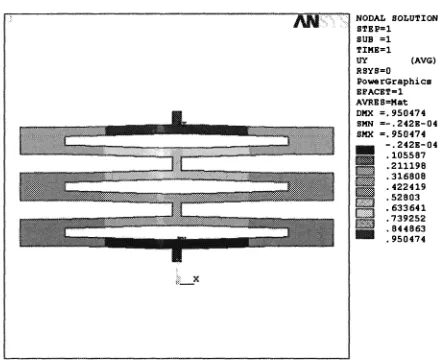
box spring. One of the resultsof the
spring distortion undera
forceis
shownin
Fig. 1.
From Table 1,
we can see thatthe
theoreticalapproximations and ANSYS results
are
closein
value.TABLE 1. Results
of
'box' spring constantk
using ANSYS static analysisApplied force (jtN) Maximum Displacement
(im) Spring constant
k
(jiN/jim)50 1.015 49.2611
100 2.03 49.2611
150 3.046 49.2499
200 4.061 49.2490
250 5.076 49.25 14
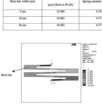
In
orderto
analysis the effectof the
short bars, we changethe
widthof
the shortbar
and analysethe
box springsagain using ANSYS. A series ofvalues ofshort bars that were analysed
is
shownin
Table2.
One ofANSYS resultsis
shownin
Fig. 3.TABLE 2. Results ofdifferent wide
of
barsShort
bar
width (pm) Maximum Displacement(jim) (force
is
50 siN) Spring constantk
Q.tN/pm)2 1.015 49.26
3 0.971662 51.46
4 0.954371 52.39
5 0.951012 52.58
10 0.950474 52.61
NODAL SOLUTION
STEP1 SUB 1
TIME1
UY (AVG)
R5Y50
PowerGraphics
EFACET1
AVRES=Mat
DMX . 950474
SMN =— . 2425-04 SMX . 950474
— .2425—04 . 105507
:.' .211198 .316808
•.•: •
422419
.52803
—
633641. . 739252 . 844863 . 950474
Fig. 3. One ofresults from ANSYS, where
the
short bar widthis
10 Itm.2.
'zig-zag' spring
in-plane distortion
Another spring that has been analysed
is
called 'zig-zag' spring. This typeof
spring containsa
numbersof
bars connectedin
a
'zig-zag' path.A
beam model has been constructed for analysingin
ANSYS software.In
this model, one endofthis
springis
fixed andat
the other enda
series offorcesare
applied anda
series ofdisplacement results are obtained as shownin
Table 3. The spring constantk
is
calculated as before. The force directionis
alongthe
y-axis as shown
in
Fig.4.
It
is
noticed that together with the extensionin the
y-direction, thereis
a
small distortionof
the
structurein the
x-direction. The unbalanceofthe
spring appearsin
Figure 5. The reasonis
the short bar betweentwo long bars also bends when the force
is
applied.TABLE 3. Results
of
'zig-zag' spring constantk
using ANSYS static analysisApplied force
(tN)
Maximum Displacement(im)
Spring constantk
QxN/xm)50 11.489 4.3520
100 22.978 4.3520
150 34.467 4.3520
200 45.956 4.3520
250 57.445 4.3520
... .
[image:5.612.195.414.76.256.2]ANSYS 5.7.1
-
. 57764—
.7630992.104
3445
4.785 6.126 7.467
£3
8.80810.148 11.489
ANSYS 5.7.1
—
. 103553 .207106.310659
:3 .414212
.517764 .621317
£3 .72487
[image:6.612.156.420.79.295.2].828423 .931976
Fig. 5. ANSYS analysis
of
'zig-zag' spring,the
force F=5OuN. The result showsthe
x-axis displacement. The numbers (urn)on the
leftofthe
figure represented the [image:6.612.173.429.364.576.2]displacement value.
Fig. 4. ANSYS analysis
ot
'zig-zag' spring, the force F=5OuN. The result showsthe
y-axis displacement. The numbers (um)on the
leftofthe
figure represented thedisplacement value.
____
j
F
rIIii
-
The zig-zag spring has been analyzed
in the
same wayas the
box spring. Table4
showsthe
spring constantcalculated from
the
ANSYS static analysis. Fig6
shows one example ofan ANSYS result. The short bar widthis
20pm.
TABLE 4. Results ofdifferent width ofbars for zig-zag spring
NODAL SOLUTION
STEP1
SUB 1 TIME1
UY (AVG)
RSYSO
PowerGraphics EFACET1 AVRESMat DNX 10.4B3
SMX 10.482
!!
1.165,..., 2.329 6.2 4.659 ... 5.823
6.988
L! 8.153 9.317
10.482
Short
bar
width (urn) Maximum Displacement(.tm) (force
is
50 uN)Spring constant
k
(j.tN/pm)5um 10.504 4.76
lOum 10.482 4.77
2Oum 10.482 4.77
Short bar
AN
Fig.
6.
One ofresults from ANSYS, wherethe
shortbar
widthis
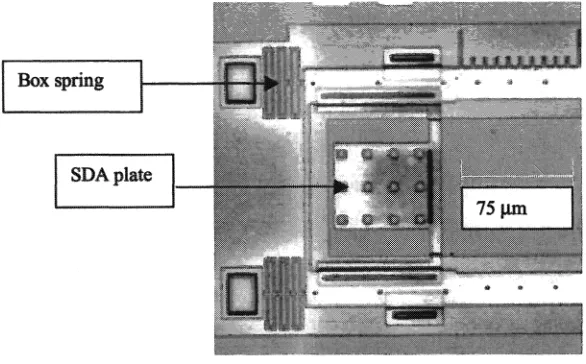
20 jim.3. Scratch drive actuator force
analysis
Four different designs
of
SDAs have been fabricated. They have from 1to
4
plates with two 'box' springs. They [image:7.612.104.440.188.533.2]voltage
is
appliedto
SDA,it
moves forward and stretchesthe
spring. The stretch canbe
measured fromthe
scale.Once
the
SDA's force equalsthe
spring's restoration force, the system achievesa
balance andthe
SDA will stop.Thus, using this displacement and the spring constant
k
we can calculatethe
force thatthe
SDA generates.In
this design,the
spring constant ofthe box-springis
49.3jsN/m (by ANSYS) and 51.3N/jim
(by theoretical). Sothe
valueof
5OjxN/j.tm willbe
usedto
calculatethe
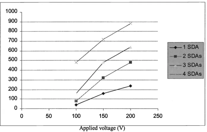
spring restoration force. Different voltages from 100-200V havebeen applied
to
the
SDA. The frequencyis
constant and hasa
valueof
100Hz. Fig. 8 showsthe
results ofthe SDAs' forces for different voltage conditions.At
the same time, 2-plate, 3-plate, and 4-plate SDAs also have beeninvestigated by
the
same method. The results show that increasingthe
SDA plates generates more force, but the force does not increase linearly withthe
numberof
plates.,
.
-
•:
uLfsuJ;
i3ox spring
ass
sDAlz:m1
I
i_J
S
f
Uk
Fig. 7. Photograph
of
scratch drive actuator [image:8.612.126.419.355.537.2]1000 900 800 700 600 500
400
300 200 100 0
,7
____a
Force QtN) I
*2
SDASI3SOAs
4
SDM0 50 100 150 200 250
[image:9.612.153.502.65.288.2]Applied voltage (V)
Fig. 8. Forces
of
single SDA, 2-stage SDA, 3-stage SDA and 4-stage SDA whileapplied different voltage.
4,
Conclusion
Two types
of
microsprings have been analysedby
FEM using ANSYS.For the
'box' spring,the
results fromANSYS and from mechanical theory
are
very close. We also call this typeof
spring 'balanced' spring, becausewhen applying force only
in
y
direction, the displacement occurs onlyin
y
direction. Onthe
contrary, the so called'zig-zag' spring
is not
balanced when applying single central forceto
it. Some scratch drive actuators with boxsprings have been fabricated using the MUMPs process. These 5DM have been experimentally analysed
to
indicatetheir force properties. Forces of250
iN
for one plate SDA, 900 j.tN for4
plate SDAs have been estimated.References:
[1]. Hiroyuki Fujita, "Microactuators and Micromachines," Proceedings ofThe IEEE, Vol. 86, No. 8, August 1998,
pp. 172 1-1998.
[2]. Terunobu Akiyama and Katsufusa Shono, "Controlled Stepwise Motion
in
Polysilicon Microstructures," Journal ofMicroelectromechanical Systems, Vol. 2, No.3,
September 1993, pp.106-110.[3]. David A. Koester, Ramaswamy Mahadevan, Buzz Hardy and Karen W. Markus,