A novel Hemi-Body Irradiation technique using electron beams (HBIe-)
Authors
Panagiotis Delinikolas1, 2,*, Georgios Patatoukas1, Vasilios Kouloulias1, Maria Dilvoi1, Agapi Plousi1, Efstathios Efstathopoulos1,Kalliopi Platoni1
12nd Department of Radiology, Radiotherapy Unit, ATTIKON Hospital, University of Athens School of Medicine, Greece
2Space Radiobiology Research, Physics Department, Strathclyde University, Glasgow, UK
* Corresponding Author
Panagiotis Delinikolas
Office 7.24, John Anderson Building (Physics), Strathclyde University 107 Rottenrow East, G40NG, Glasgow, Scotland, United Kingdom Email: [email protected]
Mob: +447498506591
1 Abstract
Purpose
Certain radiation responsive skin diseases may develop symptoms on the upper or the lower half of the body. The concept of a novel Hemi-Body Electron Irradiation (HBIe-) technique, described in this work, provides a low cost, LINAC based, intermediate treatment option in between extremely localized and Total Skin irradiation techniques.
Materials and Methods
The HBIe- technique, developed in our department, incorporates a custom crafted treatment chamber equipped with adjustable Pb shielding and a single electron beam in extended Source-Skin Distance (SSD) setup. The patient is conceptually positioned in custom 'Stanford' technique positions. The geometrical setup provides both optimal dose homogeneity and dose deposition up to a depth of 2 cm. To confirm this, the following characteristics were measured and evaluated: a) percentage depth dose (PDD) on the treatment plane produced by a single electron beam at perpendicular incidence for six fields at 'Stanford' angles, b) 2D profile of the entrance dose on the treatment plane produced by a single field and c) the total surface dose on an anthropomorphic phantom delivered by all 6 fields.
Results
The resulting homogeneity of the surface dose in the treatment plane for an average patient was 5-6%, while surface dose homogeneity on the anthropomorphic phantom was 7% for both the upper and the lower HBIe- variants. The total PDD exhibits an almost linear decrease to a practical range of 2 g/cm2.
Conclusion
2 Introduction
Certain radiation responsive skin diseases, such as Kaposi’s sarcoma (KS), mycosis fungoides (MF) and Sézary syndrome (SS), may develop symptoms on the upper or the lower half of the body. KS, in its epidemic form, is frequently present in patients with a prior infection of HIV-1 retrovirus [HIV-1-3]. Most common irradiation techniques for KS either involve schemes of 20 Gy in 5 fractions or 24 Gy in 12 fractions [4-7], producing similar responses and toxicities. For small areas of occurrence, treatment of the superficial targets can be performed with x-rays using VMAT techniques [1] or via brachytherapy using surface applicators [8], while for large areas, electron beams are preferable due to the short range of electrons which produces less total body dose. In particular, electron therapies involve either a number of localized fields or extensive irradiation by the use of the Total Skin Electron Beam technique (TSEB). Cutaneous T cell non-Hodgkin lymphoma is a rare lymphoproliferative disease with continuously aggravating reoccurrence, of which MF and SS are derivative diseases. Localized irradiation can cure "minimal stage" MF while TSEB may cure early-stage disease or offer important symptom relief (itch, erythroderma) in a more advanced setting [9]. Although radiation therapy seems to produce good clinical response, it is not widely used, mainly due to technical difficulties in the production of large fields.
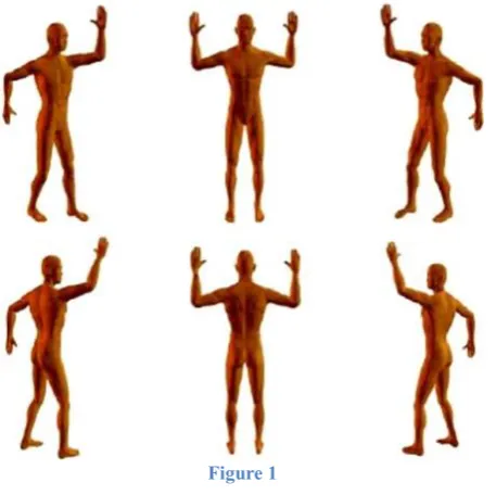
TSEB is a curatively or palliatively administered therapy for skin diseases such as KS, MF, SS and inflammatory breast cancer [10,11]. Depending on the variant of the TSEB treatment technique, the patient is either positioned at several pre-defined standing positions (Stanford Technique [12] presented in Figure 1, where the patient takes positions at angles of 0, 60,120,180,240 and 300 degrees with respect to the treatment plane), or rotating during irradiation on a base at a constant angular speed, or lying on a motor driven couch which is translated through the large electron field [13,14]. The objective of TSEB is to deliver a uniform dose to the skin using electron beams, with an acceptable variation of dose distribution (±8% vertically and ±4% horizontally within the central 160 cm × 60 cm field area according to AAPM Report No.23 [13]). Nowadays, TSEB techniques have become increasingly optimized, providing acceptable dose distributions, while the dose at cold-spots is enhanced by boost fields [15]. TSEB sessions deliver the prescribed dose of 32-40 Gy to the patient’s skin without damaging organs at risk [16]. Electrons with energies of 4-8 MeV have been proven to provide the appropriate therapeutic range, while the main toxicities are dry epidermitis with limited frequency of skin ulcerations [17]. The TSEB technique implementation at the Radiation Therapy Unit of University General Hospital “Attikon” has been described extensively by Platoni K. et al. [15]. Six dual fields of 6 MeV electron beams at nominal SSD=3.8 m are combined with the ‘Stanford’ patient’s standing positions (Figure 1) to deliver the prescribed dose to the skin. As shown in Figure 2, the patients’ immobilization system and a plexiglass slab (for the appropriate degrading of the beam’s mean energy and widening of the fields) were fitted in a custom built chamber.
Current half body irradiation techniques are used mainly for palliative purposes in metastatic diseases (prostate, lung and breast cancers) and involve photons as source of radiation [18-26]. In most of the cases, x-rays produced by linacs, γ rays produced by Cobalt Units [22] and even UVB rays, in phototherapy studies [24,] were utilized, yet only for highly palliative treatments in patients with a very short life expectancy (bony metastatic cancer [5,22,23], acute leukemia [25], metastatic carcinoma of the prostate [26]). The described photon HBI techniques are not suitable for cases with better prognosis, due to the large volumes of the patients’ body being irradiated by lower dose.
3
HBI techniques do not apply electron beams, which can be very efficient in cases of such radiation responsive skin disorders. Additionally, a half body electron irradiation technique can reduce treatment time in comparison to TSEB techniques, which require longer implementation time. In this work the development of a novel electron beam HBI treatment is presented, given the current background of techniques implied both in HBI and TSEB sessions. Treatment setup, electron beam measurements and TLD dosimetry for the implementation of HBIe- in “Attikon” Hospital (Athens Greece) were performed and described in accordance to TRS 398 dosimetric protocol of IAEA [27] and to No.23 AAPM Report [13]. All methods of implementation and final proposals are based upon the currently available equipment in our department.
Materials and Methods
Materials
A Varian 2100C linear accelerator (Varian Medical Systems Inc, Palo Alto CA USA)was used to produce 6 MeV electron beams with a field size of 36 x 36 cm2, delivered at the high dose rate of 2500MU/min at the isocenter. This mode was selected to minimize the treatment time and optimize coverage of target area in an extended SSD setup.
The custom made chamber of our department, used for TSEB treatment (Figure 2), was also utilized for HBIe-, providing appropriate conditions for skin irradiation (energy degradation of nominal 6 MeV electron beams and field size widening through scattering and patient positioning).
Electron beam measurements were performed using Roos® and Markus® plane parallel ionization chambers and a PTW Unidos® Universal Dosimeter (PTW Freiburg GmbH, Germany). Measurements in the treatment plane were performed with a PTW PMMA slab phantom, while for absolute dose measurements (quality check of the beam) in water, a PTW-MP3 tank phantom was used.
For the dose distribution measurements on patient’s skin, TLD dosimetry was performed with Thermo Scientific TLDs 100-H (LiF:Mg,Cu,P) chips on an anthropomorphic Rando® Alderson phantom. Calibration, annealing and TLD signal reading procedures were performed using a LTM Manual TLD Reader and a Fimel ETT Oven (Fimel, Velizy, France).
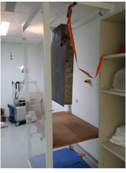
To reduce the noise in the ionization chambers’ signal, a custom made cable shielding was used in conjunction with all the ionization chambers. For the Lower HBIe- case, a custom made universal shielding2 mm Pb thick (Figure 3) was attached to the treatment chamber and a second one was designed for the Upper HBIe- case. Any additional shielding for sensitive areas and/or organs at risk (eyes, nails, genitalia etc.) should be designed for each patient individually.
4 Methods
The implemented method of HBIe- incorporated a single electron beam and the custom TSEB chamber of our department with a standard isocenter to Plexiglas distance of 250 cm. The distance from the Plexiglas window edge (0.5 cm thick [15]) to the treatment plane was 30 cm for both Upper and Thoracic HBIe- (Thoracic HBIe- is a variant of Upper HBIe- with a patient’s head shielded), while for the Lower HBIe- it was 38 cm. The setup was chosen given that:
• All other possible setups were rejected either due to field projections not covering adequately the target area or due to the lack of the appropriate equipment (e.g. Electron Arc therapy module).
• The practical range of the electron beam on the treatment plane was measured at 2 cm and thus considered suitable for skin treatment applications.
• The projected field size from a single beam was large enough to cover half of the body (either the upper or the lower half), while the remaining half of the body was protected from being directly irradiated from the LINAC source. For maximum protection from scatter components (electrons scattered in air and Plexiglas) and from high skin dose gradients at the borders of the target, the universal shielding (Figure 3) had been developed.
• Homogeneity of the surface dose at the treatment plane with variation of 2 and 4 % at the longitudinal and horizontal axes was taken from a previous study conducted in our department (Platoni et al. [15)].
• The difference of 8 cm in the SSD for the Upper and Lower HBIe- was chosen by considering the dimensions of the high dose area near CAX (see Results section and Figure 7). For the Upper HBIe- the SSD was selected to be smaller than in Lower HBIe -in order to m-inimize the presence of dose hot spots on patient.
The patient standing technique was chosen to be a variation of the “Stanford” technique, during which the patient aligns only the upper or the lower half of his body depending on the mode of the HBIe- treatment. The steps for the development and dosimetry in HBIe- were as follows:
1. The energy at the treatment plane of a single beam incident with its central axis orthogonal to the treatment plane (Gantry angle at 270 degrees) at SSD of 380 cm was calculated from the characteristics of the percentage depth dose (PDD) curve (such as mean electron beam energy, most probable energy and electron ranges). Since practically there is no impact on the PDD if the SSD was 388 cm [13], the energy at treatment plane after the Plexiglass attenuation is the same both for Upper and Lower HBIe-. In addition, electron beam absolute dosimetry in standard reference conditions (SSD=100 cm, Gantry=0 degrees for 6 MeV) was performed using the water tank phantom.
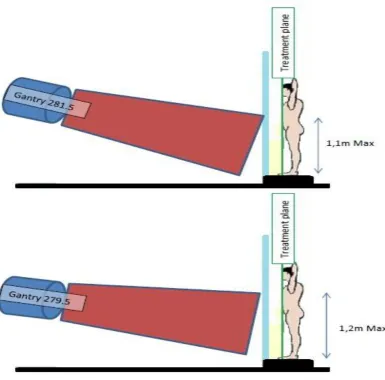
2. The gantry angle providing the best geometrical coverage and protection of patient with the optimal homogeneity of surface dose in treatment plane was identified in this step. For five different beam angles for Upper and Lower HBIe- (Figure 5), the electric charge using an ionization chamber was measured at 60 evenly distributed points at the treatment plane. For each point, the measurement was repeated three times using a PMMA slab phantom and Markus® ionization chamber. The angles producing the lowest Coefficient of Variation (C.V.=std/average) of the readings were selected as the most suitable for clinical use.
5
PDD curve. The results of the individual PDD curves were then compared to the measurements acquired for the selected (from step 2) gantry angles for Upper and Lower HBIe- at a depth of 6 mm in PMMA for the same 6 incidence angles.
4. Since for the case of the Upper HBIe- the CAX was on the patient’s chest or abdomen (depending on the patient’s dimensions), the calibration point was defined at the intersection of the CAX with the patient’s skin. For Lower HBIe- a different approach for the dose calibration had to be adopted in order to overcome the lack of tissue between the patient’s legs, where the CAX of the beam was pointing. The single calibration point was transformed into a dual calibration point located on patient’s legs and designated by the appropriate targeting tool.
5. Monitor Units (MU) were calculated from the measurements of the surface dose per MU per field at the calibration point of each HBIe- variant. For the Lower HBIe- the surface dose was given at the intersection of CAX with the treatment plane and it was then corrected for the new selected dual calibration point. That was achieved by correcting the surface dose of CAX to the mean surface dose of the 2 points (by which the dual calibration point was defined).
6. Verification of the technique was performed by TLD dosimetry on an anthropomorphic phantom. Two TLD calibration procedures were performed, one under standard reference conditions (SSD=100cm and gantry angle at 0 degrees) and one under HBIe -treatment conditions (SSD=380 cm and gantry=270 degrees) with the TLD mounting plate on surface of the PMMA phantom and covered with plain paper and tape. Finally, TLD dosimetry for the actual dose distribution was performed on an anthropomorphic phantom for Upper and Lower HBIe- treatments.
Results
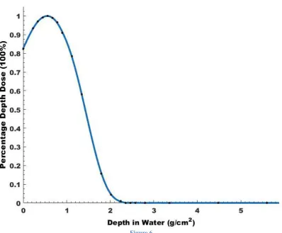
Figure 6 shows the PDD curve at the extended SSD of 380 cm with the gantry angle set at 270 degrees (as described at step 1 in the Methods section). Given that the curve’s zmax=0.56 g/cm2 and Rp=1.91 g/cm2, the most probable energy of Ep,o=4 MeV was deduced.
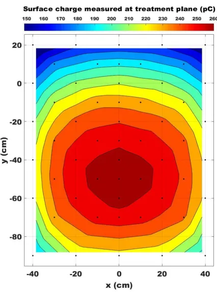
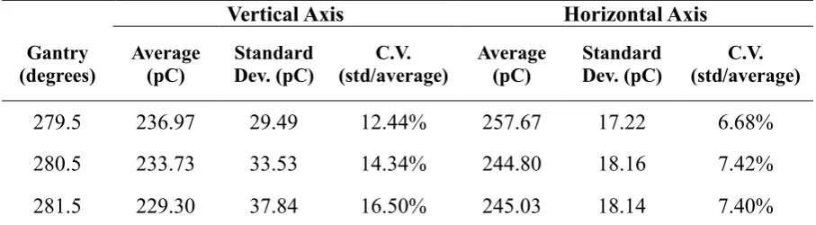
For the Upper (and the Thoracic) HBIe- treatment, the homogeneity results, for the vertical and horizontal axes of the treatment plane, are presented in Table 1. Due to the increased homogeneity exhibited, the gantry irradiation angle of 262.5° was selected for the Upper HBIe -treatment. The total C.V. of the whole treatment plane area was 16.4% referring to patient upper body dimensions of 120 x 80 cm2. For the average adult with height 1.70 cm and weight 75 kg, due to the central coverage of the treatment plane, the respective C.V. on the patient drops to 5.9%. For the Lower HBIe- treatment the respective results are presented in Table 2. The angle selected was that of 279.5 agrees which yielded a total C.V. in the treatment plane of 14.2%. As a representation of dose homogeneity in the treatment plane (two-dimensional profile of surface dose), Figure 7 shows the distribution of charge measured by the Markus chamber at the front (vertical) surface of a PMMA phantom placed at SSD=388 cm at 279.5° gantry angle. The beam CAX intersects the phantom at the point x=0, y=-50, while x=0, y=0 is the intersection at gantry angle 270°. The on-patient C.V. drops to 4.9% for the average adult dimensions by the implementation of the targeting tool (Figure 4), which practically does not allow any part of the patient to be present in the central high dose area.
6
The beam characteristics for the total treatment in comparison with the single field (beam axis vertical to the surface of the phantom) are presented in Table 3.
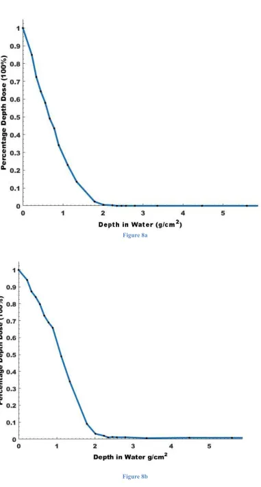
Additionally, the dose at zref=0.46 cm in water produced by all 6 fields (irradiation with 100 MU per field) was calculated. By using the total PDD in water (Figure 8b), it was estimated that the percentage depth dose at zref was close to 84% while on surface was 100%, which means that a factor of 1.19 is needed to derive the entry dose from the dose at zref. Finally, by dividing the entry dose with the number of MU per field (as mentioned 100 MU per field), the entry dose per MU per field (D𝑧=0(6p)) was extracted:
D𝑧=0(6p)= 0.0038 𝐺𝑦𝑀𝑈 𝐹𝑖𝑒𝑙𝑑
Equation 1
This means that if one irradiates with 1MU per each field the entry dose on the patient’s skin will be 0.38cGy. The dose per MU, both at the surface and at a treatment depth of z=0.6 cm varies slightly with gantry angle, but only to an extent which can be neglected in clinical practice. For a gantry angle of 279.5°, the surface dose at the CAX intersection point (x=0, y=-50) was 1.25% greater and the dose at z=0.6cm depth was 4.4% less than the respective doses for gantry angle 270° at x=0, y=0. Since dose prescription in HBIe- is usually referred to at the skin surface (e.g. in order to allow confirmation with in-vivo dosimetry), the difference of 1.25% should be corrected. On the other hand, the dose at zref, R90 or R85 (as measured for 270° gantry angle) was estimated to decrease close to 2% when shifting the gantry angle by 9.5°, compensating much of the dose difference at the surface. Therefore, a dose prescription at these depths could use the same dose/MU relation for both gantry angles (270 and 279.5 degrees). The situation is similar for a gantry angle of 262.5° in Lower HBIe-. For this case, the charge/MU was compared between gantry angles of 279.5° and 262.5°. Due to difference of only 2 degrees in the deviation from the reference angle of 270°, differences in the PDDs Upper and lower HBI are expected to be negligible. Surface dose per MU at 262.5° was 1% greater than at 270°, so that dose prescription can be performed with the same procedure for both upper and lower HBI.
Lower HBIe- MU calculation
Initial MU calculation was performed for gantry angle 270 degrees for the total therapy (6 fields). Given that the dose prescription refers to the surface of the skin, MUs per field were given by the following relation:
𝑀𝑈270= 𝐷𝑓 𝐷𝑧=0(6𝑝)(
𝑀𝑈 𝑓𝑖𝑒𝑙𝑑) Equation 2
Where, Df represents the prescribed dose per fraction, while 𝐷𝑧=0(6𝑝) is given by equation 1. For gantry angle of 279.5 degrees, surface dose increases by 1.25% (CAX at x=0, y=-50), so the monitor units should be decreased by a correction factor of 0.9875 (𝐹𝐿𝐻𝐵𝐼𝑒𝐴𝑛𝑔𝑙𝑒). Due to calibration points positions (y=-40, x=20 and x=-20) there was a decrease in surface dose of almost 4.4% in average, so the second correction was to increase the MU/field by 1.043 (𝐹𝐿𝐻𝐵𝐼𝑒𝐶𝑎𝑙𝑖𝑏.). So finally:
7 Upper HBIe- MU calculation
Since the calibration point is on treatment plane along CAX, the only correction needed was to decrease MU270 by a correction factor of 0.99 (𝐹𝑈𝐻𝐵𝐼𝑒𝐴𝑛𝑔𝑙𝑒) in order to balance the surface dose increase (1%) due to gantry angle of 262.5 degrees.
𝑀𝑈𝑈𝑝𝑝𝑒𝑟𝐻𝐵𝐼𝑒= 𝑀𝑈270∗ 𝐹𝑈𝐻𝐵𝐼𝑒𝐴𝑛𝑔𝑙𝑒( 𝑀𝑈 𝑓𝑖𝑒𝑙𝑑) Equation 4
The average difference in the measured dose for the 2 TLD calibration methods (one in reference conditions at SSD=100 cm and one for the extended SSD=388cm of HBIe- ) was approximately 4-5% for a range of doses from 0.2 Gy to 3.5 Gy (larger dose values were observed for the calibration in reference conditions). The extended SSD calibration was chosen due to the accurate reproduction of the conditions while in HBIe- setup.
Results of TLD dosimetry on the anthropomorphic phantom for Upper (and Thoracic) HBIe -are presented in Figure 9. The dose per fraction was set to 2 Gy at the surface and the monitor units used were calculated from equation 4. The measured average dose was 1.97 Gy with a C.V. of 7%. Dose measurements from the back side of the phantom were included. Results of the performed TLD dosimetry on the anthropomorphic phantom for Lower HBIe- are presented in Figure 10. The prescribed dose per fraction was set at 2 Gy on the skin and the monitor units used were calculated from equation 3.For Lower HBIe- the average dose was 1.99 Gy with a C.V. of 9.7%. In this calculation the doses measured with TLDs placed on the back of the phantom were also included.
Discussion
Depth dose distribution
As presented in the results section, the average energy on treatment plane was approximately 3.2 MeV and the most probable energy was 4 MeV. Due to the positioning of the patient (or phantom) in order to generate a combined depth dose curve from all 6 beams applied to the patient (or phantom), the depth dose distributions of each beam (6 fields in total) were added for the same depth resulting in a PDD curve at equal depths. Just below surface the dose decreases almost linearly and the range of the combined 6 fields was found similar to practical range produced by a single field (1.91 g/cm2 in water). That was expected, since the field at vertical phantom incidence (patient/phantom position at 0 degrees) was the one to define the practical range of the produced PDD by the 6 fields, rather than the two angled incidence fields (larger incidence angle causes more superficial dose deposition – see also Figures 6 and 8a). The R50 value in water for the 6 fields (R50=0.93 cm) is in line with AAPM report no.23 [13] recommendations.
8
(refer to results), it should be commented that the percentage depth dose in zref and its neighbors R90 and R85 was assumed to suffer a 2% drop, for the 9.5 or 7.5 degrees differences in gantry angle (in comparison to gantry angle 270 degrees case), while the absolute dose at these points remained practically unchanged.
In the past few years the development of novel radiation techniques such as volumetric modulated arc therapy have led to the implementation of new methods for treating patients with skin disease. There is a limited number of studies published in the literature that test the effectiveness of such modern treatment techniques and moreover they are usually applied to limited areas of occurrence [1At this point, these studies present patient-specific cases and cannot be considered as yet for the extraction of generalized conclusions.
Bremsstrahlung Contamination
Bremsstrahlung contamination for the total of 6 fields in HBIe- was calculated based upon the PDD summation to be 0.7%. As an example, for a prescribed surface dose of 32 Gy (total prescription), only 24.64 cGy will be deposited at depths larger than 3cm from the surface. As mentioned in the methods, Bremsstrahlung intensity is greater near the CAX of the beam.. In Upper HBIe- there is no way to decrease the aforementioned contribution of 0.7% but in Lower HBIe-, using the positioning tool (Figure 4), which ensures that no parts of the patient are located in central high dose area, a further reduction of bremsstrahlung dose to the patient is possible. Before every treatment session of Lower HBIe- the positioning tool should be placed in a predefined position on the floor of the treatment chamber (the circular front surface aligned to match with the treatment plane and centered so that the vertical beam targeting laser perfectly divides the disc in half). Following alignment, the circular surface designates the central high dose area of Figure 7 and the dual calibration points on patient’s legs (see methods and results sections). The patient’s legs for each Stanford position should just about touch the borders of the disc and not overlap with it. That will ensure that the patient is clear from high dose areas, while minimizing Bremsstrahlung contribution.
Surface Dose Homogeneity on treatment plane
In both Upper and Lower HBIe- (see also Figure 7) for the 80% of target area dimensions (patient maximum dimensions end-to-end.:120 x 80 cm2), a horizontal and vertical C.V. of 6% and 3% respectively were observed in the surface dose distribution. These results meet the criteria set by the guidelines for TSEB [13].
Surface Dose Homogeneity on Anthropomorphic Phantom
9
almost identical with the prescribed dose for both techniques (Upper and Lower HBIe-) – yielding a 1.5% difference. In addition, the homogeneity index (C.V.) of the Upper HBIe- treatment dose distribution was 7% for the total 6 single fields. For TSEB sessions of the similar setup and in vivo dosimetry (6 dual-fields with scatter) the TLD measurements homogeneity was 15.4% for 67 cases [29]. Lower HBIe-produces a greater C.V. and that is mainly due to the limited area on which readings were taken due to phantom size limitations.
Patient Shielding
Certain areas of the body must be protected during HBIe- treatments, depending on the type of HBIe-technique. For instance, in Lower HBIe-, the universal shielding (made of Pb with 2 mm thickness for less than 5% transmission) can effectively protect the relevant organs at risk such as the eyes, the lips, the hand nails, the thyroid gland etc., while additional shielding for the genitalia and the toes’ nails is needed. TLD dosimetry must be performed during the first two or three fractions (and then periodically) in HBIe- for the organs at risk protected by the universal shielding and custom shielding, in order to dosimetrically confirm the effectiveness of protection in terms of dose distribution. Additional custom shielding must be implemented by case. For such cases, if extra shielding is needed, 4mm of Pb should provide adequate shielding.
Boost Fields
If clinically indicated, low dose regions and soles (in case of Lower HBIe-) should be irradiated by follow up boost fields, in order to improve dose homogeneity.
Conclusions
The HBIe- techniques presented in this work have managed to successfully deposit the prescribed dose in the portion of the skin which needed treatment, whilst reducing the dose to the unaffected skin areas significantly. Moreover, due to the relatively low cost of the materials used, the proposed technique can be easily and straightforwardly implemented in clinics equipped with medical accelerators capable of producing 6 MeV electron beams and adequate space for extended SDD setup. All three HBIe- variants (Upper, Lower and Thoracic) presented in this study aim to enable practitioners to deliver more optimized treatment for each clinical case.
It would be of much interest to investigate if total skin therapy can take advantage of the new radiation therapy techniques such as VMAT in terms of time efficiency, dose accuracy and comfort patient positioning.
Disclosure of Conflict
10 References
1. Nicolini G, Abraham S, Fogliata A, Jordaan A, Clivio A, Vanetti E, Cozzi L. “Critical appraisal of volumetric-modulated arc therapy compared with electrons for the radiotherapy of cutaneous Kaposi’s sarcoma of lower Extremities with bone sparing.”Br J Radiol. Vol 86 issue 1023,2013.
2. Frank Richter MD, George J. Hill MD & Robert A. Schwartz MD “Professor Kaposi's original concepts of Kaposi's sarcoma.”J Cancer Educ. 10(2), 1995, pp.113-6.
3. Kaposi M “Idiopathisches multiples Pigmentsarkom der Haut.” Arch f. Dermatol u Syph Vol 4, 1872, pp.265-73.
4. Singh NB, Lakier RH, Donde B“Hypofractionated radiation therapy in the treatment of epidemic Kaposi sarcoma--a prospective randomized trial.”Radiother Oncol. 88(2), 2008, pp.211-6.
5. Berg RS, Yilmaz MK, Høyer M, Keldsen N, Nielsen OS, Ewertz M “Half body irradiation of patients with multiple bone metastases: a phase II trial.” Acta Oncol. 48(4), 2009, pp.556-61.
6. Stein ME, Lachter J, Spencer D, Margolius L, Bezwoda WR “Variants of Kaposi's sarcoma in Southern Africa. A retrospective analysis (1980-1992).”Acta Oncol. 35(2), 1996, pp.193-9.
7. Conill C, Alsina M, Verger E, Henríquez I “Radiation therapy in AIDS-related cutaneous Kaposi's sarcoma.”Dermatology, 195(1), 1997, pp.40-2.
8. Evans MD, Yassa M, Podgorsak EB, Roman TN, Schreiner LJ, Souhami L “Surface applicators for high dose rate brachytherapy in AIDS-related Kaposi's sarcoma.” Int J Radiat Oncol Biol Phys. 39(3), 1997, pp.769-74.
9. Mazzeo E, Rubino L, Buglione M, Antognoni P, Magrini SM, Bertoni F, Parmiggiani M, Barbieri P, Bertoni F “The current management of mycosis fungoides and Sézary syndrome and the role of radiotherapy: Principles and indications.”Rep Pract Oncol Radiother. 19(2), 2013, pp.77-91.
10. G.W. Jones, D. Rosenthal, L.D. Wilson “Total skin electron radiation for patients with erythrodermic cutaneous T-cell lymphoma (mycosis fungoides and the Sezary syndrome)” Cancer 85 (9), 1999, pp.1985–1995.
11. A. Funk, F. Hensley, R. Krempien, D. Neuhof, M. Van Kampen, M. Treiber, et al. “Palliative total skin electron beam therapy (TSEBT) for advanced cutaneous T-cell lymphoma.” Eur J Dermatol, 18 (3), 2008, pp. 308–312.
12. T Piotrowski, P Milecki, M Skórska, D Fundowicz. “Total skin electron irradiation techniques: a review.” Postepy Dermatol Alergol. 30(1), 2013, pp.50–55.
11
14. “Radiation Oncology Physics: A handbook for teachers and students.”, IAEA, 2005.
15. Platoni K, Diamantopoulos S, Panayiotakis G, Kouloulias V, Pantelakos P, Kelekis N, Efstathopoulos E ”First application of total skin electron beam irradiation in Greece: setup, measurements and dosimetry.” Phys Med. 28(2), 2012, pp.174-82.
16. Diamantopoulos S., Platoni K, Dilvoi M, Nazos I, Geropantas K, Maravelis G, Tolia M, Beli I, Efstathopoulos E, Pantelakos P, Panayiotakis G, Kouloulias V. “Clinical implementation of total skin electron beam (TSEB) therapy: a review of the relevant literature.”Phys Med. 27(2), 2011, pp.62-8.
17. Geara F, Le Bourgeois JP, Piedbois P, Pavlovitch JM, Mazeron JJ “Radiotherapy in the management of cutaneous epidemic Kaposi's sarcoma.” Geara F1, Le Bourgeois JP, Piedbois P, Pavlovitch JM, Mazeron JJ. Int J Radiat Oncol Biol Phys. 21(6), 1991, pp.1517-22.
18. Vakaet LA, Boterberg T “Pain control by ionizing radiation of bone metastasis.” Int J Dev Biol. 48(5-6), 2004,pp.599-606.
19. Pal S, Dutta S, Adhikary SS, Bhattacharya B, Ghosh B, Patra NB “Hemi body irradiation: An economical way of palliation of pain in bone metastasis in advanced cancer.” South Asian J Cancer. 3(1), 2014, pp.28-32.
20. Furlan C, Trovo M, Drigo A, Capra E, Trovo MG “Half-Body Irradiation With Tomotherapy for Pain Palliation in Metastatic Breast Cancer.”, J Pain Symptom Manage. 47(1), 2014, pp.174-80.
21. Ma S, Richardson JA, Bitmansour A, Solberg TD, Pidikiti R, Song K, Stojadinovic S, Vitetta ES, Meyer JJ “Partial Depletion of Regulatory T Cells Does Not Influence the Inflammation Caused by High Dose Hemi-Body Irradiation.” PLoS One. 8(2), 2013.
22. Pal S, Dutta S, Adhikary SS, Bhattacharya B, Ghosh B, Patra NB. “Hemi body irradiation: An economical way of palliation of pain in bone metastasis in advanced cancer.” South Asian J Cancer. 3(1), 2014, pp.28-32.
23. Biswal BM. J Indian “Assessment of the usefulness of hemibody irradiation in painful bone metastasis.” Med Assoc. 102(3), 2004, pp.133-4, pp.136-7.
24. Chel VG, Ooms ME, Pavel S, de Gruijl F, Brand A, Lips P “Prevention and treatment of vitamin D deficiency in Dutch psychogeriatric nursing home residents by weekly half-body UVB exposure after showering: a pilot study.”Age Ageing. 40(2), 2011, pp.211-4.
25. Mao Y, You Y, Chu J, Zhu H, Yan W “Alternative hemi-body irradiation in acute leukemia and malignant lymphoma.”Chin Med J (Engl). 112(11), 1999 pp.1054-5.
26. Bashir FA, Parry JM, Windsor PM “Use of a modified hemi-body irradiation technique for metastatic carcinoma of the prostate: report of a 10-year experience.”Clin Oncol (R Coll Radiol)20(8), 2008 Oct, pp. 591-8.
12
28. Saw CB1, Pawlicki T, Korb LJ, Wu A “Effects of extended SSD on electron-beam depth-dose curves.” Med Dosim. 19(2), 1994, pp.77-81.
13 Figures
Figure 1
[image:14.595.201.430.134.362.2]14
[image:15.595.198.406.79.364.2]Figure 3
15
16
17
18
Figure 8a
19
20
[image:21.595.79.517.97.750.2]21 Figure Captions
Figure 1-Patient positioning in “Stanford technique” [12].
Figure 2- Custom Built TSEB Chamber - Radiotherapy Division Attikon University Hospital, Greece [15].
Figure 3 – Custom made universal shielding for Lower HBIe- mounted with straps (orange) in the treatment chamber.
Figure 4 - Custom Lower HBIe- patient positioning tool. It is meant to be used only in Lower HBIe- treatment sessions and it is placed in a predefined position on the floor of the treatment chamber (the circular front surface aligned to match with the treatment plane and centered so that the vertical beam targeting laser perfectly divides the disc in half). Since aligned, the circular surface (30 cm in diameter) designates the central high dose area of Figure 7 and the dual calibration points on patient’s legs (coordinates of calibration points according to the scaling of Figure 7 in [x,y] format: point 1 [-20,-40] and point 2 [+20,-40]).
Figure 5 – Possible Gantry angles margin for Lower HBIe-.
Figure 6 – PDD in water for Gantry 270 at SSD=388cm.
Figure 7 -2D profile of Surface Charge on treatment plane for Gantry angle 279.5.
Figure 8a - PDD in water for 60 degrees rotation of the phantom.
Figure 8b - PDD in water for the total therapy (6 fields, one for each Stanford position).
Figure 9 – Dose delivered on the skin of anthropomorphic Phantom after one fraction of 2Gy in Upper HBIe- treatment. All values are Gy for one fraction of the prescribed dose.
22 Tables
Table 1
Vertical Axis Horizontal Axis
Gantry (degrees) Average (pC) Standard Dev. (pC) C.V. (std/average) Average (pC) Standard Dev. (pC) C.V. (std/average)
262..5 211.13 31.54 15.0% 223.47 16.48 7.4%
[image:23.595.71.525.532.657.2]263.5 210.85 34.89 16.6% 226.33 16.58 7.3%
Table 2
Vertical Axis Horizontal Axis
Gantry (degrees) Average (pC) Standard Dev. (pC) C.V. (std/average) Average (pC) Standard Dev. (pC) C.V. (std/average)
279.5 236.97 29.49 12.44% 257.67 17.22 6.68%
280.5 233.73 33.53 14.34% 244.80 18.16 7.42%
23 Table 3
Quality Single Field Total Therapy (6 fields)
R50 Ion PMMA (g·cm-2) 1.50 1.03
R50 Ion Water (g·cm-2) 1.41 0.97
R50 Water (g·cm-2) 1.39 0.93
zref Water (g·cm-2) 0.73 0.46
zref PMMA (g·cm-2) 0.78 0.49
zref PMMA (cm) 0.65 0.41
zmax Water (g·cm-2) 0.56 0
[image:24.595.90.504.118.318.2]Table Legends
Table 1. Treatment plane vertical and horizontal axis homogeneity for gantry angles producing adequate geometric on-patient coverage in Upper HBIe-.
Table 2. Treatment plane vertical and horizontal axis homogeneity for gantry angles producing adequate geometric on-patient coverage in for Lower HBIe-.