Performance of Multi-antenna Array Assisted MC DS-CDMA
Using Downlink Preprocessing Based on Singular Value
Decomposition
Chong Xu, Bin Hu, Lie-Liang Yang and Lajos Hanzo School of ECS., Univ. of Southampton, SO17 1BJ, UK.
Tel: +44-23-80-593 125, Fax: +44-23-80-593 045
Email:{cx05r, lly, lh}@ecs.soton.ac.uk, http://www-mobile.ecs.soton.ac.uk
Abstract— In this contribution we propose and investigate a transmitter preprocessing scheme for downlink transmission in the multicarrier direct-sequence code-division multiple-access (MC DS-CDMA) systems using multiple base-station antenna arrays and each antenna array using multiple array elements. The transmitter preprocessing scheme is derived based on the singular value decomposition (SVD) approach. Our transmitter preprocessing design motives to support a high number of users by the MC DS-CDMA, to achieve the highest achievable diversity gain and to result in low-complexity detection for the remote mobile-stations (MS’s). In this contribution the characteristics of the MC DS-CDMA using the proposed transmitter preprocessing is discussed and the bit-error-rate (BER) performance is investigated, when assuming that each subcarrier experiences flat Rayleigh fading. Our study and simulation results show that, for a SVD-assisted MC DS-CDMA system using M transmit antenna arrays and the time (T)-domain spreading sequences of lengthNe, the number of users supportable can be as high
asM Necontributed by both the T-domain and S-domain. Furthermore,
the SVD-assisted MC DS-CDMA system is capable of supporting such a high number of users with near single-user BER performance achieved by a corresponding MC DS-CDMA system supporting only one downlink user.
I. INTRODUCTION
In CDMA wireless communications the MC DS-CDMA is recog-nized as a high-flexibility multiple-access scheme, which is capable of providing a higher number of degrees-of-freedom for system design and online reconfiguration, in comparison with both the single-carrier DS-CDMA and frequency (F)-domain spread multisingle-carrier CDMA (MC-CDMA) without using T-domain spreading [1]–[3]. In [4], [5] the authors have proposed and investigated a MC DS-CDMA system, which employs multiple base-station (BS) antenna arrays in order to achieve the receive diversity [4] for the uplink or the transmit diversity [5] for the downlink, both in the S-domain. Furthermore, as shown in [4], [5], when the receiver or transmitter beamforming is employed, the proposed MC DS-CDMA system is capable of suppressing the interfering signals having their direction-of-arrivals (DoAs) that are different from that of the desired signal. To be more specific, in [5] the performance of the multi-antenna array assisted MC DS-CDMA has been investigated, when the BS transmitter preprocesses the transmitted signals using a hybrid of steered beamforming and space-time spreading (SSTS), which makes use of the knowledge about the DoAs of all the downlink users, but not the knowledge about the channel impulse responses (CIRs) of the downlink channels. In this case the downlink users experience severe multiuser interference (MUI), which may only be mitigated at the remote MS’s with the aid of advanced multiuser detection (MUD) schemes [6].
Recently, transmitter preprocessing techniques have received wide attention and research in wireless communications, as seen, e.g.,
in [7]–[12]. It has been shown that, with the aid of transmitter preprocessing, in cellular wireless communications systems using time-division duplex (TDD), the downlink diversity may be achieved and the downlink MUI may be mitigated by carrying out the required signal processing at the BS. Consequently, power-efficient MS’s may be implemented with low-complexity algorithms. Therefore, in this contribution we investigate the performance of the MC DS-CDMA system considered in [4], [5], when assuming the TDD-based cellular communications and that the BS transmitter can exploit the knowledge about both the DoAs and the CIRs in the context of all the downlink users. Specifically, we assume that the BS transmitter preprocesses the downlink transmitted signals using a transmitter preprocessing scheme derived based on the SVD principles. The transmitter preprocessing scheme is designed so that the MC DS-CDMA is capable of supporting a high number of users and achieving the highest achievable diversity gain with low-complexity MS detec-tors. Our analysis and simulation results show that the performance of the MC DS-CDMA can be significantly enhanced, when our SVD-assisted transmitter preprocessing is employed. Specifically, when usingM transmit antenna arrays and the T-domain spreading sequences of length Ne, the MC DS-CDMA system is capable of
supporting upto M Ne users, while achieving the near single-user
BER performance. Furthermore, good trade-off between the number of users supported and the achievable diversity gain can be reached, as detailed in our forthcoming discourse.
II. SYSTEMDESCRIPTION
In this section we consider the transmitter and receiver models of our MC DS-CDMA system using base-station (BS) smart antennas, which employs downlink transmitter preprocessing based on the principles of SVD.
A. Transmitter Model
the overall MC DS-CDMA signal experiences frequency-selective fading.
Ant Array 1
Ant Array
beamformer beamformer
CIR CIR S/P
)
2
2 1
1
1
1
1
1 1
1
1
1
b(g,k) b(1g,k)
b(Ug,k)
cg(t) cos (2πf11t+φg,k,11)
cg(t) cos (2πf1Vt+φg,k,1V)
cg(t) cos (2πfU1t+φg,k,U1)
cg(t) cos (2πfU Vt+φg,k,U V)
cg(t) cos (2πfU Vt+φg,k,U V) cg(t) cos (2πf11t+φg,k,11)
cg(t) cos (2πfU1t+φg,k,U1) cg(t) cos (2πf1Vt+φg,k,1V)
V
U V ∗ U V ∗
V M
L V
V
L M M
M
M p(U Vg,k) p(Ug,k1) p(1g,kV ) p(11g,k)
P
[image:2.612.53.295.94.317.2]P
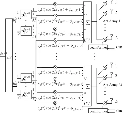
Fig. 1: Downlink transmitter schematic diagram for the MC DS-CDMA employingM transmit antennas, each of which hasLarray elements, when BS transmitter preprocessing is employed.
We assume that the MC DS-CDMA supports K = KG down-link users, which is divided into G groups and each group con-tains K users. The K users in a given group, say group g, share a common T-domain spreading sequence expressed as cg = [cg[0],· · ·, cg[Ne−1]]T of lengthNe. Furthermore, it is assumed
thatcg is orthogonal tocq, wheng6=q. Let, after the 1-to-U serial-to-parallel (S/P) conversion in Fig. 1, the data bits to be transmitted to thekth downlink user in thegth group be expressed as
b(g,k)=hb(1g,k), b (g,k) 2 , . . . , b
(g,k)
U
iT
(1)
where one bit is transmitted by invoking V subcarriers. Therefore, the total number of subcarriers in the MC DS-CDMA system isU V. Specifically, the subcarriers invoked for transmitting the uth, u = 1, . . . , U, bit of thekth user in thegth group are{fu1, fu2, . . . , fuV}.
As shown in Fig. 1, in the context of the uvth subcarrier, the data bit b(ug,k) is first preprocessed by a M-length vector p(uvg,k),
yielding M outputs corresponding to the M transmit antennas. After the preprocessing the signals are then spread using the T-domain spreading codecg(t) =PNn=0e−1cg[n]PTc(t−nTc), where PTc(t) represents the typical rectangular chip waveform of width Tc, Tc represents the chip-duration and, furthermore, Ne =Ts/Tc
represents the spreading factor, Ts =U Tb is the symbol-duration,
while Tb is the bit-duration. As shown in Fig. 1, following the
T-domain spreading, the signals are carrier modulated and, finally, transmitted by theM antenna arrays, where the array elements may be weighted correspondingly based on certain optimization criterion with the aid of the knowledge about the CIRs of the downlink channels.
Based on the above description, it can be shown that the baseband equivalent signals transmitted to theKusers in thegth group can be
expressed as
s(g)(t) =
r
2P V L
K
X
k=1
U
X
u=1
V
X
v=1
W(g,k)p(uvg,k)b
(g,k)
u
×cg(t) exp (2πfuvt+φ(uvg,k))
g= 1,2, . . . , G (2)
wherePrepresents the transmitted power to each of theKusers,V L is a power normalization factor, whereV is due to theV subcarriers conveying the same data bit, whileLis due to the number of array elements. Furthermore, in (2)W(g,k)is the(M L×M)-dimensional
transmitter beamforming matrix for theM antenna arrays, which can be expressed as
W(g,k)=
2
6 6 6 6 4
w1(g,k) 0 · · · 0
0 w(2g,k) · · · 0
..
. ... . .. ...
0 0 · · · wM(g,k)
3
7 7 7 7 5
(3)
where 0 is a L-length vector with entries of zeros, wm(g,k) is
the transmitter beamforming vector, which can be optimized with various optimization criteria [13]. In this contribution, specifically, we assume a low-complexity matched-filtering (MF) assisted transmitter beamforming scheme. Furthermore, we assume that the distance between two adjacent array elements of a given antenna array is half of the wavelength of the radio-frequency (RF) carrier. In this case, it can be shown that the weight vector wm(g,k) achieving the
MF-assisted transmitter beamforming is given by
w(mg,k)= [1 exp (−j[πsin (ψm(g,k))]) · · ·
exp (−j[(L−1)πsin (ψ(mg,k))])] T
m= 1, . . . , M; g= 1, . . . , G; k= 1, . . . , K (4)
whereψ(mg,k)is the DoA in terms of the signals transmitted from the
mth antenna array to thekth user in thegth group.
B. Receive Model
Let the CIR with respect to theuvth subcarrier from themth BS antenna array to thekth user in thegth group be expressed as
¯
h(uv,mg,k) =h(uv,mg,k) ·[1 exp (j[πsin (ψ(mg,k))]) · · ·
exp (j[(L−1)πsin (ψ(mg,k))])] T
g= 1, . . . , G; k= 1, . . . , K; m= 1, . . . , M;
u= 1, . . . , U; v= 1, . . . , V (5)
where, again, ψm(g,k) is the DoA in the context of the signals
transmitted from themth antenna array to the kth user of thegth group,h(uv,mg,k) is the complex-valued fading gain of theuvth subcarrier
channel connecting themth antenna array with thekth user of the gth group.
It can be shown that we have
¯ h(uv,mg,k)Tw
(g,k)
m =Lh
(g,k)
uv,m. (6)
Therefore, the transmitter beamforming seen in (2) is a MF-based transmitter beamforming scheme, which maximizes the output SNR, when communicating over Gaussian channels without multiuser and inter-channel interference. Let
¯ h(uvg,k)=
h
¯
h(uv,g,k1)T,· · ·,h¯(uv,Mg,k)Ti T
which is a M L-length vector containing the CIRs of theM Larray elements. Then, it can be shown that the inner product between¯h(uvg,k)
and W(g,j) can be expressed as
¯ h(uvg,k)TW
(g,j)
=Lh(uvg,kj)T (8)
whereh(uvg,kj)is aM-length CIR vector given by
h(uvg,kj)= [h
(g,kj)
uv,1 h (g,kj)
uv,2 · · · h (g,kj)
uv,M] T
(9)
whereh(uv,mg,kj)is given by
h(uv,mg,kj)=h
(g,k)
uv,mw
(g,k)H
m w
(g,j)
m /L (10)
which represents the cross-correlation between thekth andjth users’ array vectors, both users are in thegth group.
Without loss of any generality, let us focus our attention on the signal received by the first (k= 1) user in the first (g= 1) group, which we refer to it as the reference user or signal for convenience. Then, the corresponding received signal can be expressed as
ruv(t) =h¯Tuv× G
X
g=1
s(g)(t) +nuv(t), (11)
where the superscript with the reference user is ignored for conve-nience. In (11)¯h(uvg,k) is given by (7),s(g)(t)is given by (2), while
nuv(t) is a complex AWGN noise, which has a mean zero and a
variance ofσn2 per dimension.
Simple Detection
FFT Simple
Detection based
multi− carrier demo− dulation r(g,k)
RTS
0
RTS
0
cg(t)
cg(t)
y11(g,k)
y12(g,k)
cg(t)
RTS
0
RTS
0
cg(t)
y1(g,kV )
1V
12
U V
ˆ
b(Ug,k) z(Ug,k) yU V(g,k)
11
ˆ
b(1g,k) z(1g,k)
[image:3.612.73.288.340.482.2]P
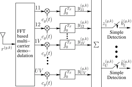
Fig. 2: Receiver schematic block diagram for thekth downlink user in thegth group.
The receiver structure for thekth downlink user in thegth group is shown in Fig. 2. As shown in Fig. 2, after the multicarrier demodulation with the aid of the fast Fourier transform (FFT), the output signals are processed by a bank ofU V MFs associated with the spreading code cg(t), which provide U V observations. Finally,
for each of theUbits, sayb(ug,k), theV observations corresponding to
theV subcarriers conveyingb(ug,k) is combined, in order to generate
the decision variablezu(g,k) forb(ug,k).
According the above discussion and remembering that the G T-domain spreading codes and the different subcarrier signals are orthogonal, it can be shown that the MF’s output corresponding to the uvth subcarrier of the reference user can be expressed as
yuv=
r
2P V L
K
X
k=1
¯
hTuvW(g,k)p(uvg,k)b
(g,k)
u +nuv
=
r
2P L V
K
X
k=1
h(uvg,k)Tp
(g,k)
uv b
(g,k)
u +nuv (12)
where the elements inh(uvg,k) are given by (10), while the Gaussian
noise samplenuv is given by
nuv= 1
Ts
ZTs
0
nuv(t)cg(t) exp (−j2πfuvt)dt (13)
which has mean zero and a variance ofσ2
n/Ts per dimension.
Finally, the decision variable forb(ug,1)can be obtained as
zu= V
X
v=1
yuv, (14)
andb(ug,1)is decided according to
ˆb(g,1)
u =sgn(<(zu)), u= 1,2, . . . , U (15)
where<(z)represents the real part ofz.
According to the detection scheme as above-described, the detec-tor consists of a bank of MFs and hence has an extremely low-complexity. Furthermore, as seen in (12), the detection is free-from multicarrier interference. There is also no interference from the users in the other groups. However, when the array vectors of the users in the same group are not orthogonal, these users may interfere with each other, yielding the intra-group MUI. In the next section we will show that the intra-group MUI can be fully removed with the aid of the SVD-assisted transmitter preprocessing.
III. TRANSMITTERPREPROCESSINGBASED ONSINGULAR
VALUEDECOMPOSITION
In this section we consider the design of the transmitter prepro-cessing vector p(uvg,k) seen in (12), so as to achieve simultaneously
two objectives: to remove fully the intra-group MUI and to guarantee a transmit diversity order ofnt in S-domain. Our design starts with
expressing the preprocessing vectorp(uvg,k) as
puv(g,k)=Puv(g,k)d(uvg,k) (16)
whereP(uvg,k) is(M×nt), which is designed to suppress the
intra-group MUI, whiled(uvg,k) is ant-length vector used to combine the
resultant signals in the S-domain, in order to achieve a diversity order ofnt in the S-domain. Let us first consider the design ofP(uvg,k).
A. Design ofP(uvg,k): Intra-Group MUI suppression
As shown in (12), the intra-group MUI can be fully removed, if the component preprocessing matrices
n
P(uvg,j)
o
are chosen to satisfy
h(uvg,k)TP
(g,j)
uv =0
T
nt, fork6=j (17)
where0nt is ant-length all-zero vector. Therefore, according to [7],
the component preprocessing matrixP(uvg,j) for user jshould lie in
the null subspace determined by
H(uvg,j)T=
h
h(uvg,1),· · ·,h
(g,j−1)
uv ,h
(g,j+1)
uv ,· · ·,h
(g,K)
uv
iT
,
j= 1,2, . . . , K (18)
which is composed by the spatial signatures of the users except user j.
Upon carrying out the SVD onH(uvg,j) [13], we can express it as
H(uvg,j)=U
(g,j)
s,uv
h
D(uvg,j) 0
i "
V(s,uvg,j)H V(n,uvg,j)H
#
, (19)
Vs,uv(g,j) is a(M×(K−1))orthonormal matrix corresponding to the
signal subspace determined by the (K−1)interfering users, while
Vn,uv(g,j) is a(M×(M−K+ 1))orthonormal matrix corresponding
to the orthogonal subspace ofH(uvg,j).
Let nt = M−K+ 1. It can be shown that nt represents the
transmit diversity order achieved by the MC DS-CDMA system in the S-domain. Hence, nt is referred to as the number of effective
transmit antennas. In this case, the component preprocessing matrix
P(uvg,j) can be chosen as
Puv(g,j)=Vn,uv(g,j), j= 1,2, . . . , K (20)
Let us now consider the design of the component preprocessing matrixd(uvg,k)in (16).
B. Design ofd(uvg,k): Transmit Diversity Combining
Upon applying the preprocessing matricesnp(uvg,j)
o
of (16)
asso-ciated with the component preprocessing matricesnP(uvg,j)
o of (20) into (12), it can be shown that the intra-group MUI imposed on user 1 is fully removed. Furthermore, the reference user’s signal is projected onto ant-dimensional orthogonal subspace. Let
e(uvg,1)=P
(g,1)T
uv h
(g,1)
uv (21)
wheree(uvg,1)can be expressed as
e(uvg,1)=
h
e(uv,g,1)1 · · · e(uv,ng,1)t iT
(22)
Consequently, we can express the component preprocessing matrix
d(uvg,1)as
d(uvg,1)=
h d(uv,g,1)1, d
(g,1)
uv,2, . . . , d (g,1)
uv,nt iT
(23)
and letd(uv,ig,1) equal to
d(uv,ig,1)=e(uv,ig,1)∗/ q
E(uvg,1) (24)
wheree(uv,ig,1)∗is the conjugate ofe(uv,ig,1) and
Euv(g,1)= nt X
i=1
˛ ˛ ˛e
(g,1)
uv,i
˛ ˛ ˛
2
(25)
is for achieving the constraint on the transmitted power, so that the total transmitted power to a remote user maintains unchanged before and after the preprocessing.
Finally, upon substituting (16) associated with the component preprocessing matricesnP(uvg,j)
o
of (20) andd(uvg,1)of (23) into (12),
it can be shown that the decision variable for b(ug,1), u= 1, . . . , U
of the reference user can be expressed as
yuv=
r
2P L V
q
Euv(g,k)b(uvg,k)+nuv,
u= 1, . . . , U; v= 1, . . . , V (26)
which is free from inter-group interference, multicarrier interference and intra-group MUI.
C. Discussion
It is well-known that, in a conventional single-carrier DS-CDMA system [3] using Ne-chip Walsh-Hadamard (WH) codes as the
T-domain spreading sequences, the maximum number of users support-able is K =Ne without BER degradation in comparison with the
corresponding single-user DS-CDMA system. By contrast, the MC
DS-CDMA system considered in this contribution has the following characteristics.
• The diversity order achieved isV nt=V(M−K+ 1), where
V is in the F-domain, whilent is in the S-domain;
• The number of users supportable is K=NeK, 1≤K≤M,
where Ne is the length of the T-domain spreading sequences,
whileKis the number of users per group. With the aid of the transmitter preprocessing proposed in Sections III-A and III-B, the K= NeK number of users can be supported by the MC
DS-CDMA system without significant performance degradation in comparison with the single-user MC DS-CDMA system;
• There exists a trade-off between the number of users supported and the diversity order achieved. In the extreme case when the diversity order is V corresponding tont =M−K+ 1 = 1,
which impliesK=M, the number of users supportable is as high asK=NeM. If the MC DS-CDMA system supports only K=Ne users implying that each group has onlyK= 1user,
then the corresponding diversity order achieved isV nt=V M.
Let us now show our simulation results in the next section.
IV. SIMULATIONRESULT
In this section the BER performance of the MC DS-CDMA system using multiple BS transmit antenna arrays is investigated, when assuming that each subcarrier signal experiences flat Rayleigh fading. In our simulations we assumed that the F-domain diversity isV = 4
and that the T-domain spreading sequences were theNe= 32-length
WH codes. The BER performance of the MC DS-CDMA using the proposed transmitter preprocessing is also compared with that of the other MC DS-CDMA systems investigated in the literature as detailed in our forthcoming discourse.
The details about the legends in Figs. 3 and 4 are as follows. For the MC DS-CDMA using the SVD-assisted transmitter preprocessing, the corresponding curves are indicated by ‘(M(nt)×L) TP-SVD’,
whereM is the number of transmit antenna arrays,Lis the number of array elements of each antenna array andntrepresents the number
of effective (logical) transmit antennas. In Figs. 3 and 4 the legend ‘(1,1)’ indicates the MC DS-CDMA system using no preprocessing, ‘(1, L)BF’ corresponds to the MC DS-CDMA system using only the steered beamforming, while ‘(M, L) SSTS’ corresponds to the MC DS-CDMA system using both the steered beamforming and space-time spreading (STS).
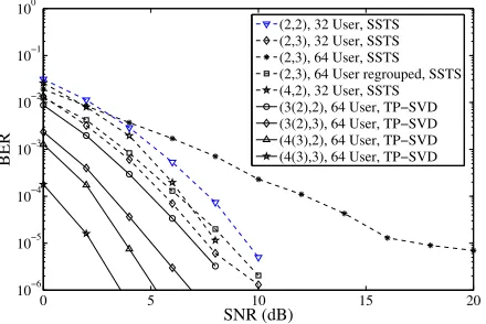
From the results in Figs. 3 and 4, it can be seen that, when assuming orthogonal multicarrier signals and that the subcarrier signals experience flat-fading, a conventional MC DS-CDMA using Ne-length T-domain spreading sequences is capable of supporting at
mostK=Ne users without significant BER degradation compared
to that of the single-user system. In [5] the MC DS-CDMA system is assumed to employ both T-domain and F-domain, i.e, TF-domain, spreading, in order to extend the maximum number of users sup-portable by the system. However, as shown in Figs. 3 and 4, when the MC DS-CDMA system using TF-domain spreading supports
K = 2Ne = 64 users instead of K = Ne = 32 users, the BER
performance is significantly degraded. By contrast, when the SVD-assisted transmitter preprocessing is employed, as shown in Figs. 3 and 4, the MC DS-CDMA systems supporting K = Ne = 32, K= 2Ne= 64andK= 3Ne = 96users are capable of achieving
a similar BER performance.
0 5 10 15 20 10−6
10−5 10−4
10−3
10−2 10−1 100
SNR (dB)
BER
[image:5.612.65.281.62.214.2](1,1), 1 User (1,2), 1 User, BF (1,4), 1 User, BF (1,4), 32 User, BF (2,2), 32 User, SSTS (2,2), 64 User, SSTS (2,2), 64 User regrouped, SSTS (2(2),2), 32 User, TP−SVD (3(2),2), 64 Users, TP−SVD (4(2),2), 96 Users, TP−SVD
Fig. 3: BER versus SNR performance of the downlink MC DS-CDMA system using V = 4 subcarriers and Ne = 32-chip WH
codes based T-domain spreading.
0 5 10 15 20
10−6
10−5
10−4 10−3 10−2 10−1 100
SNR (dB)
BER
(2,2), 32 User, SSTS (2,3), 32 User, SSTS (2,3), 64 User, SSTS (2,3), 64 User regrouped, SSTS (4,2), 32 User, SSTS (3(2),2), 64 User, TP−SVD (3(2),3), 64 User, TP−SVD (4(3),2), 64 User, TP−SVD (4(3),3), 64 User, TP−SVD
Fig. 4: BER versus SNR performance of the downlink MC DS-CDMA systems using V = 4 subcarriers and Ne = 32-chip WH
codes based T-domain spreading.
single transmit antenna array (M = 1) with single array element (L = 1), the BER performance is the worst. Secondly, when the MC DS-CDMA system employs M = 1 BS antenna array with L > 1array elements, the received SNR is significantly improved and the corresponding curves are shifted to the left-hand side of that corresponding to the case of L = 1. Thirdly, when the MC DS-CDMA system employs M > 1 BS antenna arrays and each antenna array has L > 1 array elements, and when the steered transmitter beamforming and STS (SSTS) are applied, the MC DS-CDMA system is capable of achieving a transmit diversity order of M, in addition to the SNR enhancement due to the antenna arrays [5]. Furthermore, as can be seen in Figs. 3 and 4, when the MC DS-CDMA BS transmitter employs our SVD-assisted transmitter preprocessing indicated by ‘TP-SVD’, the BER performance is further improved, in comparison with the system using SSTS. In comparison with the SSTS scheme, which does not depend on the knowledge about the downlink CIRs, except the DoAs for the steered beamforming, the SVD-assisted transmitter preprocessing requires the knowledge about the downlink CIRs. However, the SSTS-assisted transmitting scheme demands a relatively higher complexity detection
scheme, such as multiuser detection (MUD), than the SVD-assisted transmitter preprocessing, which requires only the low-complexity MF-assisted detection.
V. CONCLUSION
In this contribution we have proposed and investigated a SVD-assisted transmitter preprocessing scheme for the MC DS-CDMA system using multiple BS transmit antenna arrays, where each antenna array employs multiple array elements. The SVD-assisted transmitter preprocessing has been designed, in order to support possibly a high number of downlink users, while simultaneously to achieve the highest possible transmit diversity gain. Our study shows that, for a SVD-assisted MC DS-CDMA system usingM transmit antenna arrays and length-Ne T-domain spreading sequences, the
number of users supportable can be as high as M Ne with the aid
of both the T-domain and S-domain multiuser multiplexing. Our simulation results show that the SVD-assisted MC DS-CDMA system is capable of supporting such a high number of users with near single-user BER performance achieved by a corresponding MC DS-CDMA system supporting only one downlink user.
REFERENCES
[1] L. L. Yang and L. Hanzo, “Multicarrier DS-CDMA: A multiple-access scheme for ubiquitous broadband wireless communications,”IEEE Com-munications Magazine, vol. 41, no. 10, pp. 116–124, October 2003. [2] L.-L. Yang and L. Hanzo, “Performance of generalized multicarrier
DS-CDMA over Nakagami-mfading channels,”IEEE Transactions on Communications, vol. 50, pp. 956 – 966, June 2002.
[3] L.Hanzo, L.-L. Yang, E.-L. Kuan, and K.Yen,Single- and Multi-Carrier DS-CDMA Multi-User Detection, Space-Time Spreading, Synchronisa-tion and Standards. Chichester, UK: John Wiley and Sons, Ltd, 2003. [4] B. Hu, L.-L. Yang, and L. Hanzo, “Performance of the smart antenna aided multicarrier DS-CDMA uplink,” inIEEE 60th Vehicular Technol-ogy Conference. IEEE, September 2004, pp. 191 – 195.
[5] B. Hu, L.-L. Yang, and L.Hanzo, “Performance of the smart antenna aided generalized multicarrier DS-CDMA downlink using both time-domain spreading and steered space-time spreading,”IEEE 62nd Ve-hicular Technology Conference,, vol. 1, no. 28-25, pp. 458–462, Sept. 2005.
[6] S. Verdu,Multiuser Detection. Cambridge University Press, 1998. [7] L.-U. Choi and R. Murch, “A transmit preprocessing technique for
multiuser MIMO systems using a decomposition approach,”IEEE Trans-actions on Wireless Communications, vol. 3, no. 1, pp. 20 – 24, 2004. [8] R. L.-U. Choi and R. D. Murch, “New transmit schemes and simplified
receivers for MIMO wireless communication systems,”IEEE Trans-actions on Wireless Communications, vol. 2, no. 6, pp. 1217–1230, November 2003.
[9] R. L.-U. Choi, M.T.Ivrlac, R. D. Murch, and W. Utschick, “On strategies of multiuser MIMO transmit signal processing,”IEEE Transactions on Wireless Communications, vol. 3, no. 6, pp. 1936–1941, November 2004. [10] R. L.-U. Choi and R. D. Murch, “A pre-BLAST-DFE technique for the downlink of frequency-selective fading MIMO channels,” IEEE Transactions on Communications, vol. 52, no. 5, pp. 737–743, May 2004.
[11] ——, “A transmit MIMO scheme with frequency domain pre-equalization for wireless frequency selective channels,”IEEE Transac-tions on CommunicaTransac-tions, vol. 3, no. 3, pp. 929–938, May 2004. [12] ——, “Transmit-preprocessing techniques with simplified receivers for
the downlink of MISO TDD-CDMA systems,”IEEE Transactions on Vehicular Technology, vol. 53, no. 2, pp. 285–295, March 2004. [13] S. Haykin,Adaptive Filter Theory, 3rd ed. Upper Saddle River, New
[image:5.612.62.282.281.428.2]