City, University of London Institutional Repository
Citation
:
Slingsby, A. (2003). An Object-Orientated Approach to Hydrological Modelling using Triangular Irregular Networks. Paper presented at the GISRUK03, Apr 2003, London, UK.This is the unspecified version of the paper.
This version of the publication may differ from the final published
version.
Permanent repository link:
http://openaccess.city.ac.uk/568/Link to published version
:
Copyright and reuse:
City Research Online aims to make research
outputs of City, University of London available to a wider audience.
Copyright and Moral Rights remain with the author(s) and/or copyright
holders. URLs from City Research Online may be freely distributed and
linked to.
City Research Online: http://openaccess.city.ac.uk/ [email protected]
An Object-Orientated Approach to Hydrological Modelling using Triangular Irregular Networks
Aidan Slingsby
Centre for Advanced Spatial Analysis University College London 1-19 Torrington Place, Gower Street
London, WC1E 6BT UK
Introduction
This paper describes an approach to hydrological modelling with two characteristics: a) the terrain is modelled with a triangular irregular network (TIN) instead of more commonly used
rasters; and b) an object orientated approach is used, which allows data and process to be embedded in the same data structure.
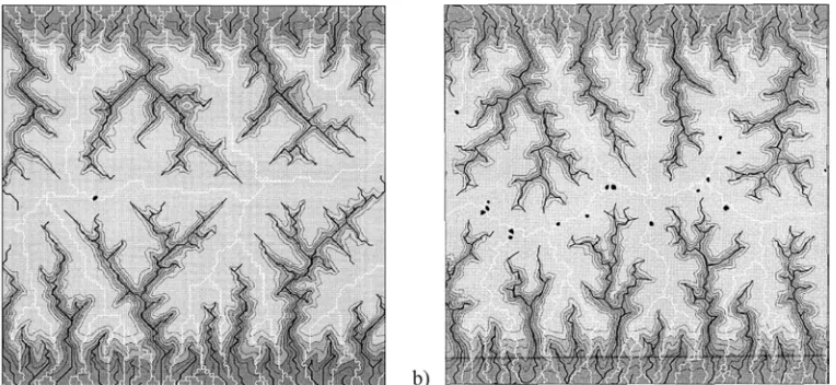
[image:2.612.126.508.484.660.2]Comparisons of TINs and rasters for terrain modelling are well reported in the literature. Data models for environmental modelling are most commonly based on rasters, but some researchers (e.g. Braun and Sambridge, 1997; Tucker et al., 2001) have observed that under certain circumstances, artefacts of the underlying regularity of rasters may manifest themselves in the model output (see Figure 1). This is partly due to the simple method by which flow direction is most commonly approximated in rasters; flow from each cell is routed into the lowest one of its nearest eight neighbours (the ‘D8’ method, O’Callaghan and Mark, 1984). Other, more sophisticated methods do exist. Deterministic methods include Quinn’s (1991) multiple-flow routing algorithm and Lea’s (1992) routing according to a local aspect best-fit plane; a disadvantage of the former, is that flow tends to diverge. Methods with a stochastic element include ‘Rho8’ by Fairfield and Leymarie (1991); a disadvantage of these methods is that different results are obtained with the same input parameters over multiple model runs. A good review of these methods is by Gallant and Wilson (2000). Flowpaths over a TIN surface can be computed using the steepest lines of descent of TIN facets (Jones et al., 1990) in any orientation, rather than being based on 45º direction increments.
The object-orientated approach models the terrain as a set of interacting TIN elements (nodes, edges and facets). The approach of dealing with 0D, 1D and 2D elements of space in a 2D data model is common. For hydrological modelling purposes, this also allows channel flow (along concave edges) and overland flow (over facet areas) to be modelled separately. Each TIN element is an ‘object’ which holds data (properties) about itself, and also has the ability (through methods) to build itself, derive spatial relationships with its surrounding TIN elements, and model hydrology upon itself. The set of interacting objects, each responsible for its local operations, forms an ‘intelligent landscape’ model, into which both data and process are embedded. The delegation of methods in this localised way greatly simplifies the implementation of the model, in which operations are completed using a piecemeal approach.
TINMOD (Slingsby, 2002) is a prototype implementation of a TIN-based ‘intelligent landscape’ for hydrological modelling. Its design is described and discussed in the context of hydrological modelling.
The Data Model
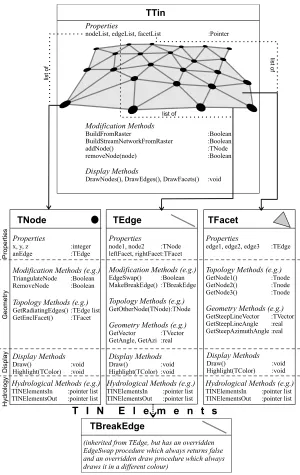
Figure 2 illustrates the data model. The TIN is composed of three types of TIN elements, modelled by the classes TNode, TEdge and TFacet. These are organised by an instance of the class TTin, which has methods for its building and maintenance and has three lists of pointers to its three types of TIN element, held as properties (state variables). Strictly speaking, only one pointer to one individual TIN element is required, since the TIN can easily be traversed by virtue of the TIN elements’ storage and capabilities for deriving its topologies.
Creation and Derivation of Topology
The TNode class stores its position as three integer properties. A pointer to any one of the edges attached to it is also stored. This is the starting point of the GetRadiatingEdges method which returns a list of pointers to all the edges which are attached to it by using the adjacency information of the edges, and working around the node until the starting edge is reached. When nodes are added to the TIN, new edges and facets are automatically created and added. The triangulation is updated to meet the Delaunay triangulation criterion (this is commonly used for modelling terrains as it maximises the angles, producing ‘fat’ triangles, improving height interpolation between nodes). A triangulation can be made to conform to the Delaunay criterion by ‘swapping’ certain edges to their alternative configuration as described by Sloan (1987).
The TEdge class stores pointers to the nodes that define its two end points and to the facets that lie on its left and right (with respect to node1). The TBreakEdge class is inherited from this and instances of it can be treated in exactly the same way as instances of TEdge – the difference is in its behaviour when the EdgeSwap method is called. Instances of the TBreakEdge class will not let their configuration be changed. This is an example of the object-orientated concept of
polymorphism.
The TFacet class stores pointers to the three edges which define it. Its methods GetNode1,
GetNode2 and GetNode3 are used to return its three nodes.
Display
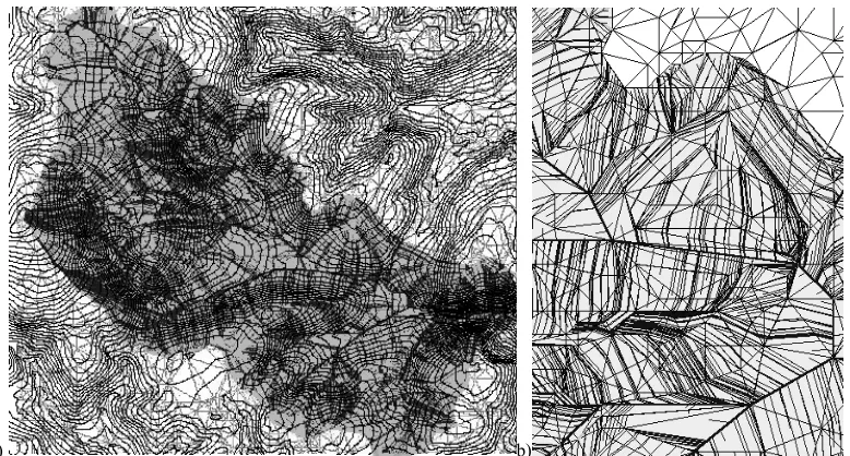
All the TIN elements have a Draw method for drawing themselves on-screen. TTin has methods for drawing all instances of each TIN element in its pointer lists. The Highlight method allows a display colour to be specified. These methods produced the outputs seen in Figure 5.
Properties
Modification Methods (e.g.)
Topology Methods (e.g.)
x, y, z :integer anEdge :TEdge
TriangulateNode :Boolean RemoveNode :Boolean
GetRadiatingEdges() :TEdge list GetEnclFacet() :TFacet
TNode
Hydrological Methods (e.g.)
TINElementsIn :pointer list TINElementsOut :pointer list
TBreakEdge
Hydrological Methods (e.g.)
TINElementsIn :pointer list TINElementsOut :pointer list
TEdge
Properties
Modification Methods (e.g.)
Topology Methods (e.g.)
Geometry Methods (e.g.)
Display Methods
node1, node2 :TNode leftFacet, rightFacet:TFacet EdgeSwap() :Boolean MakeBreakEdge() :TBreakEdge GetOtherNode(TNode):TNode GetVector :TVector GetAngle, GetAzi :real Draw() :void Highlight(TColor) :void
Hydrological Methods (e.g.)
TINElementsIn :pointer list TINElementsOut :pointer list
TFacet
Properties
Topology Methods (e.g.)
Geometry Methods (e.g.)
edge1, edge2, edge3 :TEdge
GetNode1() :Tnode GetNode2() :Tnode GetNode3() :Tnode GetSteepLineVector :TVector GetSteepLineAngle :real GetSteepAzimuthAngle :real TTin Properties
nodeList, edgeList, facetList :Pointer
Modification Methods Display Methods BuildFromRaster :Boolean BuildStreamNetworkFromRaster :Boolean addNode() :TNode removeNode(node) :Boolean DrawNodes(), DrawEdges(), DrawFacets() :void
(inherited from TEdge, but has an overridden EdgeSwap procedure which always returns false and an overridden draw procedure which always draws it in a different colour)
T I N E l e m e n t s
[image:4.612.160.460.69.544.2]P rope rt ie s Ge ome tr y Di sp la y Hyd rol ogy list o f lis t o f list of Display Methods Draw() :void Highlight(TColor) :void Display Methods Draw() :void Highlight(TColor) :void
The Representation of Terrain
A TIN is created from an irregular sample of point data. One method of generating this is to run an algorithm on a raster landscape model to generate the set of nodes required to build a TIN terrain model whose surface does not deviate outside a user-defined threshold from the original (raster) terrain model. The Hierarchy Method (de Floriani et al 1984, cit Lee, 1991) performed well (Slingsby, 2002). This iterative technique builds a TIN node-by-node by a) comparing the intermediate TIN as it is built, with the original (raster) terrain representation, b) generating the node which would make the intermediate TIN most like the original terrain, c) adding this to the TIN, d) repeating until the TIN represents the original terrain within a user-defined tolerance. Since the adding of each node invokes all the necessary triangulation and topology-building methods, the triangulation is always up to date. This adaptive nature ensures that the TIN can be compared at each iteration.
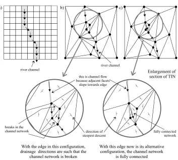
Delaunay triangulation produces the most satisfactory triangulation for modelling surfaces. However, if certain linear features need to be represented in a TIN, the TIN must be constrained to ensure that edges are coincident with linear features, whether or not they meet the Delaunay triangulation criterion. Since TINMOD defines channels as concave edges (whose two adjacent facets slope towards the edge), it is essential that the river channel networks are fully represented and fully connected. Figure 3 shows how a pure Delaunay triangulation may result in a broken
a) b) c)
Enlargement of section of TIN
With the edge in this configuration, drainage directions are such that the
channel network is broken
With this edge now is its alternative configuration, the channel network
is fully connected this is channel flow
because adjacent facets slope towards edge
direction of steepest descent river channel
river channel
breaks in the
channel network fully connected
[image:5.612.135.488.57.374.2]network
channel network. Tucker et al (2001) considered that modelling channel in this way was not robust enough (since it is too much dependent on the edge configuration of the TIN). Instead, all flow is modelled as one flow-type, routing all flow over Voronoi polygons, rather modelling flow over facets (overland flow) and along edges (channel flow) separately. The Voronoi method can be used for long term geomorphological models. It is less suited to hydrological modelling, because channel flow (governed by different physics than overland flow) is not modelled. TINMOD creates a suitable constrained TIN by extracting channel- and ridge-line data from the original raster, and adding them as a series of breaklines, before the rest of the TIN is built with the Hierarchy Method.
In the future, it also may be possible to constrain TINs with additional information such as land parcel data, where parcels may have different hydrological properties based on the land use.
Hydrological Methods
Each TIN element can ascertain its geometry (with methods such as TFacet’s
GetSteepestLineVector method) and which TIN elements are both upslope and downslope from it. Thus an edge ‘knows’ that if it is a ‘channel’, flow will leave the edge through its lowest node and that flow may enter it from its highest node and from the facets on either side as overland flow. If the edge is not a ‘channel’, flow may also leave by the adjacent facets which slope away from it. A facet ‘knows’ that flow will always move along its path of steepest descent/ascent. From this, it also ‘knows’ through which edge(s) or node(s) flow will leave or
b)
a) c) d)
e) f) g)
h) i) j)
110
30 50 70 90
FacetA
Edge B
Edg eC
E dg eD
NodeA
NodeB
NodeC
Initiate flow at position(x,y)
position (x y )2 2
position (x y )11
Flowline 120
FacetB
EdgeA
a: Delineating flowlines b-j: Delineating basins
channel segment
[image:6.612.113.515.66.302.2]channel segment
Figure 4: The piecemeal approach. (a) Delineating flowlines. Flow is initiated at the position x,y. FacetA can ascertain that the exit TIN element is EdgeA at position x1,y1. EdgeA can ascertain that is it
enter. Edges can then derive at which point upon them flow entered or left, by the angle of the input or output facet. Nodes can likewise do this; within a channel network they may be the points at which flow diverges upstream or downstream. Flowpaths can thus be defined as a whole using this piecemeal approach. See Figure 4a.
Basins can be delineated by finding all the edges and areas of facet which flow into the basin output (a single node), and then repeating this for all the edges and areas of facet which flow into these. Since facets have either one input edge and two outputs edges, or two input edges and one output edge, and since input edges may contribute to more than one output edge, dynamic segmentation of edges is used to identify sub-areas of facets. See Figure 4b-j.
Conclusion
This paper has briefly outlined an object-orientated TIN approach to hydrological modelling. The use of the TIN aims to free the model of some of the common constraints imposed by rasters. The model relies on the existence of a fully connected channel network, and does this by constraining the TIN, based on channel information extracted from the original raster. Two types of flow are modelled, overland flow (on facets) and channel flow (along concave edges). For basin delineation, facets can be dealt with at a sub-facet level.
The object-oriented approach models the system as a set of interacting objects, each with relatively simple behaviours. This approach simplifies the data structure by allocating tasks (methods) to localised structural elements of the TIN (nodes, edges and facets), invoking these methods to reflect dynamic change and providing a unified modelling framework in which the terrain and hydrological processes can be modelled in a piecemeal fashion.
[image:7.612.121.510.92.301.2]a) b)
Figure 5 shows some output examples from TINMOD. The implementation and some initial tests (although the latter are not discussed here) of the prototype TINMOD, have shown that this approach is both technically feasible and valid (Slingsby, 2002).
References
Braun, J. and Sambridge, M. 1997. Modelling Landscape Evolution on Geological Time Scales: a New Method Based on Irregular Spatial Discretization. Basin Research 9, pp27–52.
Fairfield, J., Leymarie, P. 1991 Drainage networks from grid digital elevation models. Water Resources Research 27, pp709–717.
Gallant, J.C. and Wilson, J.P. 2000 Primary Topographic Attributes. In Gallant and Wilson (eds.), Terrain Analysis, Principles and Applications. J. Wiley & Sons, pp51–86.
Jones, N.L., Wright, S.G., Maidment, D.R., 1990. Watershed delineation with triangle-based terrain models. Journal of Hydraulic Engineering 16 (10), pp 1232– 1251.
Lea, N.J. 1992. An aspect-driven kinematic routing algorithm. In Parson and Abrahams (eds.), OverLand Flow: Hydraulics and Erosion Mechanics. London, UCL Press.
Lee, J. 1991. Comparison of existing methods for building triangular irregular network models of terrain from grid digital elevation models. International Journal of Geographical Information Systems 5, pp267–285.
O’Callaghan, J.F. and Mark, D.M. 1984 The Extraction of Drainage Networks from Digital Elevation Data Computer Vision, Graphics and Image Processing 28, pp323–344.
Quinn, P.F, Beven, K.J., Chevallier, P., Planchon, O. 1991. The Prediction of Hillslope Flow Paths for Distributed Hydrological Modelling using Digital Terrain Models. Hydrological Processes 5, pp59–79.
Slingsby, A.D., 2002. An object-orientated approach to hydrological modelling based on a triangular irregular network. MSc thesis (unpublished), Department of Geography, University of Edinburgh.
Sloan, S.W. 1987. A fast algorithm for constructing Delaunay triangulations in the plane. Advances in Engineering Software 9 (1), pp34-55.
Tucker, G., Gasparini, N., Bras, R., Rybarczyk, S. 2001. An object-orientated framework for distributed hydrologic and geomorphic modeling using triangulated irregular networks. Computers and Geosciences 27 (8), pp959–973.