Sims, O.N. and Irvine, J. (2007) An FPGA implementation of
pattern-Selective pyramidal image fusion. In: 16th International Conference on
Field Programmable Logic and Applications, 2006-08-28 - 2006-08-30,
Madrid. , http://dx.doi.org/10.1109/FPL.2006.311296
This version is available at
https://strathprints.strath.ac.uk/37150/
Strathprints is designed to allow users to access the research output of the University of Strathclyde. Unless otherwise explicitly stated on the manuscript, Copyright © and Moral Rights for the papers on this site are retained by the individual authors and/or other copyright owners. Please check the manuscript for details of any other licences that may have been applied. You may not engage in further distribution of the material for any profitmaking activities or any commercial gain. You may freely distribute both the url (https://strathprints.strath.ac.uk/) and the content of this paper for research or private study, educational, or not-for-profit purposes without prior permission or charge.
Any correspondence concerning this service should be sent to the Strathprints administrator:
The Strathprints institutional repository (https://strathprints.strath.ac.uk) is a digital archive of University of Strathclyde research outputs. It has been developed to disseminate open access research outputs, expose data about those outputs, and enable the
AN FPGA IMPLEMENTATION OF PATTERN-SELECTIVE PYRAMIDAL IMAGE FUSION
Oliver Sims
∗Institute for System Level Integration
Alba Campus
Livingston, Scotland, UK
[email protected]
James Irvine
Department of Electrical & Electronic
Engineering
University of Strathclyde
Glasgow, Scotland, UK
ABSTRACT
The aim of image fusion is to combine multiple images (from one or more sensors) into a single composite im-age that retains all useful data without introducing artefacts. Pattern-selective techniques attempt to identify and extract whole features in the source images to use in the compos-ite. These techniques usually rely on multiresolution image representations such as Gaussian pyramids, which are lo-calised in both the spatial and spatial-frequency domains, since they enable identification of features at many scales simultaneously. This paper presents an FPGA implementa-tion of pyramidal decomposiimplementa-tion and subsequent fusion of dual video streams. This is the first reported instance of a hardware implementation of pattern-selective pyramidal im-age fusion. Use of FPGA technology has enabled a design that can fuse dual video streams (greyscale VGA, 30fps) in real-time, and provides approximately 100 times speedup over a 2.8GHz Pentium-4.
1. INTRODUCTION
Image fusion allows multiple observations of a scene to be combined, in order to increase the information content pre-sented in a single image, and make the image more effective for its intended application. The images to be fused may originate from a single sensor, perhaps taken with different points of focus, or from multiple sensors that are sensitive to different spectral regions. Image fusion has been used widely in medical, manufacturing, military, and security ap-plications, amongst others [1]. One modern example where image fusion techniques are proving useful is in the detec-tion of concealed weapons by using a composite of ther-mal and visible-range observations [2]. There are several methods of performing image fusion, with a successful im-plementation being one that retains all useful information from the source images into a single composite image, with-out introducing artefacts. Basic methods take no account of
∗Sponsored by Thales Optronics and EPSRC under the Engineering Doctorate (EngD) programme
the image content and perform simple merging of the image data, for instance averaging. More sophisticated methods work at a higher level by identifying detail in the source im-ages and using a selection process to determine the elements that will be used in the final composite.
Several key methods in image fusion rely on the multi-scale image pyramid [3]. Image pyramids are a decompo-sition of a single image into a series of images of varying resolutions, with each image containing data representative of detail at a particular scale. The advantages of a multi-scale representation lie in its localisation in both spatial and spatial-frequency domains. The fusion algorithm presented here uses pyramids that have been further decomposed into orientation specific pyramids [4], [5], [6]. It uses simple edge filters (gradient filters) to identify details in the source images along four orientations. These edges are compared, and the most useful features are selected according to some measure of saliency and then carried forward into the com-posite image. Using gradient pyramids has been found to reduce the artefacts that other pyramidal methods can in-troduce [4]. The pattern-selective fusion algorithm is com-plicated and requires thousands of calculations to be per-formed in order to produce a single output image. For this reason a microprocessor implementation is inherently slow, and real-time processing unfeasible. However, like many image processing algorithms, there are opportunities to ex-ploit parallelism in the algorithm’s operation that make an FPGA implementation an attractive option.
This paper describes an implementation of a pattern-selective fusion algorithm on a single Virtex-2 FPGA. The design uses several novel approaches to enable dual grey-scale VGA video streams to be fused in real-time. Note that the source images are assumed to be pre-aligned, and auto-matic registration tecniques have not been considered here.
2. PYRAMID GENERATION
The Gaussian or low pass pyramid and Laplacian bandpass pyramids were introduced by Burt in 1983 [7]. These meth-ods have since been used in a wide variety of applications
besides fusion, and were a precursor to the development of more general multiresolution methods, in particular the study of wavelets.
The image to be decomposed forms the bottom level of a notional pyramid. Each subsequent higher level of the pyra-mid is formed by low-pass filtering, and then subsampling by a factor of two, the pyramid level beneath it. The act of low-pass filtering reduces the band limit by one octave, and hence, according to the sampling theorem, subsampling can take place without any loss of information. In reality the generating filter is not ”ideal”, which means that the fol-lowing subsampling may result in aliasing; however these effects are usually disregarded for these purposes [8]. The low-pass filter is usually chosen to be a 5x5 Gaussian, which has the added advantage of being separable.
Hence, each level of the pyramid is produced as
[t]Gk= 2
m=−2 2
n=−2
w(m, n)Gk−1(2i+m,2j+n) (1)
for k=1,...,N;G0≡I, the original image; w is the filter
ker-nel. This process is usually referred to asREDUCE, when
considering the 2D image as a whole:
Gk =REDU CE(Gk−1) (2)
Since each image is half the size in each dimension of the image below it, it consists of one quarter the number of pix-els.
The alternative pyramid type is known as the Laplacian. This is formed as a bandpass pyramid rather than a low pass, and is obtained by subtracting a level of the Gaussian pyra-mid from the level directly beneath it. Each level of the Laplacian pyramid can thus be thought of as a difference image between two corresponding levels of the Gaussian pyramid. Because two levels of the Gaussian pyramid are different sizes, in order to subtract one from another the res-olution of the image at level k+1 must first be increased to the resolution of the image at level k. In order to do this
we use theEXPANDoperation, which involves upsampling
of the smaller image (by inserting zeros), and then interpo-lation of the missing values by a further application of the generating filter kernel. Then:
Lk=Gk−EXP AN D(Gk+1) (3)
There must be one fewer levels in the Laplacian pyramid than in the Gaussian. Typically the Gaussian and Laplacian pyramids are generated with three levels above the base im-age. At levels higher than this the resulting images may be-come too small to be useful, and the edge effects of succes-sive convolutions with the generating kernel become detri-mental. It is possible to perform fusion with less than four pyramid levels, but the ability of the algorithm to distinguish features of different sizes is compromised.
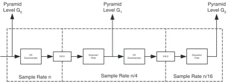
2D
Downsample FIFO Gaussian Filter
2D
Downsample FIFO Gaussian Filter
Sample Rate n Sample Rate n/4 Sample Rate n/16 Pyramid
Level G0
Pyramid Level G1
Pyramid Level G2
Fig. 1. Block diagram of hardware image pyramid genera-tion.
The Gaussian pyramid is the one used in the process of extracting detail from the source images to be used for fu-sion. The Laplacian pyramid and a variant of it known as the FSD Laplacian [9], are used in the inverse pyramid trans-form to reconstruct the composite image.
2.1. Hardware Implementation
A block diagram of the image pyramid generation system with two pyramid levels above the base is shown in Fig. 1. This is a multirate design that allows multiple pyramid lev-els to be generated concurrently. The downsampling stages work by simply discarding certain data values: horizon-tal downsampling occurs by discarding every other sam-ple; vertical downsampling occurs by discarding every other row. The samples that are not discarded are stored in a FIFO that acts as a buffer between pyramid levels. The next pyra-mid level operates at a clock rate that is one quarter that of the level below it, to match the fact that it is receiving one quarter the number of samples. In this way the higher level can run concurrently with the lower level, without empty-ing the FIFO. This structure is repeated for each level of the pyramid, with each level operating at one quarter the clock speed of the level below it. The ability to generate pyramid levels concurrently counteracts the negative effect on per-formance caused by running portions of the design at slower clock speeds. By using this approach the time to generate the whole pyramid is only 1.1 times that needed to read a full frame of data, compared to upwards of 1.8 times for designs that generate levels sequentially.
3. DETAIL EXTRACTION AND FUSION
[image:3.595.317.542.81.162.2]Composite Image Source Image A Pyramid
Source Image B Pyramid Source
Image A
Source Image B
Composite Image Pyramid
Fig. 2. Gradient pyramid decomposition and fusion
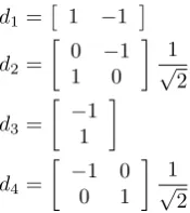
in the four orientations. The gradient filters are as follows:
d1=
1 −1
d2=
0 −1
1 0
1
√
2
d3=
−1
1
d4=
−1 0
0 1
1
√
2
(4)
[image:4.595.47.288.82.273.2]The resulting set of images is known as a gradient pyramid [5], and can completely represent the original image [10]. The gradient pyramid is essentially a set of gradient maps of the source images at varying scales. As illustrated in Fig. 2, the gradient pyramids constitute a large amount of intermediate data: each level of the two source pyramids is now represented by four gradient maps. Another way to conceptualise this is that the two source pyramids have now been decomposed into four further pyramids each, giving a total of eight full image pyramids to be handled and pro-cessed concurrently. Obviously, the ability to work with this amount of data on chip is one of the ways in which an FPGA may achieve large performance gains over a microprocessor based implementation.
Fusion of the gradient pyramids takes place by select-ing the most prominent detail from each level. In this ap-plication the elements with the greatest absolute value are chosen through a simple comparison, this is an implemen-tation of the simple measure of saliency given in [4]. Other, more complex measures of saliency (also known as Activity-Level Measurements [11]), based on texture criteria and other higher order attributes, may give better results in some specific circumstances, but the amplitude based measure has been shown to provide good results in the general case [4].
4. IMAGE RECONSTRUCTION
Before the inverse transform can take place it is necessary to adjust the format of the composite image pyramid, as the in-verse pyramid transform relies on the Laplacian rather than the Gaussian pyramid. The conversion requires a secondary application of the gradient filters, followed by summation and scaling; for a full description of the process see [5]. The output of this process is a composite Laplacian image pyra-mid that may be inverse transformed. The method of re-constructing an image from its Laplacian pyramid uses the
EXPANDoperation defined earlier. The starting point for the inverse transform is the top level of the Gaussian
pyra-mid (in this caseG5). This is formed by a simple averaging
of the top level of the source pyramids. Then, from (3):
˜
Gk = ˜Lk+EXP AN D(Gk+1) (5)
This process is performed repeatedly to expand each
pyra-mid level. The addition ofL˜k represents the incorporation
of detail data at each scale. The complete fused image lies at
the bottom of this pyramid, levelG0. This process mirrors
the decomposition process described in Section 2, and again uses FIFOs to store data between pyramid levels, with two-dimensional upsampling occurring as data are read from the FIFOs through insertion of zero value samples.
5. IMPLEMENTATION RESULTS
The entire design was implemented using Xilinx System Generator, and mapped to a Virtex-2 XC2VP100 device. Synthesis was carried out using Xilinx’s proprietary XST tool, as part of ISE8.1. The resource requirements are shown in Table 1. The large RAM requirement is mostly for the delay lines used in the 2D convolutions. The design is fully pipelined and capable of producing an output pixel every clock cycle. The maximum clock speed reported by the place and route tools is 31MHz.
As a means of comparing the system’s performance with a software implementation, the Matlab Profiler was used to measure the speed of execution of a Matlab implementation of the same algorithm. Processing a single frame of data on a 2.8GHz Pentium-4 processor with 1GB RAM takes, on average, 1.1 seconds. A comparison of the performance of both FPGA and PC based versions of the algorithm is shown in Table 2.
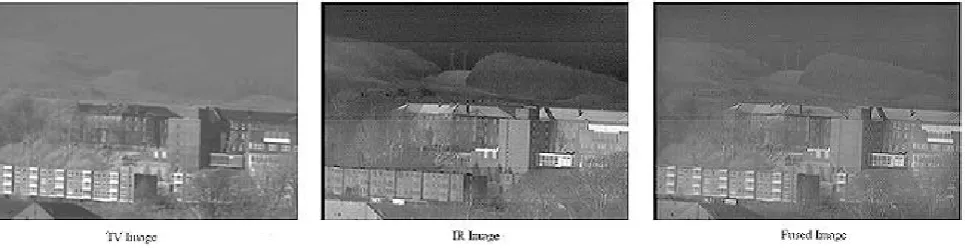
Note that although the maximum reported clock speed is 31MHz, a speed of 10MHz would allow 8-bit greyscale VGA video at 30fps to be processed in real-time, with a
la-tency of <50ms. Sample images have been produced for
[image:4.595.126.214.336.435.2]Fig. 3. Example of source and fused images.
Table 1. FPGA resource requirements
Resource Used Available % of XC2VP100
Slices 13,287 44,096 30
4-input LUTs 24,533 88,192 27
Slice FFs 5,784 88,192 6
Block RAMS 430 444 96
Table 2. Performance compared to PC implementation
FPGA Maximum Clock Frequency 31 MHz
FPGA Maximum Frame Rate (8-bit, VGA) 101 fps
PC/Matlab Frame Rate (2.8GHz P4, 1GB RAM)
0.91 fps
Speedup 111x
6. CONCLUSION
A complete implementation of pattern-selective image fu-sion has been presented that utilises aspects of FPGA tech-nology to enable dual video streams to be processed in real-time. Four levels of pyramidal decomposition, with four separate gradient operators, can all run on a single device with no requirement for off-chip memory. The modular na-ture of the design means that pyramids with less, or more, levels could be implemented without major modification. Use of an FPGA has enabled a design that can process im-ages at a rate over 100 times faster than a similar PC-based implementation.
7. ACKNOWLEDGEMENTS
The authors would like to thank Thales Optronics Ltd. and the Engineering and Physical Sciences Research Council (EPSRC) for their support under the Engineering Doctorate programme.
8. REFERENCES
[1] P. K. Varshney, “Multisensor data fusion,”Electronics and Communication Engineering Journal, vol. 9, no. 6, pp. 245– 253, Dec. 1997.
[2] Z. Xue, R. S. Blum, and Y. Li, “Fusion of visual and IR im-ages for concealed weapon detection,” inProc. 5th Int. Conf. Information Fusion, vol. 1, Sept. 2002.
[3] E. H. Adelson, C. H. Anderson, J. R. Bergen, P. J. Burt, and J. M. Ogden, “Pyramid methods in image processing,”RCA Engineer, vol. 29, no. 6, Nov. 1984.
[4] P. J. Burt, “A gradient pyramid-basis for pattern-selective im-age fusion,” inProc. Society for Information Display Conf., 1992.
[5] P. J. Burt and R. J. Kolczynski, “Enhanced image capture through fusion,” inProc. 4th Int. Conf. Computer Vision, May 1993, pp. 173–182.
[6] V. S. Petrovi´c and C. S. Xydeas, “Gradient based multireso-lution image fusion,”IEEE Trans. Image Processing, vol. 13, no. 2, pp. 228–237, Feb. 2004.
[7] P. Burt and E. Adelson, “The Laplacian pyramid as a compact image code,”IEEE Trans. Commun., vol. 31, no. 4, pp. 532– 540, Apr. 1983.
[8] G. S. van der Wal and P. J. Burt, “A VLSI pyramid chip for multiresolution image analysis,”Int. Jour. Computer Vision, vol. 8, no. 3, pp. 177–189, 1992.
[9] C. H. Anderson, “Filter-subtract-decimate hierarchical pyra-mid signal analyzing and synthesizing technique,” U.S. Patent 4 718 104, 1987.
[10] A. L. Abbot, P. M. Athanas, L. Chen, and R. L. Elliot, “Find-ing lines and build“Find-ing pyramids with Splash-2,” in Proc. IEEE Workshop on FPGAs for custom computing machines, Apr. 1994, pp. 155–163.
[image:5.595.61.544.82.206.2]