International Journal of Innovative Technology and Exploring Engineering (IJITEE) ISSN: 2278-3075, Volume-8 Issue-12, October 2019
Abstract: In this article, an optimized micro-strip patch antenna for vehicular communication is presented. It consists of rectangular radiating element with 50 Ω microstrip line feed. The FR-4 dielectric material is used as the substrate with relative permittivity of 4.4. ANSYS High Frequency Structure Simulator (HFSS) based on the Finite Element Method (FEM) is used to analyze the performance of the micro-strip patch antenna. Results show that the antenna operated at 5.9 GHz with return loss of -14.07 dB and Voltage Standing Wave Ratio (VSWR) of 1.13. The optimization of the antenna is carried out by employing the meta-heuristic algorithms such as Genetic Algorithm (GA) and Particle Swarm Optimization (PSO). PSO is implemented with the help of MATLAB and GA is performed by ANSYS optimetrics tool. After applying the optimization algorithms, performance of the antenna has been improved. The return loss and VSWR obtained from GA are -34 dB and 1.0 whereas from PSO are -20 dB and 1.65. On comparing GA and PSO, the results obtained from GA are better than PSO. The design methodology of micro-strip patch antenna and the employed optimization techniques are presented.
Keywords: Genetic Algorithm (GA), meta-heuristic, Optimization, Particle Swarm Optimization (PSO)
I. INTRODUCTION
I
n this current era of mobile communication, antennas play a major role in wireless devices. Antenna design has become more complex over the years with inherent tradeoff that exist between bandwidth, gain, radiation pattern and physical size. It makes the design of an antenna as a lengthy process [1-3]. In recent days, various methods have been used to optimize the antennas in order to enhance their performance. Some of the algorithms are Genetic Algorithm (GA) and Particle Swarm Optimization (PSO), which is also referred as meta-heuristic algorithms or evolutionary algorithms. The optimization of the antenna shape and size are performed by using GA that is one of the widely used global optimization algorithms. Natural selection, evaluation, crossover and mutation are the basic concepts of GA [4-5].The performances of the antennas are also improved by performing the optimization of resonant frequency, bandwidth, directivity, gain and size using GA [6]. Another
Revised Manuscript Received on October 05, 2019. * Correspondence Author
Palniladevi*, Assistant Professor / ECE department, Mepco Schlenk Engineering College, Sivakasi, Tamil Nadu, India. Email: [email protected]
Kalai Amutha, UG student ECE department, Mepco Schlenk
Engineering College, Sivakasi, Tamil Nadu, India. Email: [email protected]
Janani Priya, UG student ECE department, Mepco Schlenk Engineering
College, Sivakasi, Tamil Nadu, India. Email: [email protected]
computational method is PSO that helps to optimize a problem that constantly attempts to produce a best solution [7-9]. Here the particles are assumed to move around the search area for optimized result by updating their position and velocity. Recently PSO is capable of handling multiple design goals efficiently. Mathematical function of the desired parameters is taken as objective function [10-11]. In this paper, the performances analysis of micro-strip patch antenna is investigated by applying meta-heuristic algorithms such as GA and PSO.
II. MICRO-STRIPPATCHANTENNA
Micro-strip patch antennas are more popular because of its small size and ease of fabrication. However, it provides low bandwidth. The bandwidth of these types of an antenna can be improved by using optimization algorithms. Micro-strip patch antenna consists of dielectric material, radiating element and ground plane. Radiating element is placed on a top of the dielectric material and the ground plane is located at the bottommost. In some of the patch antennas, to achieve wider bandwidth dielectric spacers replace dielectric material. These antennas are incorporated into mobile radio communications and telecommunication devices because of its low profile. Generally, micro-strip antennas have the shapes of square, rectangular, circular and elliptical, but any continuous shape is possible. The rectangular shape is widely employed to realize the micro-strip antenna. Suppose air is taken as the dielectric substrate for design, the length of the rectangular micro-strip antenna is approximately one-half of a free-space wavelength. The electrical length of the antenna is extended due to the effect of fringing fields.
A. Micro-strip Patch antenna design and configuration The proposed antenna designed in HFSS17.0 is shown in figure 1. Here FR4 is used as the substrate of the antenna because it is cheap and easy to fabricate. The chosen dielectric height is 1.6 mm, dielectric constant is 4.4 and loss tangent is 0.02 and the resonant frequency is about 5.9GHz.The detailed parameters of the patch antenna are shown in the Table 1. The formulae to determine patch dimensions are as follows:
1
2
*
2
0
eff r
f
c
width
Design of an Optimized Micro-Strip Patch
Antenna
using Meta-Heuristic Algorithms
Palniladevi P, Kalai Amutha
K, Janani Priya P
L
f
c
Length
eff r
2
*
2
0
2 1
12
1
*
2
1
2
1
W
h
eff eff
eff
[image:2.595.52.292.58.327.2]
Table–1: Parameters of the patch
Parameters
L
p
W
pL
fW
fL
tW
tValues(mm) 10 11 6.97 3.05 12.71 0.8
Fig 1. Micro-strip patch antenna (a) Top view (b) Bottom view
III. GENETICALGORITHM
Holland and De Jong introduced the hypothesis of GA that contains the optimization search approaches and concepts based on natural selection and evolution. Figure 2 presents the functional block diagram for genetic algorithm. The first step of GA is the creation of initial population. Each individual in a population are coded as a string of bits, which is called as chromosome. A good chromosome is determined by the best value of objective function. Initially, the individuals are randomly generated.
Fig 2.Functional diagram of Genetic Algorithm The cost function or objective function is used to calculate the fitness of individual in the population. The new generation is formed by mating these individuals. The individuals who have higher fitness are chosen for reproduction. Crossover and mutation are used to allow the search of objective function. The best individuals are arrived into the next
generation without any change. This process is repetitively performed until it reached a stop criterion. While designing an antenna with the help of GA the output can be generations of desired radiation pattern, impedance matching, side lobe suppression. GA by itself is very robust and so automatically converges to the local minimum point and even initiation is not less required, the amount of design information is minimum.
A. Genetic algorithm implementation
The optimization steps for designing antenna are summarized as below:
Step 1: The parameter which has to be optimized is taken as a variable initially. Here the length and width of the patch are taken as „a‟ and „b‟
Step 2: The variable sweep is added in optimetrics for which different combinations are created.
Step 3: Run and analyze the performance. Step 4: Choose Genetic algorithm as optimizer
Step5: Set calculation range and condition for the desired goal ie.,S11.
Step 6: Desired cost function is chosen.
Step 7: Optimization is terminated when stopping condition is met.
B. Parameter 1: Return loss – Results (After and Before apply GA)
[image:2.595.303.550.422.729.2]The return losses of the conventional patch and optimized patch antenna are depicted in Fig.3 and Fig 4 respectively.
Fig 3. Return loss of conventional patch antenna
Fig 4. Return loss of optimized patch antenna
Freq = 5.9 GHz R.L = -14.07dB
[image:2.595.78.267.536.676.2]International Journal of Innovative Technology and Exploring Engineering (IJITEE) ISSN: 2278-3075, Volume-8 Issue-12, October 2019
The above result shows that the S11value has been enhanced to
-34.16dB resonating at 6GHz.
C. Parameter 2: VSWR – Results (After and Before apply GA)
[image:3.595.313.538.117.332.2]The VSWR of the conventional patch optimized patch are depicted in Fig.5 and Fig 6 respectively.
Fig 5. VSWR of conventional patch antenna (1.13)
Fig 6. VSWR optimized patch antenna (1.0) Standing wave ratio is always minimum in design process. By comparing above two results, after optimized produce a good reduce in voltage standing wave ratio level this mean after optimization interference is properly avoided.
IV. PARTICLESWARMOPTIMIZATION Particle Swarm Optimization (PSO) is formulated by Kennedy and Eberhart. This algorithm is inspired by social behavior of birds and shoals of fish. PSO is a population based optimization which is non-deterministic and its performances are comparable to genetic algorithm. To find the best solution in PSO, swarm of particles is moving around the search space. The particles in the search space adjust its position and velocity based on its own behavior and the behavior of other particles. PSO adopts three methods namely
i) Separation – To avoid crowding among the particles. ii) Alignment – Moving towards the average head particle.
iii)Cohesion - Towards the average position of swarm.
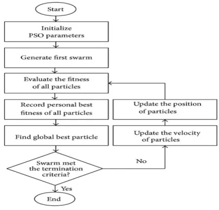
A. PSO Algorithm Implementation
[image:3.595.51.291.160.457.2]The design and configuration are same as that of GA but the software here used is MATLAB 2018a. The flow chart for PSO is presented in Fig 7.
Fig 7: Structural flow chart of PSO
Step 1: Define dimension of the problem, solution space, objective function and population size.
Step 2: Initialize population (X), velocity (V=0), personal best (pbest=X)
Step 3: For each iteration Step 3.1: For each particle
Evaluate objective function Update pbest
End
Step 3.2: For each particle
Find best local guide in search space Update velocity
Update position End
Step 4: Check for the termination criteria B. PSO mathematical equations
The equation of velocity updation and position updation by particle i of component j is given by
t
IV
t
R
A
G
t
P
t
R
A
G
t
P
t
V
ij
1
ij
1 1 ij
ij
2 2 j
ij
t
1
P
t
V
(
t
1
)
P
ij ij ijWhere
t
V
ij - represents last velocity
t
1
V
ij - represents updated velocity
t
P
ij - represents last position
t
1
P
ij - representsupdated position
I - represents inertia coefficient
A1 A2 - represents acceleration coefficient R1R2 - represents random number (0-1)
[image:4.595.304.555.61.224.2]The new velocity translates the position to a new position in the search space.
Fig 8: Velocity and Position updating of PSO
C. PSO objective function
The objective function chosen is given below
2
arg 2
arg
*
*
f
cf
ct etQ
BW
BW
t etP
sqrt
x
F
where P and Q represent biasing constant to control the impact of fctarget and BWtarget. The resonant frequency and
required bandwidth are denoted by fc and BW. If the constant P is increased, the PSO is biased to optimize the antenna towards the resonant frequency. In case of increase in the value of Q, the bandwidth of the antenna is optimized by PSO.
D. Parameter 1: Return loss– Results (After and Before apply PSO)
[image:4.595.59.276.125.272.2]The return losses of the conventional patch and optimized patch antenna using PSO code in Matlab are shown in Fig.9 and Fig.10 respectively.
Fig 9. Return loss plot for conventional patch antenna design using Matlab (run at 6GHz is -10dB) The above result shows the return loss of Micro-strip patch antenna at 6GHz by simulating in matlab, here taking all the frequencies return loss value of this patch antenna are considered as a swarm in PSO. Besides evaluate the fitness of a swarm particles and find the best solution.
Fig 10. Return loss of optimized patch antenna design using Matlab (run at 6GHz is -21.00dB) E. Parameter 2: VSWR– Results (After and Before apply PSO)
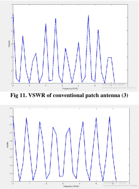
[image:4.595.305.549.318.649.2]The VSWR of the conventional patch and optimized patch antenna using PSO code in Matlab are shown in Fig.11 and Fig 12 respectively.
Fig 11. VSWR of conventional patch antenna (3)
Fig 12. VSWR of optimized patch antenna (1.65)
[image:4.595.47.291.562.698.2]International Journal of Innovative Technology and Exploring Engineering (IJITEE) ISSN: 2278-3075, Volume-8 Issue-12, October 2019
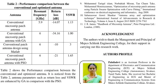
Table 2 : Performance comparison between the conventional and optimized antenna Antenna
Resonant frequency [GHz]
Return loss [dB]
VSWR Conventional
microstrip patch antenna
5.9 -14.07 1.13
Conventional microstrip patch antenna with GA
6 -34.16 1.00
Conventional patch antenna design using
Matlab
6 -10 3
Conventional microstrip patch antenna with PSO
6 -21 1.65
Table 2 shows the Performance comparison between the conventional and optimized antenna. It is noticed from the Table 2, antenna parameters such as return loss and VSWR are enhanced by GA in comparison with the PSO.
V. CONCLUSION
In this work, a microstrip patch antenna with Genetic algorithm and Particle Swarm Optimization has been presented for vehicular communication. ANSYS HFSS is used for analyzing the characteristics of antenna. MATLAB2018a and ANSYS optimetrics tool are utilized for implementing the algorithms to obtain the optimal results. The micro-strip antenna with GA exhibits returns loss of -34 dB and VSWR of 1.0 at 5.9 GHz. Meanwhile, return loss and VSWR of micro-strip antenna with PSO are -20 dB and 1.65. The simulated results are revealed that the Genetic Algorithm yielded good results in terms of return loss and VSWR than the PSO.
REFERENCES
1. Tahsin Ferdous Ara Nayna , A. K. M. Baki , Feroz Ahmed ”Comparative Study of Rectangular and Circular Microstrip Patch Antennas in X Band”, International Conference on Electrical Engineering and Information & Communication Technology (ICEEICT) 2014. 2. Lo, T. K. and Y. Hwang, “Microstrip antennas of very high permittivity
for personal communications,” Asia Pacific Microwave Conference, Vol. 1, 253–256, 1997.
3. Elftouh, H., N.A. Touhami, andM. Aghoutane, “Miniaturized microstrip patch antenna with spiral defected microstrip structure,” Progress In Electromagnetics Research Letters, Vol. 53, 77–44, 2015.
4. Mohammed Lamsalli, Abdelouahab El Hamichi, Mohamed Boussouis, Naima A. Touhami, and Taj-eddin Elhamadi “Genetic Algorithm Optimization for Microstrip Patch Antenna Miniaturization” Progress In Electromagnetics Research Letters, Vol. 60, 113–120, 2016
5. Jayasinghe, J. M. J. W., J. Anguera, and D. N. Uduwawala, “Genetic algorithm optimization of a high-directivity microstrip patch antenna having a rectangular profile,” Radio engineering, Vol. 22, No. 3, 1–4, 2012
6. Vincens Gjokaj, John Doroshewitz, Jeffrey Nanzer, and Premjeet Chahal “A Design Study of 5G Antennas Optimized Using Genetic Algorithms” 2017 IEEE 67th Electronic Components and Technology Conference.
7. Dr. Sunil Kumar, Atul Mishra, Gurjeet Singh, “Review on PSO based micro strip patch antenna for Ku-Band application,” Radio engineering, Vol.03, Issue 06, June 2016.
8. Anthony A Minasian, Trevo S Bird, “Particle Swarm Optimization of microstrip antennas for Wireless Communication Systems,” IEEE Transaction for antenna and propagation, Vol. 61, No.12,Dec 2013.
9. Mohammed Tariqul islam, Norbahiah Misran, Tan Chuen Take, Mohammed Moniruzzaman, “Optimization of microstrip patch antenna using Particle Swarm Optimization with Curve Fitting,” International conference on electrical engineering and informatics, Aug-2009. 10. Sabareeswar Gowri Shankar “Antenna array and optimization
technique” International Journal of Advancements in Research & Technology, Volume 4, Issue 8, August 2015 ISSN 2278-7763 11. J. R. James, “Handbook of Microstrip Antenna”, Peter Peregrinus Ltd.:
London, (1989).
ACKNOWLEDGMENT
The authors wish to thank the Management and Principal of Mepco Schlenk Engineering College, for their support in carrying out this research work.
AUTHORSPROFILE
Palniladevi is an Assistant Professor in the department of Electronics and Communication Engineering (ECE) at Mepco Schlenk Engineering College (Autonomous), Sivakasi, Tamil Nadu, India. She received her Bachelor of Engineering in ECE and Master of Engineering in Communication Systems from Mepco Schlenk Engineering College, Sivakasi. She is a life time member of ISTE and IETE. She has published 7 research articles in various international journals and conferences. Her current research interest includes antenna design and wireless communication.
Kalai Amutha pursing final year Bachelor of Engineering in the department of Electronics and Communication Engineering (ECE) at Mepco Schlenk Engineering College (Autonomous), Sivakasi, Tamil Nadu, India. She is a life time member of ISTE Student chapter. Her project interest includes antenna design.
[image:5.595.45.554.44.315.2]