A Comprehensive Simulation Platform for Switched Reluctance
Generator System
A.ARIFIN, I.H.AL-BAHADLY, S.C.MUKHOPADHYAY
School of Engineering and Advanced Technology
Massey University
Tennet Drive, Palmerston North 4474
NEW ZEALAND
{a.arifin, I.H.AlBahadly, S.C.Mukhopadhyay}@massey.ac.nz
Abstract: - A Switched Reluctance Generator (SRG) system normally encompasses three main components: SR machine, controller and converter. On-going research on simulation and modelling of SRG system has focused on one component. There is a lack of a more comprehensive approach which integrates all three components into one simulation platform. We have developed a simulation model comprising SR machine, control and converter using MATLAB/Simulink. The main advantage of a simulation model is to reduce time and cost by having to perform changes on the prototype machine. In this paper, the work is focused on developing the optimal control algorithm for the platform. Optimal parameters are identified and characterized in terms of highest percentage of power generated. From simulation, the most influential parameters affecting the power generated are the firing angles and voltage level. So, a function relating the optimized parameter with machine performance was developed. The proposed control technique will provide easy implementation and ensure high machine performance. The effectiveness of the proposed method is demonstrated by simulation results. The work will aid in development of SRG by providing a platform to determine the best generating operation before real implementation, reducing manufacturing time and cost.
Key-Words: -Current control, Finite Element Method, Optimization, Simulation of SRG drive, Switched reluctance generator (SRG), SRG control.
1 Introduction
The use of the Switched Reluctance Machine (SRM) as a motor has been well established. It has been around in the domestic industry in appliances such as vacuum cleaners and washing machines. In the automotive industry, the SR machine is used in hybrid buses, truck starter generators and also in car starter generators. The SR machine can also be operated as a generator, where it is mainly used in high speed application as starter/generator for aircraft and gas turbines. The structure of the machine and its inherent capability to start with low inertia has made researchers realize the potential of the machine to operate in a wide speed range. So its adaptability is now being applied in wind energy field. With the increase in environmental awareness, and growing demand for energy, a supply that is sustainable with the least environmental impact is the focus of study. Amongst the growing potential of renewable energy nowadays is the wind energy which accounts for the 3% of the world’s electricity demand. The on-going studies regarding the use of the switched reluctance generator (SRG) in wind energy application proves it as a potential candidate alongside the conventional machines [1-4]. The
research however, is limited to exploring the different types of control for operation of SRG in variable speed applications.
There are also studies in the area of optimal control, machine structure and converter requirements [5, 6]. In [7-11], investigations on the number of stator and rotor poles on machine performance have been made. They have come to an agreement that a low number of poles is for high speed application whereas a high number of poles relates to low speed application. However, at this stage of the research there is no right combination which gives optimum performance
.
application. Iterative method to identify and classify design parameters based on its application in high speed range has also been studied [14]. But this did not include any development of function or procedure relating the optimized parameters with machine performance. For those reported methods, the research is limited to high speed operation. Only [15] has reported on optimization during current controlled operation. Although different control strategies have been proposed, the common features amongst these studies in the literature are focused on the optimization of firing angles in terms of minimizing losses.
The conventional excitation circuit used for SRG is the asymmetric half bridge converter (AHBC). However, studies have been undertaken to minimize cost by reducing the number of components in the converter circuit [16, 17]. The best option for the converter to be used has yet to be defined.
While a number of papers on SRG in wind energy applications have been published, the existing research focused on individual element of the drive system to achieve optimal performance. To date there is no specific configuration of SRG that has been proposed to produce maximum output power. To address this issue, we look into the overall performance of the system taking into account the control variables, the machine structure and the converter.
Different from previously reported objectives, the aim of this study is to create a platform to analyse machine performance, so as to determine and characterize the optimal variables by investigating the impact of the controlled variables/parameters in terms of power generated by the machine. A control algorithm is proposed to perform dynamic control and optimize machine performance. A high percentage of generated power can be achieved by adjusting the terminal voltage level and operating the machine in single pulse mode during low speed range. The simulation work demonstrates that the model and proposed method can be used to aid in selecting the best/optimal operation of SRG for wind energy application.
2 Characteristics
of
Generating
Operation of Switched Reluctance
Generator Drives
In general, the SRM is a double salient machine where both its stator and rotor poles protrude into the air gap. It does not have any windings or magnets on the rotor poles. The rotor is simply
made of a stack of laminated iron steel. SRM’s have independent phase windings on the stator poles.
The machine operates in such a way that the rotor will move to the position of minimum reluctance. The rotation of the rotor is achieved by energizing and de-energizing the phase winding on the stator poles. When the windings are energized, the stator pole behaves as an electromagnet pulling the rotor towards the excited phase.
The stator phase is energized in synchronism with the rotor position to ensure continuous rotation. When rotor moves towards the stator pole, torque will be produced and there is a change in reluctance of magnetic path. Whenthe rotor is aligned with the stator pole, reluctance is minimum, whilst inductance is maximum. As the rotor moves away from the stator pole, the air gap increases and inductance starts to decrease. During the unaligned position, inductance will be at its minimum value. By proper excitation of phase winding, the machine can operate as a motor during the increasing inductance region, and as a generator during the decreasing inductance region. To operate the machine as a generator, the windings are excited as the rotor is moving away from the stator poles.
2.1 Current Waveforms of a three phase
SRG
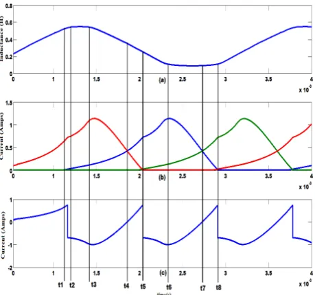
The analysis of the phase current waveform is best described through the position of firing angles on the inductance profile. Previous research to optimize firing angles uses idealized inductance waveform as well as looking into one cycle of operation [18, 19]. This analysis will consider overlapping area when all three phases operates as in Fig. 1.
The existence of control intervals in SRG operation requires the best selection in firing angles. It is not a straight forward procedure since the machine is highly nonlinear with both its flux linkage and inductance varying as a function of current and rotor position. Also the machine is singly excited and may produce a discontinuous current profile. Several factors affect the angle selection:
inductance slope, more energy is stored in the winding hence more power will be generated. However, this leads to the generating current tailing off in the next phase of excitation causing overlap between the adjacent phases. Overlap is required to produce a continuous current profile.
• Back EMF during the generating operation will assist in the increase of current in phase winding, thus increasing power generated. The voltage across phase winding during the excitation and generation stage is as follows:
θ
ω
d
dL
i
dt
di
L
Ri
V
=
+
+
±
(1)
where V is the terminal voltage, R is the phase resistance and inductance L, is a function of both phase current i and rotor position θ The terminal voltage will be negative during generating due to the freewheeling current through the diodes. Using the separation of variable method to equation (1), phase current is analysed
:
t
d
dL
R
L
Vt
i
))
(
(
θ
ω
±
+
+
±
=
(2)
Conditions which may occur during the excitation and generation stages depend on the slope of inductance and amplitude of terminal voltage and back EMF.
In Fig. 1, two modes of operation occur during the time period t1-t5: energy in phase winding one
(Ph1) is released through the diodes whilst current in phase winding two (Ph2) starts excitation stage. Voltage across Ph1 is negative, therefore current ascends to zero. Ascending velocity depends on voltage, back EMF and also on the amount of energy stored during excitation. When current in Ph1 is more than current in Ph2, generating current dominates in the dc link line as shown in Fig. 1(c). Terminal voltage also contributes to the increase of power generated. If turn on angle is made prior to poles alignment, higher voltage is required to push current to its maximum value.
Based on the above analysis, the factors which may increase current are speed, voltage, placement of firing angles and also the reference current. These parameters will be analysed in order to determine its best/optimal operating parameter at each speed range.
As can be seen, it is not a straight forward procedure to determine optimal parameters for SRG. After turn off angle, phase current may increase or decrease depending on the amount of stored energy and back EMF as shown in Fig. 2. Also the peak of phase current cannot be predicted. Therefore, the only way to determine the optimal range of parameters is by the heuristic method. Then, the relations between the optimal parameters and machine performance can be developed.
2.2
Criteria for Generating Operation
One criterion has been identified based on the operation of the generator to maximize power generation. The maximum percentage of power generated is evaluated through:
0 0.5 1 1.5 2 2.5 3 3.5 4
x 10-3 0
0.2 0.4 0.6 0.8 1 1.2 1.4
time (s)
C
u
rr
e
n
t
(A
m
p
s
)
Ton=27 (b)
Toff=35deg
Ton=19 (d)
Ton=25 (c)
Ton=28 (a)
[image:3.595.49.279.504.719.2]Fig. 2 Variation of phase current with respect to inductance profile for various turn on angle and constant turn off angle of 350 at 200V and speed of 300rad/s
[image:3.595.313.546.548.701.2].
%
_
100
.
.
gen gen
gen gen exc exc
v
i
gen
power
v
i
v
i
=
×
+
(3)
where
v
gen,v
exc are the average generated andexcitation voltages,
i
gen,i
excare the averagegenerated and excitation currents. Total lossesin the machine including copper and iron loss, should be considered for the optimization. In this study the optimization is carried out for each value of reference current, voltage and speed. Hence iron loss which depends on flux density and frequency is assumed constant. Iron loss becomes the dominant component of losses at very high speed [20]. This study is focused on wind energy which is categorised under low and medium speed range; therefore only copper losses are included in the calculation since they vary with phase current. The average power including copper loss for the three phase machine is computed for one cycle of phase current, T using instantaneous voltage and current:
) ) (
1
( 2
0
dt R i Vi T P
T
total =
∫
−(4)
Having a high percentage of power generated implies that the losses are minimized. The effect of variable parameters on the criteria above aids in developing a control method to optimize the generating operation of the machine.
3 Generator Modeling
The model is formed based on electromagnetic characteristics of the machine. These characteristics are obtained via finite element (FE) analysis. An experiment was set up to verify and validate the results obtained using FE method. The magnetization curves of flux linkage versus current for each rotor position were obtained. This will be the key component to determine other parameters such as: i matrix, co-energy, torque and also inductance. The calculation of the magnetic characteristics was detailed in a previous paper [21].
The nonlinearity of the machine provides a challenge in modelling and analysis owing to the doubly salient structure and its operation in the magnetic saturation region. The intention to operate the machine under magnetic saturation is to achieve high efficiency. Thus, to analyse and predict the performance of the generator, a platform to change the generator parameter is essential.
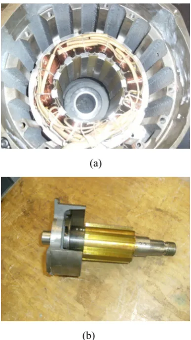
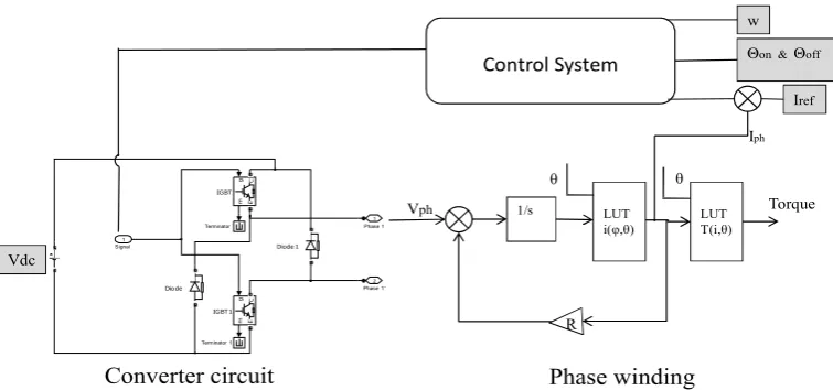
This paper considers a three phase 12/8 machine as shown in Fig. 3 whose parameters are listed in Table 1. As mentioned earlier, the proposed SRG drive system is to aid in determining the machine performance before building the prototype. The switched reluctance generator can be represented as a mathematical model comprising electrical and mechanical sections. An asymmetric half bridge converter (AHBC) circuit and hysteresis current controller areemployed for this study. The complete SRG drive can be integrated as in Fig. 4.
(a)
(b)
[image:4.595.333.527.74.419.2]Fig. 3 Configuration of a 3 phase 12/8 machine under study (a) stator (b) rotor
Table 1. SRG parameters Rotor pole pitch 450 Phase winding resistance, Rph 9.85Ω
Number of rotor pole, Nr 8
Number of stator pole, Ns 12
[image:4.595.49.285.79.482.2]Phase 1' 2 Phase 1
1
Terminator 1 Terminator
IGBT 1
g
m
C
E
IGBT
g
m
C
E
Diode 1
Diode
Signal 1
Control System
w
Converter circuit Phase winding
1/s LUT
i(φ,θ)
LUT T(i,θ)
Vph Torque
θ θ
Θon & Θoff
Vdc
Iref
Iph
R
Fig. 4 Complete model of SRG drive including machine, converter and control system using MATLAB/Simulink.
4 Algorithm for Control Optimization
As stated in Section 2.1, there is no procedure to identify optimal angles due to the nonlinearity behaviour of the machine. The occurrence and increase of peak current after turn off angle cannot be predicted; therefore there will be an optimal angle which will produce the maximum generated current.The amount of power generated is dictated by the shape of phase current and placement of firing angles on the inductance slope.
In order to determine the highest percentage of power generated, the generator model is simulated for all possible combinations of turn on angle, θon and turn off angle, θoff in increments of 1 degree at speeds in the range of 25rad/s to 500rad/s. The speed range is strategically selected to represent low and high speed. The optimal combination of θon and θoff are selected for each speed and voltage level. The criterion is to determine the angle which gives the highest percentage of generated power. All the selected optimal angles for each speed and voltage range are compiled and the algorithm to select the optimal parameters is developed.
4.1 Low speed
Conventional control strategies employ current chopping for low speeds, whereas single pulse mode is used for high speed operations. This current chopping will hold the current constant for a specified amount of time resulting in a constant power output. It is useful for the motoring operation where it provides mechanical energy to a load. As for the generating operation, the aim of this work is to focus on maximizing the generated power at any
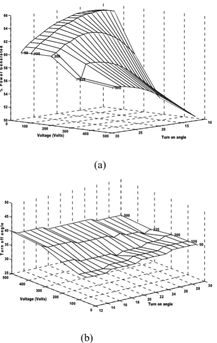
speed range. Hence, current chopping is not suitable as the chopping frequency reduces the amount of energy captured. Therefore to avoid the chopping action, voltage level is varied to allow single pulse mode operation in the low speed range. Fig. 5(a) shows that the percentages of power generated by shaping the current in a single pulse mode as opposed to current chopping are higher. It also shows that an optimal turn on angle exists at each voltage level and speed. The turn off angle does not change much as depicted in Fig. 5(b).
4.2
High speed
[image:5.595.119.497.78.255.2]10 15 20 25 30 0 100 200 300 400 500 50 52 54 56 58 60 62 64 66
Turn on angle
←500 ←325 ←200 ←100 ←50 % P o w e r G e n e ra te d Voltage (Volts)
(a)
12 14 16 18 20 22 24 26 28 30 0 100 200 300 400 500 25 30 35 40 45 50 ←50 ←100 ←200 ←325
Turn on angle
[image:6.595.56.280.77.431.2]←500 Voltage (Volts) T u rn o ff a n g le (b)
Fig. 5 Variation of (a) percentage power generated versus turn on angle and (b) turn off angle versus turn on angle at low speed of 35rad/s
Fig. 7 Graph showing relationship between dwell angle with speed and voltage level. The range of speed is between 25rad/s to 500rad/s at voltage level between 100V to 500V
4.3
Discussion
Having identified the range of optimal parameters, it can be categorized as in Table 2 for low speeds ranging from 25 to 55rad/s and Table 3 for high speeds ranging from 100 to 500rad/s. The bold values in Table 2 show the optimal angles which produce the continuous current profile taken at full overlap of phase current.
It can clearly be seen that by changing the voltage level, the total amount of power generated changes. Fig. 8 shows the profile of phase current at its
optimal angles at the speed of 35rad/s at 100V and 325V. A current chopping profile will produce a lower percentage of power generated compared to the single phase mode. Therefore to optimize the performance of the machine in the speed range 25rad/s to 55rad/s, a voltage level below 200V is selected. The current profile at the higher speed of 500rad/s for all voltage level at its optimal angles is shown in Fig.9.The current profiles are smoother for voltage levels between 100V to 200V. At higher voltages, more power can be generated at the
expense of having more noise. Since the difference in percentage of power generated at high speed is small although voltage level is changed, the choice of voltage will depend on the type of application.
The percentage of power generated for speed in 10 12 14
16 18 20 22 24 0 200 400 600 72.5 73 73.5 74 74.5 75 75.5 76 76.5 ←50 ←100 ←200 ←325 ←500
Turn on angle Voltage (Volts) % p o w e r g e n e ra te d (a)
10 12 14 16 18 20 22 24 0 100 200 300 400 50030 32 34 36 38 40 ←50 ←100 ←200
[image:6.595.318.541.85.406.2]Turn on angle ←325 ←500 Voltage (Volt) T u rn o ff a n g le
(b) [image:6.595.316.541.547.705.2]
Table 2. Optimal angles at low speed and voltage Volt Turn
on on
θ
Turn off offθ
Dwell ( offθ
-onθ
) dθ
Total Instantane -ous Power Instantan -eous Copper losses ω=25rad/s50V 16 34 18 51.7 15.3
100V 18 34 16 196.6 56.2 200V 26 36 10 497 86.76 325V 29 37 8 933.8 111.7
19 41 22 1247.9 173.8
500V 31 38 7 1662.7 140.7
21 41 20 2085.1 194.6
ω=35rad/s
50V 16 35 19 45.7 12.7 100V 15 34 19 178 47.4 200V 22 35 13 485.8 84.15 325V 27 36 9 846.4 93.8
17 42 25 1171.5 159.3
500V 29 37 8 1531.7 121.9
22 42 20 1951.5 177.8
ω=45rad/s
50V 15 35 20 39.7 9.7 100V 13 34 21 160.9 39.6 200V 18 34 16 497 91.35 325V 24 36 12 849.5 96.1
16 43 27 1098.4 145.7
500V 28 37 9 1460.2 112.7
19 42 23 1858.5 166.6
ω=55rad/s
50V 14 35 21 35.3 7.8 100V 14 35 21 144.8 33.5 200V 16 34 18 498.5 95.54 325V 21 36 15 845.2 96.3
13 43 30 1052.7 136.2
500V 26 37 11 1414.8 109.8
17 42 25 1794.4 158.8
the range of 25rad/s to 55rad/s using voltage level more than 325V is below 60%. Hence the optimal voltage for low speed can be grouped as in Table 4. The selection of the optimal voltage is compromised in terms of percentage of power generated and the total instantaneous power during one phase cycle. For speeds 25rad/s and below, 100V is chosen as the optimal voltage level as opposed to 50V since the difference in percentage of power generated is less than 1%. Also, it gives higher ratio of total amount of power generated by 3.8. It shows that by increasing the voltage level, more power is generated even though the percentage of power generated does not show significant change
The same goes for high speeds in the range between 100 to 500rad/s, where the percentage of power generated is almost the same, even though the voltage level has been changed. Based on the current profile, the optimal voltage level can be grouped into three categories: low noise with high percentage of power generated, low noise with moderate amount of power generated and high noise with high generated power.
The voltage level which is categorised under low noise gives smoother current profile between 100V to 200V as in Fig. 9. Its percentage of generated power is in the range of 70%. Within this range, the amount of generated power differs. The voltage which generates the highest amount of power is 200V.
[image:7.595.313.559.76.478.2]In the second category, the 325V has better current profile as seen in Fig. 9. However, at 500V a significant amount of power generated can be seen. The ratio of power generated by 500V and 325V for speed above 200rad/s is approximately 2.4. This Table 4. Characterization of voltage level in the
speed range 25rad/s to 100rad/s
Speed, ω, (rad/s) Voltage(volt)
25rad/s ≤ ω 100V
25rad/s˂ω˂100rad/s, 200V
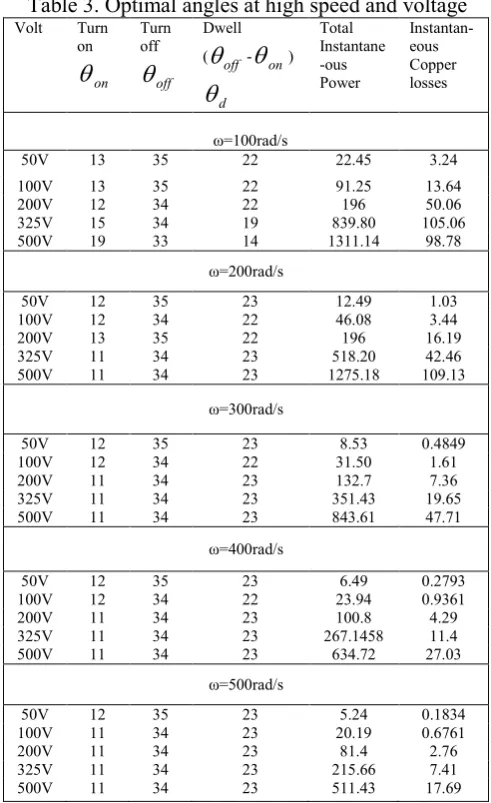
Table 3. Optimal angles at high speed and voltage Volt Turn
on on
θ
Turn off offθ
Dwell ( offθ
-onθ
) dθ
Total Instantane -ous Power Instantan-eous Copper losses ω=100rad/s50V 13 35 22 22.45 3.24
100V 13 35 22 91.25 13.64 200V 12 34 22 196 50.06 325V 15 34 19 839.80 105.06 500V 19 33 14 1311.14 98.78
ω=200rad/s
50V 12 35 23 12.49 1.03 100V 12 34 22 46.08 3.44 200V 13 35 22 196 16.19 325V 11 34 23 518.20 42.46 500V 11 34 23 1275.18 109.13
ω=300rad/s
50V 12 35 23 8.53 0.4849 100V 12 34 22 31.50 1.61 200V 11 34 23 132.7 7.36 325V 11 34 23 351.43 19.65 500V 11 34 23 843.61 47.71
ω=400rad/s
50V 12 35 23 6.49 0.2793 100V 12 34 22 23.94 0.9361 200V 11 34 23 100.8 4.29 325V 11 34 23 267.1458 11.4 500V 11 34 23 634.72 27.03
ω=500rad/s
[image:7.595.48.288.83.476.2]Fig. 8 Current profile using optimal angles at 100V and 325V at speed of 35rad/s
.
shows that the voltage level can be selected according to the type of application and area where it is to be implemented. The optimal voltage for high speed range is categorised as in Table 5.
5
Proposed Control Scheme
From the above investigations, we can conclude that the percentage of power generated is a function of firing angles and speed for different voltage level.
( , )
gen gen
P =P
θ ω
(5)
Also it should be pointed out that the change in turn on angle is more prominent as opposed to turn off angle. Therefore turn on angle can be changed, whereas turn off angle is held constant. The angle can be represented in terms of optimum dwell angle,
θdwell. The function will be represented according to
the optimal voltage level as in Table 4 and Table 5. Since there is an increase in dwell angle for speed below 55rad/s and a steady value for speed higher than 200rad/s, the function of dwell angle in terms of speed is represented using the Sigmoidal Model.
This model retains a steady value of dwell angle at higher speeds as compared to the third order equation, where a slight deviation can cause current to offset due to the oscillating behaviour.
d c
dwell
a
be
ω
θ
=
−
−(6)
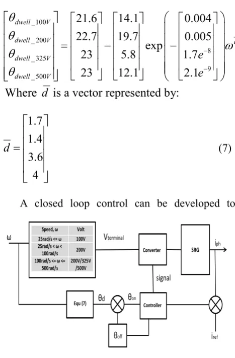
ω is the speed in rad/s and a, b, c and d are the coefficients determined using curve fitting procedure. The matrix representation of equation (7) is shown as:
_100 _ 200
8 _ 325
9 _ 500
21.6
14.1
0.004
22.7
19.7
0.005
exp
23
5.8
1.7
23
12.1
2.1
dwell V
dwell V d
dwell V
dwell V
e
e
θ
θ
ω
θ
θ
−
−
=
−
−
Where
d
is a vector represented by:
1.7 1.4 3.6 4
d
=
(7)
[image:8.595.314.541.83.212.2]A closed loop control can be developed to Fig. 9 Current profile using optimal angles at speed of 500rad/s for all voltage level.
Speed, ω Volt 25rad/s <= ω 100V 25rad/s < ω <
100rad/s 200V 100rad/s <= ω <=
500rad/s 200V/325V
/500V
θoff
Vterminal
ω
θd θon
SRG
Equ (7)
iph
Converter
Controller
signal
iref
[image:8.595.56.277.117.267.2]Fig. 10. Schematic diagram of the proposed control algorithm
Table 5. Characterization of voltage level in the speed range 100rad/s to 500rad/s
Speed, ω, (rad/s) Voltage(volt) 100rad/s ≤ ω≤500rad/s 200V
100rad/s˂ω˂500rad/s
(Moderate amount of generated power with low noise)
100rad/s˂ω˂500rad/s
(High generated power at the expense of higher noise level)
325V
[image:8.595.310.544.378.734.2] [image:8.595.51.287.593.744.2]provide the optimal dwell angle for speeds ranging from 25rad/s to 500rad/s. Fig. 10 illustrates the proposed control scheme to implement the control algorithm. The scheme is simple to implement since it does not include any additional/complicated circuitry. Based on the speed range, the controller will switch to the optimal voltage level that has been set. In this way, the machine can accommodate a change in wind velocity and provide the highest percentages of generated power.
6
Verification through Simulation
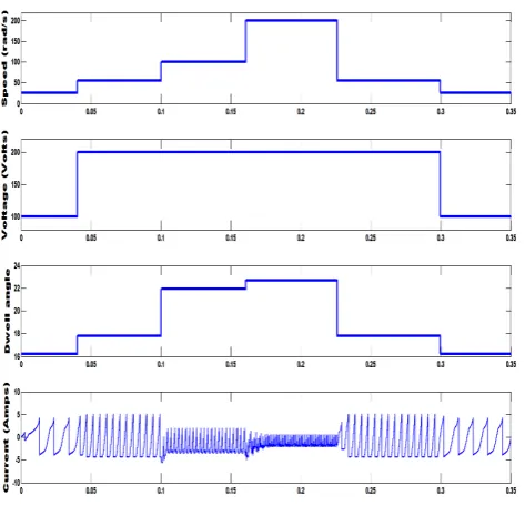
The algorithms proposed in Section 5 were implemented in simulation to confirm proper operation before it is developed experimentally. Since the SRG is intended for wind energy applications, the focus is to maximize the power generation as much as possible during any speed range. Fig. 11 shows the result when a step input speed is applied.
The proposed algorithm adjusts to the required voltage level in order to provide high percentage of generated power. The control technique provides the highest percentage of power generated by varying the voltage level within the speed range. Fig. 12 shows results of the implemented control technique which corresponds well with the results obtained using massive simulation.
7 Conclusion
Overall, the previous studies have acknowledged the potential of the SRG as one of the candidates for variable speed applications. However, the available research in the generating operation mainly covers the high speed application. Unlike its motoring counterpart, the commercial application of the machine as a generator is still limited.
The development of the SRG lacks a platform which enables researchers to perform analysis on the overall system before developing the machine prototype. To aid in the development of the SRG and to close the commercial gap between the existing machines a simulation platform of the overall system is required.
[image:9.595.50.287.75.303.2]In this study, a platform to study and analyse the performance and behaviour of the overall switched reluctance drive has been developed. It greatly reduces time and cost by having to set up and make changes on the real/prototypemachine. In this paper the control algorithm for the platform is proposed. From the simulation, optimal parameters have been Fig. 11. Simulation result of the proposed algorithm
when a step input is applied. The speed range was tested at 25rad/s-55rad/s-100rad/s-200rad/s-55rad/s-25rad/s.
0 50 100 150 200 250 300 350 400 450 500 12
14 16 18 20 22 24
Sigmoidal model simulation
(a)
0 50 100 150 200 250 300 350 400 450 500 60
62 64 66 68 70 72 74 76 78
Sigmoidal Model Simulation
(b)
[image:9.595.317.528.80.396.2]identified based on the criteria of high percentage of power generated. To ensure continuous current profile, the overlap between adjacent phase current has been taken into account. From simulation, the most influential parameters affecting the power generated are the firing angles and voltage level. Therefore, all the optimal parameters have been characterised according to each speed range and voltage level.
The optimal level of voltage for the low speed range between 25rad/s to 55rad/s is 100V to 200V. The percentage of power generated reduces to below 60% if higher voltage is used. At higher speeds between 100rad/s to 500rad/s, the optimal voltage level can be grouped into:
• high percentage of power generated with low noise
• moderate amount of power generated with low noise
• high generated power with high level of noise
As opposed to the conventional current chopping mode, the performance of the machine at a low speed is improved by operating the machine in single pulse mode. This is achieved by adjusting to the optimal voltage level within the speed range. The selection of voltage level can be made according to the type of application and the location of machine. Since the turn off angles remain almost constant, the relation of percentage of power generated can be represented as a function of dwell angle and speed at different level of voltage.
The simulation results have demonstrated that the proposed algorithm can be used to provide highest percentage of power generated. Therefore, the findings in this paper will aid in development of SRG by allowing user to choose the best generating operation within any speed range.
The research on improving the performance of the SRG is far from exhausted. It has taken years of research before the existing generators penetrates the market, the same will be for the new generations of machine. Further research is required to fill the commercial gap with the SRG and with the aid of a modelling software, an in depth analysis of SRG will improve its performance and acceptance.
References:
[1] Q. Bingni, S. Jiancheng, L. Tao, and Z. Hongda, "Mutual coupling and its effect on torque waveform of even number phase switched reluctance motor," in Proceedings of the
International Conference on Electrical Machines and Systems Wuhan, 2008, pp. 3405-3410.
[2] C. Hao, Z. Dong, and M. Xianjun, "Analysis of three-phase 12/8 structure switched reluctance motor drive," in IEEE International Symposium on Industrial Electronics, Pusan, 2001, pp. 781-785.
[3] H. Zhao, Y. Lingzhi, P. Hanmei, and Z. Kunyan, "Research and control of SRG for variable-speed wind energy applications," in IEEE 6th International Power Electronics and Motion Control Conference (IPEMC), Wuhan, 2009, pp. 2238-2243.
[4] K. Ogawa, N. Yamamura, and M. Ishda, "Study for Small Size Wind Power Generating System Using Switched Reluctance Generator," in IEEE International Conference on Industrial Technology, Mumbai, 2006, pp. 1510-1515. [5] A. Fleury, D. Andrade, E. S. L. Oliveira, G. A.
Fleury-Neto, T. F. Oliveira, R. J. Dias, and A. W. F. V. Silveira, "Study on an alternative converter performance for Switched Reluctance Generator," in 34th Annual Conference of IEEE Industrial Electronics, Orlando Fl, 2008, pp. 1409-1414.
[6] E. Sunan, K. S. M. Raza, H. Goto, G. Hai-Jiao, and O. Ichinokura, "A new converter topology and control scheme for switched reluctance machines in application to wind energy conversion system," in IEEE International Conference on Mechatronics (ICM), Istanbul, Turkey, 2011, pp. 260-264.
[7] P. C. Desai, M. Krishnamurthy, N. Schofield, and A. Emadi, "Novel Switched Reluctance Machine Configuration With Higher Number of Rotor Poles Than Stator Poles: Concept to Implementation," IEEE Transactions on Industrial Electronics, vol. 57, No. 2, 2010, pp. 649-659.
[8] H. C. Lovatt and J. M. Stephenson, "Influence of number of poles per phase in switched reluctance motors," IEE Proceedings-B Electric Power Applications, vol. 139, No. 4, 1992, pp. 307-314.
Reluctance Machine for Wind Energy Applications," Electric Power Components and Systems, vol. 34, No. 10, 2006, pp. 1139-1156. [10] M. Mueller, "Design and performance of a 20
kW, 100 rpm, switched reluctance generator for a direct drive wind energy converter," in IEEE International Conference on Electric Machines and Drives, San Antonio Tx, 2005, pp. 56-63.
[11] M. Mueller, "Design of low speed switched reluctance machines for wind energy converters," in Ninth International Conference on Electrical Machines and Drives, Canterbury, UK, 2002, pp. 60-64.
[12] I. Kioskeridis and C. Mademlis, "Optimal efficiency control of switched reluctance generators," IEEE Transactions on Power Electronics, vol. 21, No. 4, 2006, pp. 1062-1072.
[13] Y. Sozer and D. A. Torrey, "Closed loop control of excitation parameters for high speed switched-reluctance generators," IEEE Transactions on Power Electronics, vol. 19, No. 2, 2004, pp. 355-362.
[14] P. Asadi, M. Ehsani, and B. Fahimi, "Design and control characterization of switched reluctance generator for maximum output power," in Twenty-First Annual IEEE Applied Power Electronics Conference and Exposition Dallas Texas, 2006, pp. 1639-1644.
[15] I. Kioskeridis and C. Mademlis, "Maximum efficiency in single-pulse controlled switched reluctance motor drives," IEEE Transactions on Energy Conversion, vol. 20, No. 4, 2005, pp. 809-817.
[16] A. Fleury, D. A. de Andrade, F. dos Santos e Silva, and J. L. Domingos, "Switched Reluctance Generator for complementary Wind Power Generation in Grid Connection," in IEEE International Electric Machines & Drives Conference, Antalya, 2007, pp. 465-470.
[17] A. Takahashi, H. Goto, K. Nakamura, T. Watanabe, and O. Ichinokura, "Characteristics of 8/6 Switched Reluctance Generator Excited by Suppression Resistor Converter," IEEE
Transactions on Magnetics, vol. 42, No. 10, 2006, pp. 3458-3460.
[18] M. N. AbdulKadir and A. H. M. Yatim, "Maximum efficiency operation of switched reluctance motor by controlling switching angles," in International Conference on Power Electronics and Drive Systems, 1997, pp. 199-204.
[19] H. Le-Huy and M. Chakir, "Optimizing the performance of a switched reluctance generator by simulation," in XIX International Conference on Electrical Machines (ICEM), Rome, Italy, 2010, pp. 1-6.
[20] Y. Hayashi and T. J. E. Miller, "A new approach to calculating core losses in the SRM," IEEE Transactions on Industry Applications, vol. 31, No. 5, 1995, pp. 1039-1046.
Massey Documents by Type Journal Articles
A comprehensive simulation platform for
switched reluctance generator system
Arifin, A
2012