A Cooperative etwork Coding System for Wireless Sensor etworks
Hani Attar, Lina Stankovic, and Vladimir Stankovic
Dept. of Electronic and Electrical Engineering, University of Strathclyde, Glasgow G1 1XW
{hani.attar, lina.stankovic, vladimir.stankovic}@strath.ac.uk
ABSTRACT
In this paper, we propose two practical power- and bandwidth-efficient systems based on
amplify-and-forward (AF) and decode-and-forward (DF) schemes to address the problem of
information exchange via a relay. The key idea is to channel encode each source’s message
by using a high-performance non-binary turbo code based on Partial Unit Memory (PUM)
codes to enhance the bit-error-rate performance, then reduce the energy consumption and
increase spectrum efficiency by using network coding (NC) to combine individual nodes’
messages at the relay before forwarding to the destination. Two simple and low complexity
physical layer NC schemes are proposed based on combinations of received source messages
at the relay. We also present the theoretical limits and numerical analysis of the proposed
schemes. Simulation results under Additive White Gaussian Noise, confirm that the proposed
schemes achieve significant bandwidth savings and fewer transmissions over the benchmark
systems which do not resort to NC. Theoretical limits for capacity and Signal to Noise Ratio
behaviour for the proposed schemes are derived. The paper also proposes a cooperative
strategy that is useful when insufficient combined messages are received at a node to recover
the desired source messages, thus enabling the system to retrieve all packets with
significantly fewer retransmission request messages.
1. ITRODUCTIO
Power-constrained wireless sensor networks (WSN), with applications ranging from
of many small sensor nodes with limited lifetime (i.e., battery power). Hence, protocols that
reduce the node power-consumption by cutting down on communications are a key
requirement for practical WSN applications. This motivated research into power-efficient
protocols with minimal communications overhead and relay-based approaches to extend the
coverage area of the WSN via novel techniques such as network coding (NC) [1], cooperative
communications [2, 3], and cooperative NC [4]. An efficient implementation of NC with low
computational power is presented in [1]. In [2], network cooperative communications has
been investigated for quality of service (QoS) provisioning in resource-constrained WSN and
a multi-agent reinforcement learning-based multi-hop mesh cooperative communication
mechanism proposed. Both NC and cooperative techniques are proposed in [4], analysing
relay’s location and resulting in increased coverage area. Moreover, cooperative diversity [3],
where nodes relay each others’ messages to achieve spatial diversity, by forming a virtual
Multiple Input Multiple Output (MIMO) antennas between nodes in WSN has been
investigated showing significant savings in transmit power such as in [5, 6]. The NC
approach is gaining popularity in WSN [7] as an extension to traditional routing techniques to
allow nodes, termed encoding/intermediate nodes in contrast to traditional forwarding nodes,
to mix the information content of received packets before forwarding them to destination
nodes in the network. NC ingenuity comes not only from its classic throughput enhancement,
but also its significant energy saving reflected by the reduced number of transmissions
required to deliver a packet compared to traditional routing.
In this paper, we build on [8] where a full-duplex physical layer NC (PLNC) scheme is
proposed for a three-node network comprising two sources which want to share their
information via a relay. Results using pseudo-random and quasi-cyclic regular Low Density
Parity Check (LDPC) codes showed that, instead of two separate transmissions from the
bandwidth and increases the communications range of the two sources. This paper proposes a
PLNC scheme combined with Amplify-and-Forward (AF) and Decode-and-Forward (DF)
cooperation strategies implemented with a practical error control code, namely non-binary
Partial Unit Memory-based turbo codes (PUMTC) [9], to exchange data among multiple
sources by exploiting the broadcast nature of wireless radio links. Bit error rate (BER) and
EXIT chart performance analysis [10] show that PUMTC outperforms the classical turbo
codes based on binary recursive convolutional codes. Moreover, PUMTC can achieve
acceptable BER performance with smaller block sizes than LDPC codes, and is simple and
robust enough for WSN.
Indeed, PUM codes are multiple-input convolutional codes, that are optimal in the sense of
having maximum free distance for a given code rate, number of encoder inputs and memory
units, and are characterized by four parameters (n, k, µ, dfree), where n is the codeword
length, k is the number of information bits to be encoded, µ is the memory (i.e., the number
of bits in the shift register), and dfree is the minimum (free) distance between any two code
sequences. The output word ct of an (n, k, µ, dfree) PUM code is a function of the current input
word of k information bits and a fraction µ (where µ < k) of the previous input word ut-1.
Memory µ determines the state complexity of the code trellis diagram - the lower the µ the
lower the decoding complexity. A convolutional code trellis is made up of 2µstates with 2k
branches leaving and entering each state [10].
Two practical system design schemes are proposed based on PUMTC, and compared to
classical setups that do not exploit NC, assuming Additive White Gaussian Noise (AWGN)
channels. The first system resembles AF relaying, where the relay does not perform decoding:
it simply relays the received signals. In the second system, based on DF, the relay decodes
In related work, channel coding and NC are combined for one-way communication with one
intermediate relay node in [11]. Two-way wireless communication was considered in [12],
[13], and [14]. In the DF scheme of [12], distributed turbo codes were used for protection:
each node receives data from the relay and directly from the other node over two orthogonal
channels; joint decoding is used for reconstruction for each node. The benefit of combining
NC with convolutional codes via DF was shown in [13]. Another technique,
denoise-and-forward, which improves AF, was developed in [14].
PLNC schemes are shown in [15] to be suitable for multipath propagation applications with
potential doubling of the network capacity of bi-directional communication between pairs of
end users connected by a relay terminal in an AWGN channel. Similarly, [16] shows that the
ergodic capacity of the cooperative relay networking scheme is slightly better in comparison
with the Analogue Network Coding scheme due to diversity combining gain in cooperative
relaying. Practical and capacity approaching PLNC schemes over two-way relay channels,
are proposed in [17] with a superimposed XOR PLNC scheme, tailored for asymmetric
broadcast channels. Achievable rates are derived in [18] for the multiple-parallel relay
channel using the max−flow−min−cut bound, DF, partial DF, Compress−and−Forward [3],
and Linear Relaying protocols showing that DF gives the highest capacity results using signal
regeneration at the relays. El Gammal et al. in [19] establish upper and lower bounds on the
capacity and minimum energy-per-bit for general and frequency-division AWGN relay
channel models, correcting some previous theorems and introducing the best upper bound to
the lower bound capacity theoretical limits for various systems.
The rest of the paper is organized as follows: In Section 2, the proposed PLNC systems are
described and their capacity limits are derived. In Section 3, the recovery process (or
sinks due to packet losses. Section 5 shows the proposed schemes capacity behaviour for high
and low signal-to-noise (SNR) regimes. Simulation results and conclusion are presented in
Sections 6 and 7, respectively.
2. CAPACITY OF PROPOSED SYSTEMS
We consider a two-way communication scenario for exchanging messages among source
nodes via a relay. Each source node generates a message that needs to be delivered to all
other nodes in the network. This scenario can emerge in wireless sensor and actuator
networks or Internet of Things where each intelligent source node must be aware of the
measurements at all other nodes in order to act on them. To reduce power consumption, all
communications take place via the relay. In the following we assume perfect synchronization
among the nodes which can be achieved via GPS or synchronization pilot signals that can
also be used for channel estimation.
Node i, i = 1,2,...,, generates its message mi, encodes it using an ideal Gaussian codebook
and sends the resulting i.i.d. signal xi with power Pi over a wireless channel (which, for
simplicity, is modelled as an AWGN channel) to the relay. We assume that messages mi are
uniformly distributed binary sequences independent of the messages generated by other
source nodes and of channel noise. The uplink channels, that is, from the source nodes to
the relay are orthogonal. Thus, for i = 1, 2,..., , the signals received at the relay are:
UL i z i x i
y = + (1)
where ziULis the uplink i.i.d. Gaussian noise of unit power independent of the source signals.
The relay collects signals from all source nodes, y1, …,y, and forwards by broadcasting to
all nodes i, where yj, j
≠
i. To do that, the relay can resort to either AF or DF strategies.In Section 2.1, for each of the two forwarding techniques, AF and DF, we give the limits for
both systems: the proposed schemes based on NC and the corresponding benchmark systems
2.1 Traditional benchmark schemes based on AF and DF
InAF, the relay only amplifies the signals it has received before forwarding to the nodes.
Then, the received signal at the ith node is:
DL z UL i z i x AFb A DL z i y AFb A i
y +
+
= +
=
ˆ (2)
where AAFb is the amplification factor at the relay, and zDL represents AWGN in the
down-link (DL) channel. Note that the relay needs to broadcast unique packets.
In DF, the relay decodes the received signals, re-encodes, modulates, and amplifies them,
and then forwards the resulting signals. The signal received at the ith source node is:
DL z x DFb A i
yˆ = ˆi+ (3)
where
i
xˆ is the re-encoded and modulated signal originating from source node i.
The above benchmark systems for AF and DF are illustrated in Fig. 1 for =4 number of
source nodes as an example. Fig. 1(a) shows AF benchmark system (AFb) where the signal
received by any Node i , 1≤i≤4 is given by (2).
Thus, the overall capacity per node, in the AFb, mode for any number N of nodes is given by
(4), since any node will only receive one information bit per transmission.
+ +
=
1 2
2 1 log 2 1
AFb A
i P AFb A AFbi
C (4)
The DF benchmark (DFb) system is shown in Fig. 1 (b), where the relay encodes separately y1
to y4, reconstructing m1′ to m′4, which are re-encoded and modulated as xˆ1 to xˆ4,
respectively and then amplified with gain ADFb before broadcasting. Note that, the relay does
not need to use the same codebook as the source nodes. The signals received by all 4 nodes
Fig.1: (a) Amplify-and-forward Benchmark system, (b) Decode-and-forward Benchmark system.
The capacity of the uplink channel between Node i and the relay can be derived from (1) to
be
( )
i P + 1 log 2 1
and the capacity for the downlink channel derived from (3)
is
+ i P b DF A2 1 log 2 1
. The overall capacity is the minimum of the capacities in the uplink
and the downlink channel. Since ADFb≥1, the overall capacity is dictated by the uplink:
( )
Pi DFbC = log1+
2 1 (5) (a) (b) 4 y 1 y RELAY
4
x
1
x
ode 1Enc and Mod
ode 4
Enc and Mod
m4 Uplink Channel zUL 1 ˆ m
PUMTC Dec
1 ˆ x ADFb 4 ˆ m
PUMTC Dec
4
ˆ x
Enc and Mod
Node 1 4 ˆ x ADFb PUMTC Dec i yˆ Node 4 PUMTC Dec 4 ˆ m 1 ˆ m
Enc and Mod
1 ˆ x ADFb Downlink Channel m1 ADFb zDL ode 1 PUMTC Dec i yˆ ode 4 4 ˆ m PUMTC Dec 1 ˆ m 1 y 4 y AFb A 4 y 1 y AFb A Downlink Channel RELAY zDL AAFb 4
x
1x
ode 1Enc and Mod m1
ode 4
Enc and Mod
AAFb
Uplink Channel
zUL
2.2 Proposed AF and DF schemes based on network coding
Our proposed schemes show that applying NC deterministically before broadcasting
combined yi packets received at the relay can result in a gain in the data rate and a more
reliable system in terms of cooperation among the nodes, fully exploiting the broadcast nature
of the wireless channel. Traditionally, exchanging data between nodes via a relay requires a
total of (-1) separate DL transmissions if no broadcast mode is available, or
transmissions by using broadcasting as is typical in WSN.
The relay “handles” multiple streams by using either time sharing or data mixing schemes
(i.e., NC) [20]. The proposed system brings together the two schemes by first combining yi
from two sources received after the first UL transmission at the relay, and then broadcasting
no more than -1 combined packets in -1 time slots. The combination at the relay is in the
form: y1+y2, y2+y3, …, y(-1)+y, taking into account that xi is known at the ith node and other
x’s can be recovered from received packets.
In the proposed AF scheme (AFp), the combined packet received after AFp broadcasting at
the jth time slot is:
(
x z x z)
z i j iA
yˆj = AFp i+ iUL+ i+1+ iUL+1 + DLj , =1,..., −1, =
(6)
where ziUL and zjDL refer to AWGN during UL transmission from the ith user and DL
transmission at the jth time slot, respectively. AAFp≥ 1 is the gain assigned by the relay prior
to forwarding the combination of -1 noisy combined packets received from sources i and
i+1. As shown in (6), the relay transmits the sum of the first two yi’s in the first time slots,
and so forth, hence j=i . Each node must receive the same -1 messages to recover all partners’ messages. Moreover, (6) shows that the capacity per source node during the AFP
of all transmissions. CAFpi is identical for all i, as any source decodes only one message per
received combined message comprising no more than two combined packets.
+ + = 1 2 2 2 1 log 2 1 AFb A i P AFb A AFpi C (7)
The proposed DF scheme (DFp) adds a combination step to the benchmark DFb between
encoding and modulation. DFp is summarized in (8), where ADFp ≥1 is the gain and the
combination is a simple XOR operation. The node capacity for DFp is equal to that of DFb
but overall with N-1 DL transmitted packets and a higher data rate.
(
x x)
z i j iA i
i
y DFp i i DLj
DFp = + + = − =
+1) ˆ ˆ + , 1,..., 1;
, (
ˆ ( 1) (8)
Figs.2 (a) and (b) summarize the proposed AFp and DFp with =4 as an example.
Relay
User1
Modulator PUMTC Enc
P U M T C D e c P U M T C E n c M o d u la to r A m p li fy P U M T C D e c P U M T C E n c P U M T C D e c P U M T C E n c P U M T C D e c P U M T C E n c M o d u la to r M o d u la to r A m p li fy A m p li fy User1 PUMTC Dec Network Dec User2 Modulator PUMTC Enc
User3
Modulator PUMTC Enc
User4
Modulator PUMTC Enc
[image:10.595.153.412.67.252.2]User2 PUMTC Dec Network Dec User3 PUMTC Dec Network Dec User4 PUMTC Dec Network Dec
Fig. 2: Proposed PLNC schemes for 4 nodes, using: (a) AFp (b) DFp relaying strategies, respectively.
Fig. 2 shows that only three DL transmitted packets are needed to connect four nodes,
compared to four packets without NC. In other words, the proposed AFp and DFp schemes
reduce the number of DL transmissions by 25% for =4, and, in general, (100/)% for
nodes. For small , this results in significant savings in transmission costs. It is important to
note that the combination during NC simply sums noisy packets or decoded and modulated
the received packets during AFp and DFp, respectively, with no concatenation and no extra
header information requirement since combination is deterministic. While there is no change
in capacity with the proposed DF compared to DFb, the capacity of the proposed AF system
is less than that of AFp due to the accumulation of noise during combination at the relay.
3. MESSAGE RECOVERY FOR PROPOSED SCHEMES
Each node i wishes to recover the estimated xˆ received by the relay during UL where k
k=1,2,…, and k ≠i, using the received -1 packets broadcast by the relay in the AFp and
The message recovery process uses the fact that xi is known by node i and reverse engineers
the network encoding process by ‘subtracting’ the known message from the received noisy
stream as expressed in (9) and (10) for AFp and DFp systems, respectively, where k=i+1.
(
)
(
)
DLj DL i UL i AFp i
AFp
i AFp DL
j UL i i UL i i AFp k
z z z A x A
x A z z x z x A x
+ + +
=
− + + + + =
′
+ +
+ +
1 1
1 1
(9)
(
)
DL DFp ii i DFp
k A x x z A x
x′ = ˆ + ˆ+1 + − (10)
Recovery via AFp will yield a noisier and less reliable mˆ than DFk p. DFp relies on a good
channel code such as PUMTC to ensure that xˆi is error-free, i.e., xˆi =xi.
In traditional linear NC the encoded packets at the destination nodes are decoded using the
Gaussian Elimination Algorithm (GEA), in which a set of linear equations that are formed of
linearly independent encoding vectors
{
}
g g ,K
1 wheregi∈
{ }
0,1 is chosen over GaloisField (GF) F2, and encoded packets are stored row by row in a decoding matrix. Initially,
each row contains the original packet of the decoding node and the corresponding
independent encoding vector, and GEA is used to solve the system of linear equations.
Similarly, the Gauss-Jordan Elimination Algorithm (GJEA), a variation of GEA, solves the
linear equations by inserting zeros both above and below each non zero (pivot) element (e.g.,
ones) as it goes from the top row of the given matrix to the bottom.
In this paper, we use a modified version of the GJEA where first, in each row of the decoding
matrix there are two pivot elements representing the two combined encoded packets; then the
decoding process starts from the row corresponding to the decoding node unlike the original
GJEA that starts from the first top row. For example, to decode received packets at the third
is already known by the node; we then solve the pivot element representing the packet of the
fourth node. Then similar to GJEA, zeroes are inserted both above and below for known
packets and we solve for the remaining unknown packets. This modified algorithm saves
computation resources compared to the classic GJEA because only -1 computations are
needed, as illustrated in Fig.3 (a).
Node 1 aims to recover -1 messages from all other nodes, given that x1 is known at Node 1.
First, Node 1 recovers x2′ as in (9) or (10) for AFp or DFp, respectively then x2′ is used to
recover x3′. This sequential process continues until all remaining unknown
k
x′ for k=4,…,
are recovered. The recovered
k
x′ are decoded via the PUMTC decoder to estimate the
original messages
k
mˆ . The operation flow of our decoding algorithm is shown in Fig. 3 (b).
Recovery steps of network coded messages are split as top and bottom elimination in Fig. 3
(a), and left and right branches in Fig 3 (b). Starting from any node k, there are two directions
to recover unknown xi, starting with the known xk and then determining the estimated
received messages from the right branch (estimated packets from nodes labelled with indices
less than k), and the estimated received messages from the left branch. Note that estimating
i
x′for the left branch can be carried out in parallel with right branch estimations.
Recoveringat 3rd user
1 1 0 0 0 0
0 1 1 0 0 0
0 0 1 1 0 0
0 0 0 1 1 0
0 0 0 0 1 1
0
Recovered Recovered
Recovered 0
0
0 Recovered
Recovered
A m p li fy A m p li fy A m p li fy D ec o d er D ec o d e r k D P U M T C E n co d er 2 ˆ + k m 1 + ′ k x 2 + ′ k x ) , 1 ( ˆ y −
...
1 ˆ + k m D ec o d er D e co d e r ) 1 , ( ˆ + k k y ) 2 , 1 (ˆ + + k k y ) , 1 ( ˆ k k
y − ˆ( −2, −1)
k k y ) 2 , 1 ( ˆ y k x P A 2 − ′ k
x ˆ −2
k m A m p li fy 2 x ′ 2 ˆ m A m p li fy 1 − ′ x x′ 1 ˆ − m D ec o d er mˆ 1 − ′ k x 1 ˆ − k m D e co d er 1 ˆ m D ec o d er 1 x ′ D ec o d er
...
Fig.3: (a): Gauss-Jordan Elimination steps for =6 (with -1=5 broadcast NC transmissions) at the 3rd
node. (b): Network decoding processes.
The above processing steps at node k can be summarised by (11) and (12), for the left and
right branches, respectively, where Ap refers to the gain AAFp or ADFp, depending on which
scheme is used and i= 1,2, …,(-k).
1 ,
1
ˆ + − + − ′ + −
= +
′ i yk i k i Apxk i k x (11) where
1
1
,
ˆ
−
−
+
−
′
−
+
=
−
′
i
y
k
i
k
i
A
p
x
k
i
k
x
(12)According to Figs. 3 and to (11) and (12), the more nodes in the system, the more recovery
steps needed, which means potentially more error propagation.
The number of recovery steps at the receiving side can be reduced if the relay broadcasts
additional packets CT as shown in (13) and (14) for the ith node for the DFp example. The
same principle stands for AFp.
(
ˆ ˆ 1)
, 12 1 , )1 ,
(k k i A xk xk i i , , ,
k-T
C + + = DFp + + + = … − (13)
(
ˆ ˆ 1)
, 12 2 )1 ,
(k k i A xk xk i i , ,
,-k-T
C − − = DFp + − − = … (14)
For example, for =4, if Nodes 1 and 4 want to recover x4 and x1, respectively, previously,
both x2′ andx3′ must be recovered first, resulting in error propagation and higher bit-error rate for both of mˆ1 and mˆ4, as shown in the simulation results section. Sending additional packets
CT(1,4) removes the need to recover both x2′ and x3′ first.
In fact, these additional CT transmissions ensure efficient Automatic Repeat re-Quest (ARQ)
when source nodes request missing packets at the relay, i.e., the relay can effectively combine
requested packets by source nodes instead of just broadcasting them separately.
Further cooperation at the relay is next discussed, showing how applying NC over the relay
saves the requested number ARQ packets by the users when some packets are not received
by a node.
4. COOPERATIVE ETWORK CODIG
In this section, we allow a one packet extra redundancy for the NC protocol proposed above.
So, the relay broadcasts combined packets instead of -1 network-coded packets, in a
cooperative manner to address the fact that some packets might not be received at any source.
This extra packet still follows the adjacent combination principle used previously but in a
circular fashion. We extend our proposed schemes by combining and broadcasting packets
as opposed to -1, in a cooperative manner rather than the traditional selfish uncombined
forwarding technique of the benchmark systems.
Each node receives combined packets and aims to recover -1 unknown messages from
packets out of the broadcasted packets to recover the -1 unknown xi, i.e., one missing
packet does not hinder recovery of all packets, resulting to the fact that no ARQ request is
needed. The packet recovery process is achieved by using the proposed modified GJEA and
carried out in the same way as in Section 3.
If any source node is missing more than one packet, it can still recover the missing messages
by sending ARQ requests to the relay. Therefore, each node requests the missing packets
from the relay separately. The relay compiles all requests from all nodes in a histogram, and
only broadcasts the missing combined packet with the highest demand. The nodes count the
packets they are still missing for recovery and send requests to the relay as before, which
after compiling the histogram, broadcasts the packet with the highest demand in the next step.
This process is carried out until -1 unique packet combinations are received by each node.
Cooperative broadcasting with NC as above reduces the number of retransmissions from the
relay.
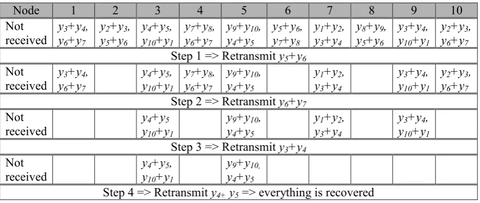
The following example shows how many ARQ requests from each source are required with
the proposed scheme when two packets are not received by each node. In this example, =10.
Table 1 shows which packet combinations were not received. Only one packet is needed out
of the two missing packets for any node to recover all other nodes’ messages. The histogram
of Fig. 4 (a) shows how many of which packets are needed from the relay via ARQ from each
step. At first, packet combinations y3+y4, y5+y6, and y6+y7are most needed. Therefore, we
randomly pick any one of these three; in our example, we retransmit y5+y6. Table 1 now
shows at step 2 which signals are still missing to recover all other nodes’ messages, and a
second packet combination is broadcast after consulting the histogram of Fig. 4 (a). As packet
combinations are progressively re-transmitted, nodes begin to recover all their unknowns –
this is shown as empty cells in Table 1, taking into consideration that the ten nodes can
Table 1: ARQ requests to the relay when any two random packets are not received per source node.
Node 1 2 3 4 5 6 7 8 9 10
Not received
y3+y4, y6+y7
y2+y3, y5+y6
y4+y5, y10+y1
y7+y8, y6+y7
y9+y10, y4+y5
y5+y6, y7+y8
y1+y2, y3+y4
y8+y9, y5+y6
y3+y4, y10+y1
y2+y3, y6+y7
Step 1 => Retransmit y5+y6
Not received
y3+y4, y6+y7
y4+y5, y10+y1
y7+y8, y6+y7
y9+y10, y4+y5
y1+y2, y3+y4
y3+y4, y10+y1
y2+y3, y6+y7
Step 2 => Retransmit y6+y7
Not received
y4+y5 y10+y1
y9+y10, y4+y5
y1+y2, y3+y4
y3+y4, y10+y1
Step 3 => Retransmit y3+y4
Not received
y4+y5, y10+y1
y9+y10, y4+y5
Step 4 => Retransmit y4+ y5 => everything is recovered
Only four ARQ requests are required via cooperation for all nodes to recover the nine
unknown packets instead of every single packet that is not received for all nodes, i.e., ten
packets in this example. This results in a significant 60% savings in ARQ transmissions.
In fact, in the case where any two combined packets are not received by any source node, a
maximum of /2 combined packets is requested to be repeated instead of uncombined
packets when NC is not applied. The minimum number of ARQ packet requests is one, when
one common packet is not received by all nodes, as in Step 4 in Table 1. When three
packets are still not received by Nodes 3 and 5, only the y4+y5 combined packet is needed,
i.e., Node 3 uses y4+y5 to retrieve y10+y1 and Node 5 uses the same combined packet to
retrieve y9+y10.
In Table 2, another example is shown where different nodes do not receive different number
of combined packets and the same process of broadcasting the packets missed by most nodes
is applied until all nodes have received -1 unique packets. We observe that seven packets
are requested to be re-transmitted according to Fig. 4 (b).
Node 1 2 3 4 5 6 7 8 9 10 Not
received
y3+y4, y6+y7, y10+y1
y2+y3, y5+y6, y8+y9, y9+y10
y4+y5, y10+y1
y1+y2, y3+y4, y5+y6, y6+y7, y7+y8
y1+y2, y4+y5, y7+y8
y5+y6, y7+y8
y1+y2, y2+y3
y1+y2, y4+y5, y5+y6, y6+y7, y8+y9, y10+y1
y3+y4, y5+y6, y8+y9, y10+y1
y2+y3, y6+y7, y9+y10
Step 1 => Retransmit y5+y6
Not received
y3+y4, y6+y7, y10+y1
y2+y3, y8+y9, y9+y10
y4+y5, y10+y1
y1+y2, y3+y4, y6+y7, y7+y8
y1+y2, y4+y5, y7+y8
y1+y2, y2+y3
y1+y2, y4+y5, y8+y9, y10+y1
y3+y4, y8+y9, y10+y1
y2+y3, y6+y7, y9+y10
Step 2 => Retransmit y10+y1
Not received
y3+y4, y6+y7
y2+y3, y8+y9, y9+y10
y1+y2, y3+y4, y6+y7, y7+y8
y1+y2, y4+y5, y7+y8
y1 +y2, y2+y3
y1+y2, y4+y5, y8+y9
y3+y4, y8+y9
y2+y3, y6+y7, y9+y10
Step 3 => Retransmit y1+y2
Not received
y3+y4, y6+y7
y2+y3, y8+y9, y9+y10
y3+y4, y6+y7, y7+y8
y4+y5, y7+y8
y4+y5, y8+y9
y3+y4, y8+y9
y2+y3, y6+y7, y9+y10
Step 4 => Retransmit y6+y7
Not received
y2+y3, y8+y9, y9+y10
y3+y4, y7+y8
y4+y5, y7+y8
y4+y5, y8+y9
y3+y4, y8+y9
y2+y3, y9+y10
Step 5 => Retransmit y8+y9
Not received
y2+y3, y9+y10
y3+y4, y7+y8
y4+y5, y7+y8
y2+y3, y9+y10
Step 6 => Retransmit y2+y3
Not received
y3+y4, y7+y8
y4+y5, y7+y8
0 0.5 1 1.5 2 2.5 3
1+2 2+3 3+4 4+5 5+6 6+7 7+8 8+9 9+10 10+1
N
u
m
b
e
r
re
q
u
ir
e
d
Packet combination
Step 1 Step 2 Step 3 Step 4
0 1 2 3 4 5
1+2 2+3 3+4 4+5 5+6 6+7 7+8 8+9 9+10 10+1
N
u
m
b
e
r
re
q
u
ir
e
d
Packet combination
Step 1 Step 2 Step 3 Step 4 Step 5 Step 6 Step 7
Fig. 4: Number of packets required for each packet combination missing (a) two (b) more than two
packets
In the second example with a worse scenario, only seven combined packets are retransmitted
instead of N=10 packets, still resulting in a significant 30% savings in ARQ transmissions.
Therefore, through a simple process (at the relay) of counting ARQ requests from all nodes in
the network, it is possible to achieve significant savings in retransmissions via cooperative
network coding.
5. HIGH-SR BEHAVIOUR
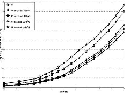
Fig. 5 shows the AFb, DFb/DFp and AFp capacities from (4), (5), and (7), respectively vs.
SNR in the uplink for two different values of A=AAFb=AAFp=ADFb=ADFp. All four schemes
use the same total transmitter power. Since the capacities of both benchmark and proposed (a)
DF schemes are identical, they are shown as a single DF curve. It can be seen that DF
provides performance gain over AF, which decreases with A.
-10 -8 -6 -4 -2 0 2 4 6 8 10
0 0.2 0.4 0.6 0.8 1 1.2 1.4 1.6 1.8
SNR[dB]
C
a
p
a
c
it
y
[
b
it
s
/c
h
a
n
n
e
l
u
s
e
]
DF
[image:19.595.96.528.125.449.2]AF benchmark AFb2=9 AF benchmark AFb2=3 AF proposed AFp2=9 AF proposed AFp2=3
Fig. 5: The capacities of the four systems as functions of the SNR in the uplink channel
By comparing dashed and solid lines in Fig 5, it can be seen that the gain of DF over AF is
less when A is higher, as expected from (5) and (7). On the other hand, the increase in A
enlarges the performance gap between the proposed AF schemes and the benchmark AF.
Another conclusion from the figures is that, in theory, NC does not provide any capacity
improvement when AF is used. This is due to the accumulation of the noises over three
separate paths. On the other hand, without NC, each coded message travels via two
transmission paths, and thus encounters two independent noisy channels only. However, NC
provides savings in the number of transmissions needed.
Two parameters are usually used to measure system performance in the high SNR regime:
multiplexing gain shows how fast the capacity increases with SNR. It is defined
by
SR SR C
r SR
log 2 1
) ( lim →∞
= , where C is the capacity.
All four schemes behave similarly in the high SNR regime achieving rate multiplexing gain
of one (which is expected since all the systems use a single transmitter antenna). This can be
observed from Fig. 5, as all four curves become parallel.
Additive gain is defined as
SR r SR
C
a SR
log 2 ) (
lim −
= →∞ . It is a shift of the
) (SR
C function from the origin at high SNRs. The DF schemes achieve a=0, whereas the
benchmark, and the proposed AF cooperative protocol schemes achieve
1 log
2 2
+ =
AFb AFb
A A
a ,
and
1 2
log 2
2
+ =
AFp AFp
A A
a , respectively. Hence the DF schemes achieve higher additive gain.
6. SIMULATIO RESULTS
We use Partial Unit Memory Turbo codes (PUMTC) introduced in [9] and showing capacity
approaching performance via EXIT charts in [10]. In our systems, transmission is simulated
over AWGN, using BPSK modulation for rate 1/3 PUMTCs based on (8,4,3,8) and (4,2,1,4)
PUM component codes, and a pseudo-random interleaver of size 1000 bits. The (8,4,3,8)
PUMTC is more robust, but more complex than the (4,2,1,4) PUMTC. We
set = = = =4
DFb A DFp A AFb A AFp
A , and four decoding iterations for the simulation
run. The BER performance curves are obtained by simulating transmission of at least 108 bits
-1 0 1 2 3 4 5 6 7 10-8
10-7 10-6 10-5 10-4 10-3 10-2 10-1 100
SNR (dB)
B
it
E
rr
o
r
R
a
te
(
B
E
R
)
AFb (4,2,1,4) DFb (4,2,1,4) AFb (8,4,3,8) DFb (8,4,3,8)
AFp Two-Source (4,2,1,4) DFp Two-Source (4,2,1,4)
[image:21.595.83.521.70.370.2]AFp Two-Source (8,4,3,8) DFp Two-Source (8,4,3,8)
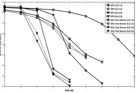
Fig. 6: BER for the AF and DF systems based on (8,4,3,8) and (4,2,1,4) PUMTC for N=2.
Fig. 6 compares the proposed and benchmark AF and DF systems for both PUMTCs. As
expected the (8,4,3,8) PUMTC outperforms the (4,2,1,4) PUMTC, and the DF systems
outperform the AF systems which are less delay-prone but are noisier. The performance
improvement of DF over AF is significantly larger for the (8,4,3,8) PUMTC over the
(4,2,1,4) PUMTC, demonstrating the effect in choosing a good channel code. In addition,
there is a significant BER performance loss for AFp compared to AFb, which is the trade-off
in terms of bandwidth savings. On the other hand, the DFp performance is only marginally
worse than the DFb system, which makes it a better option when performance is more critical
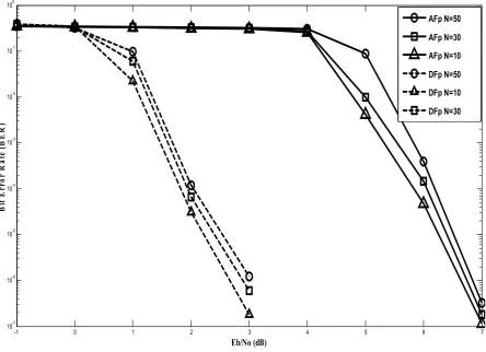
and latency is less so. Fig. 7 shows the effect of increasing the number of nodes from 10 to
50 in the network for both proposed AF and DF systems. As expected, with no additional
DFp, respectively is observed with increasing number of nodes while maintaining only -1
DL transmissions.
-1 0 1 2 3 4 5 6 7
10-7
10-6
10-5
10-4
10-3
10-2
10-1
100
B
it
E
rr
o
r
R
a
te
(
B
E
R
)
Eb/o (dB)
AFp N=50
AFp N=30
AFp N=10
DFp N=50
DFp N=10
[image:22.595.78.523.139.461.2]DFp N=30
Fig. 7: AFp and DFp systems based on (8,4,3,8) PUMTC for N=10, 30 and 50.
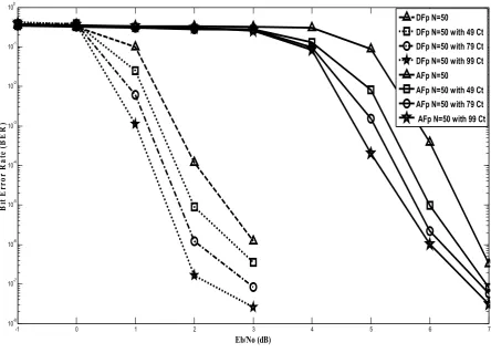
Fig. 8 demonstrates the influence of increasing the number transmitted packets over AF and
DF, showing that sending 99 additional packets (almost double the number of source nodes)
to aid in the message recovery process in AF results in a 1.2 dB gain and 1.4 dB in the DF
-1 0 1 2 3 4 5 6 7 10-8
10-7 10-6 10-5 10-4 10-3 10-2 10-1 100
Eb/o (dB)
B
it
E
rr
o
r
R
a
te
(
B
E
R
)
[image:23.595.77.522.70.389.2]DFp N=50 DFp N=50 with 49 Ct DFp N=50 with 79 Ct DFp N=50 with 99 Ct AFp N=50 AFp N=50 with 49 Ct AFp N=50 with 79 Ct AFp N=50 with 99 Ct
Fig. 8: AFp and DFp systems based on (8,4,3,8) PUMTC, demonstrating the effect of adding up to 99
additional packets.
7 COCLUSIO
This paper considers a low-complexity physical layer network encoding and decoding
scheme for bandwidth- and power- savings for an information exchange scenario via a relay
with Amplify-and-Forward (AF) or Decode-and-Forward (DF) based schemes. The systems
combine network coding with high-performance partial-unit memory-based turbo codes for
forward error correction. The theoretical limits of capacity for the proposed schemes are
shown with the schemes’ behaviour in high and low SNR regimes. The paper proposes a
deterministic combination scheme where messages from two nodes are combined by the relay
before broadcasting by AF or DF, yielding a savings in 1/ in transmissions. A modified
version of the Gauss-Jordan elimination algorithm is proposed for message recovery
decrease the effect of error propagation inherent in the recovery process. Simulation results
for all proposed schemes demonstrate their relative performance over the benchmark scheme,
and are promising due to their performance and simplicity.
Additionally, we propose a cooperative network coding scheme to reduce transmissions of
ARQ packets when source nodes across the network do not receive packets. Again, we show
that when the relay broadcasts most requested combinations in a step-by-step fashion, it is
possible to achieve significant savings in transmissions over traditional (benchmark without
REFERECES
[1] Glats, P., Hein, K., and Weiss, R.: ‘Energy Conservation with Network Coding For Wireless Sensor Networks with Multiple Crossed Information Flows,’ Proc. 10th International Symposium on Pervasive, Algorithms, and Network, Taiwan, December, 2009, pp 201-207. [2] Liang, X., Chen, M., Xiao, Y., Balasingham, I., and Leung, V.: ‘A Novel Cooperative Communication Protocol for QoS Provisioning in Wireless Sensor Network,’ Proc. 5th Int. Conf. on Testbeds and Research Infrastructures for the Development of Networks & Communities and Workshops,, Washington, April, 2009.
[3] Stankovic, V., Host-Madsen, A., Xiong, Z.: ‘Cooperative diversity for wireless ad hoc networks: capacity bounds and code designs,’ IEEE Signal Processing Magazine, 2006, 22, pp. 37-49.
[4] Woldegebreal, D., and Karl, H.: ‘Network-coding-Based Cooperative Transmission in Wireless Sensor Networks: Diversity-Multiplexing Tradeoff and Coverage Area Extension’
Springer- Verlag Berlin, 2008, 4913, pp. 141-155.
[5] Jayaweera, S.: ‘Virtual MIMO-based cooperative communication for energy-constrained wireless sensor networks,’ IEEE Trans. Wireless Commun., 2006, (5), pp. 984-989.
[6] Jayaweera, S.: ‘Energy Analysis of MIMO Techniques in Wireless Sensor Networks,’ Proc. 38th Annual Conf. on Information Sciences and Systems (CISS 04), Princeton, NJ, March, 2004.
[7] Ahlswede, R., Cai, N., Li, S-Y., and W. Yeung, R.: ‘Network information flow,’ IEEE Trans. Inform. Theory, 2000, 46, pp. 1204-1216.
[8] Stankovic, V., Fagoonee, L., Moinian, A., and Cheng, S.: ‘Wireless Full-duplex Communication Based on Network Coding,’ Forty-Fifth Annual Allerton Conference, Illinois, USA, 2007.
[9] Fagoonee, L., and Honary, B.: ‘Construction of partial unit memory encoders for application in capacity-approaching concatenated codes,’ IEE Proc. Comm.: Special Issue on Capacity Approaching Codes, Design and Implementation, 2005, 152, (6), pp. 1108-1115. [10] Nelson, C., Stankovic, L., and Honary, B.: ‘Partial-Unit Memory based Turbo Codes,’ IET Electronics Letters, 2009, 45, (21).
[11] Hausl, C., Schreckenbach, F., Oikonomidis, I., and Bauch, G.: ‘Iterative network and channel decoding on a Tanner graph,’ Proc. Allerton, Monticello, IL, Sept. 2004.
[12] Hausl, C., and Hagenauer, J.: ‘Iterative network and channel decoding for the two-way relay channel,’ Proc. IEEE ICC, Istanbul, Turkey, June 2006.
[13] Xiao, L., Fuja, T.E., Kliwer, j., and Costello, D.J.: ‘Nested Codes with Multiple Interpretations,’ Proc. CISS, Princeton, USA, March, 2006.
[14] Popovski, P., and Yomo, H.: ‘The Ant-Packets Can Increase the Achievable Throughput of a Wireless Multi-Hop Network,’ Proc. IEEE ICC, Istanbul, Turkey, June 2006.
[15] Popovski P., and Yomo H., ‘Bi-directional amplification of throughput in a wireless multi-hope network,’ in Proc. IEEE 63rd VTC, Melbourne, Australia, May 2006.
[16] H. Gacanin and F. Adachi, "Broadband analog network coding," IEEE Trans. on Wireless Communications, Vol. 9, No. 5, pp. 1577-1583, May 2010.
[17] Jianquan L, Meixia T, Youyun X, and Xiaodong W., ‘Superimposed XOR: ‘A New Physical Layer Network Coding Scheme for Two-Way Relay Channels’ . IEEE Communications Society subject matter experts for publication in the IEEE "GLOBECOM" proceedings, 2009
[19] El Gamal A., Mohseni M., and Zahedi S., ‘Bounds on Capacity and Minimum Energy-Per-Bit for AWGN Relay Channels Fellow’, IEEE Tras. On Information Theory, Vol. 52, No. 4, April 2006