CPD ANALYSIS OF HEAT SOURCE FROM ELECTRRIC VEHICLE BATTERY
SYSTEM
MUHAMMAD ZIKRILLAH BIN YUNUS
CFD ANALYSIS OF HEAT SOURCE FROM ELECTRRIC VEHICLE BATTERY SYSTEM
MUHAMMAD ZIKRILLAH BIN YUNUS
This report is submitted in accordance with requirement for the Bachelor of Mechanical Engineering (Automotive)
Faculty of Mechanical Engineering Universiti Teknikal Malaysia Melaka
SUPERVISOR DECLARATION
"I admit that had read this thesis and in my opinion this thesis was satisfied from the aspect of scope and quality for the purpose to be awarded Bachelor of Mechanical
Engineering (Automotive)"
Signature
Name of Supervisor Date
DECLARATION
"I verify that this report is my own work except for the citation and quotation that the source has been clarified for each one of them"
Signature Name of Author Date
:
...
~
....
~
... .
DEDICATION
To my parents, Yunus Bin Yussof and Sina @Hasinah Bte Alwe, my siblings, my
friends and my supervisor, Dr. Noreffendy bin Tamaldin, for supporting me
throughout this project and for their understanding in the way I am.
ACKNOWLEDGEMENT
Alhamdulilah, I would like to thank Allah for providing me strengths to
accomplish this Project Sarjana Muda. My heartiest thanks to whom who had helped
and guided me throughout my study period in Universiti Teknikal Malaysia Melaka.
I would like to express my gratitude to my supervisor, Dr. Noreffendy Bin
Tamaldin, who is willing to offer his support throughout my final year project. He
has graciously contributed his time, patience, and guidance in helping me
completing my project. Without him, I would never achieve what I have meant to
complete. His constant encouragement and guidance had brought me to the final
stage of my project.
I also would like to forward my thanks to my father, Yunus Bin Yussof, who
had been supporting the financial to complete this project. Thanks also to my mother,
Sina@hasinah Bte Alwi who always gave words of encourage my spirit so that I can
keep my momentum in obtaining achievement.
Finally, I would like to thanks to all my friends who help and guide me
discussed about my project. Without their sharing idea, I can't finish this project.
ABSTRACT
Battery is one of a very important element for electric vehicle. Battery
thermal management should be emphasized to ensure the use of extended batteries
and to avoid the catastrophic destruction .To identify the behaviour of the heat flow
that occur on the battery, analysis of thermal convection flow had been made along
the heat sink at batteries . Convection is a mode of heat transfer which includes the
movement of the molecules of the material. The fluid motion enhance the heat
transfer, since it brings wanner and cooler chunks of fluid into contact, initiating
higher rates of conduction at a greater number of sites in a fluid. The application
software of Computational Fluid Dynamic (CFD) had been used to show the
graphical heat distribution along the flow of air that passes the battery duct. In
addition, this study also examines the relationship between vehicle speeds with the
rate of heat transfer by using existing data. The result shows the changes of heat for
air from inlet to outlet flow for the heat sink batteries. The value of heat transfer is
positive means that the heat from the batteries had distributes along the air flow. To
find out whether computerized analysis is wrong or not, confirmation had been made
by comparing the data with the data from theoretical calculation. Validation results
show only slight differences between the data of both analysis and can be assuming
that the analysis is valid.
ABSTRAK
Bateri adalah salah satu elemen yang sangat penting untuk kenderaan elektrik.
Pengurusan haba bateri perlu diberi penekanan bagi memastikan jangka hayat bateri
yang panjang dan untuk mengelakkan kemusnahan yang teruk. Untuk mengenal pasti
tingkah laku aliran haba yang berlaku pada bateri, analisis aliran perolakan haba
telah dibuat bersama-sama alatan pengurang haba pada bateri. Perolakan adalah mod
pemindahan haba melalui pergerakan molekul bahan. Gerakan cecair meningkatkan
pemindahan haba, kerana ia membawa ketulan panas dan sejuk cecair kepada
sentuhan permukaan , memulakan kadar pengaliran yang lebih tinggi pada nilai yang
lebih besar daripada tapak dalam cecair.Perisian "Computational Fluid Dynamic
(CFD)" telah digunakan untuk menunjukkan pengagihan haba grafik bersama-sama
aliran udara yang melalui salur bateri. Di samping itu, kajian ini juga mengkaji
hubungan antara kelajuan kenderaan dengan kadar pemindahan haba dengan
menggunakan data yang sedia ada. Hasil menunjukkan bahawa perubahan haba bagi
udara dari masukan ke keluaran aliran saluran untuk bateri di kawasan penyejukan
haba. Nilai pemindahan haba menunjukkan nilai positif bermaksud haba dari bateri
telah dipindahkan pada aliran udara yang melaui kawasan penyejukan haba. Untuk
mengetahui samaada analisis berkomputer tersebut berlaku kesilapan atau tidak,
pengesahan telah dibuat dengan membandingkan data dengan data daripada
pengiraan teori. Keputusan pengesahan menunjukkan hanya sedikit perbezaan antara
TABLE OF CONTENTS
CHAPTER TITLE
DECLARATION
DEDICATION
ACKNOWLEDGEMENT
ABSTRACT
ABSTRAK
LIST OFT ABLES
LIST OF FIGURES
LIST OF SYMBOL
LIST OF APPENDICES
1.0 INTRODUCTION
I. I Overview
I .2 Objectives
I.3 Scopes
I .4 Problem Statement
2.0 LITERATURE REVIEW
2.I Electrical Vehicle
2. I. I Heat management System
2.2 Battery
2.2. I Lithium-ion Battery
CHAPTER TITLE
PAGE
2.2.2 Battery Efficiency 7
2.3 Heat Transfer 8
2.3.l Conduction 8
2.3.2 Convection 9
2.3.2.1 Renault Number 9
2.3.2.2 Nusselt Number 10
2.3.2.3Pradtl Number 11
2.4 Other compartment of Battery 12
2.5 Heat Sink 12
2.5.1 Material Selection 13
2.5.2 Aluminium Alloy 13
3.0
METHODOLOGY
3.1 Research Methodology 14
3.2 Collecting Data 15
3.3 Assumption 17
3.4 Parameter 18
3.4.1 Average Velocity and Temperature 18
CHAPTER TITLE
3.4.5 Heat Transfer
3.5 Computational Fluid Dynamic
3.5.1 Generate Geometry
3.5.2 Mesh
3.5.3 Boundary Condition
3.5.4 Type of Material
4.0 RESULT AND DISCUSSION
4.1 Result
4.2 Validation
4.2.1 Calculation on Behaviour of Air
4.2.2 Data Differences
4.2.2.1 Percentage of Error
4.3 Design Recommendation
5.0 CONCLUSION AND RECOMMENDATION
5.1 Conclusion
5 .2 Recommendation
LIST OFT ABLES
NO TITLE PAGES
2.1 Combination of electrolyte and the volt result electrode 5
2.2 Typical range of Prandtl numbers for common fluids 11
3.1 Selected variation data of speed, velocities inlet and 17
batteries temperature from Evergreen vehicle
4.1 Tabulation of Theoretical Data and Experimental Data 34
4.2 Summary for improvement of heat management on 37
LIST OF FIGURES
NO TITLE PAGES
2.1 'Smart fortwo' first fully electrical vehicle 4
2.2 Electrode flow from the zinc to cooper electrode 6
2.3 Performance discharge of the volts with different 7
temperature
2.4 Process of heat transfer 8
2.5 Compartment of battery 11
3.1 Flow process of methodology 14
3.2 Exploded view of battery part 16
3.3 Base of the battery isometric detail drawing 16
3.4 Hydraulic diameter for rectangular duct 19
3.5 Battery pack 22
3.6 Heat sink Pack 22
3.7 Single heat sink 22
3.8 Pack of air inside the duct 22
3.9 Meshing of air geometry 24
3.10 Parameter of wall boundary condition 25
3.11 Boundary Condition of the inlet and outlet 25
3.12 Parameter of inlet boundary condition 26
4.1 Relative Total Temperature of Air for Vehicle Speed at 28
20km/h
4.2 Relative Total Temperature of Air for Vehicle Speed at 28 40km/h
4.3 Relative Total Temperature of Air for Vehicle Speed at 29
60km/h
4.4 Relative Total Temperature of Air for Vehicle Speed at 29
80km/h
4.5 Relative Total Temperature of Air for Vehicle Speed at 30
lOOkm/h
4.6 Heat Loss from the Duct of a Battery 31
4.7 Graph of Temperature Exit against Vehicle Speed 35
4.8 Graph of Rate of Heat Loss against Vehicle Speed 36
4.9 Current Design of the Duct in Heat Sink 38
LIST OF SYMBOL
SYMBOL
Re
Renault Numberp Density
v Kinematic viscosity
v
Upstream velocityNu Nusselt Number
h Heat transfer coefficient
k Thermal Conductivity
Pr
Pradtl Numbera Molecular difussivity of heat
Q Heat transfer
As Surface area
Ts Temperature surface
Too Ambient temperature
Vavg Average flow velocity
Dh Hydraulic diameter
f
Smooth tubeTe Exit temperature
Ti Inlet temperature
m.
Mass flow rateCp Specific heat
APPENDIX A
APPENDIXB
APPENDIXC
LIST OF APPENDICES
xv
Flow Chart Project
Battery Diagram
CHAPTERl
INTRODUCTION
1.1 Overview
Now a day, the development of electric vehicle is growing rapidly. Many
automotive industries explore feasibility study about this kind of vehicle such as
Hyundai and Toyota. The electric vehicles getting popular since the awareness of the
emission and reduction amount of fuel become the hot issues. There are several
factors that need to be considered in producing a good quality of the electric vehicle.
Some limitation exists and need to be addressed by the research division in the
company. One of importance causes that need to be concern is optllnizing the crucial
part of electric car that is a battery. Ahmad A.P, (2001 ), states that the battery
performance, life and cost directly affect the performance, life, a cost of the electric
1.2 Objectives
The objective of this project is to characterize the heat transfer behaviour of
component in electrical vehicle that is battery system. Besides that, it was intended to
study the efficiencies of heat transfer rate in battery parts at different vehicle speed.
1.3 Scopes
The scopes of this project are to study the temperature profile of electric
vehicle battery and study about the effect of speed to the efficiencies of heat transfer.
Next, is to perform Computational Fluid Dynamic (CFD) analysis and also to
provide the recommendation for improvement of cooling system for battery.
1.4 Problem Statement
At UTeM, the existing electric vehicle named as Evergreen had participate
the competition of Proton Green Mobility Challenge and this become the starting
point for serious development for this kind of vehicle in Faculty of Mechanical
Engineering and Faculty of Electrical Engineering. They are lot of factor and
analysis that need to be done in order to perform improvement. One of key factor is
about the heat management in the vehicle. The heat management system played as a
main role to optimize the safety and the durability of the vehicle. In order to identify
the problem that may occur in current heat management system, the behaviour of
heat transfer for battery needed to be known by doing some analyzation. The result
of the analysis will be use to provide recommendation for future study.
CHAPTER2
LITERATURE REVIEW
2.1 Electrical Vehicle
Electrical vehicle is one of the green technologies where the rotation or
movement of the vehicle tyre propelled by the electric motor and powered by electric
storage. The integration of electric motor, controller and battery produce the
complete main element for the electric vehicle with additional of other transmission
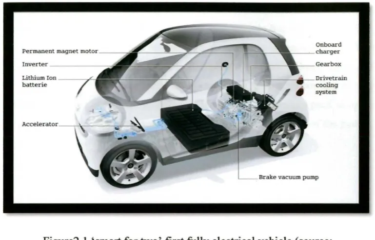
and accessories part. Figure 2.1 shows one of the first fully electric vehicles
Onboard charger
Gearbox
...----~Drivetrain
cooling
system
Brake vacuum pump
Figure2.l 'smart for two' first fully electrical vehicle (source: http://www.globalgiants.com)
Originally, Sent Leitman, (2008), says the usage of electric motor type vehicle started develop since a long time ago around 1835 that introduced by Thomas Davenport. Until late of the 19th century the development still occurred but the progression process still considered slow. He also state that, by 20th century, the awareness about the emission and the reduction of the fossil fuel become the big issues and lot of car maker and company such as General Motor, Honda, Nissan and Toyota try to implement the electric vehicle in their own production. Since that time,
the rapid research and development of electric vehicle occurred to the automotive industry all over the world.
2.1.1 Heat Management System
Heat management system or thermal management for electric vehicle is different with the internal combustion Engine (ICE). In electric vehicle the heat source generated from the electronic devices and the circuit such as the motor electric and the controller differ to the conventional car( internal combustion engine)
[image:21.524.73.458.46.293.2]the heat source come from the engine during the burning stroke. Usually the heat
generation for electric vehicle not hot as the ICE vehicle but the electrical devices
and the circuit is very sensitive to the high temperature. Commonly, the thermal
management system in electric vehicle focus on the most valuable and critical
components that are the power supplier or known as battery. According to Ahmad
A.P, (2001), the goal of thermal management is to deliver a battery pack at optimum
average temperature. This is because the temperatures effect the life of the battery.
2.2Battery
The purpose of battery is just same as the generator or alternator means that
to supplies power but in small portion. The existing of the battery enables human
being to use the other portable or small devices such as cell phone, flashlight and
calculator. In automotive field, usually the batteries use for the starter and now the
usage of battery getting essential as the power supplier for a electrical vehicle. In
fabrication of battery involve of anode and cathode as electrode and electrolyte. The
type of electrode and electrolyte can be different depends on it purpose .Each unique
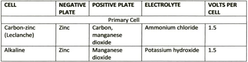
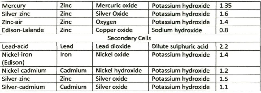
combination can provide different value of voltage ,Stephen (L.Herman,2011).The
Table 2.1 shows example of electrolyte and electrode combination and the volt result
while the Figure 2.2 shows the common structure of battery.
Table 2.1 Combination of Electrode and Electrolyte and the Volt result electrode
(source from (Stephen L.Herman, 2011))
CELL NEGATIVE POSITIVE PLATE ELECTROLYTE VOLTS PER
[image:22.524.47.475.596.703.2]Mercury Zinc Mercuric oxide Potassium hydroxide 1.35
Silver-zinc Zinc Silver Oxide Potassium hydroxide 1.6
Zinc-air Zinc Oxygen Potassium hydroxide 1.4
Edison-Lalande Zinc Copper oxide Sodium hydroxide 0.8
Secondary Cells
Lead-acid Lead Lead dioxide Dilute sulphuric acid 2.2
Nickel-iron Iron Nickel oxide Potassium hydroxide 1.4
(Edison)
Nickel-cadmium Cadmium Nickel hydroxide Potassium hydroxide 1.2
Silver-zinc Zinc Silver oxide Potassium hydroxide 1.5
[image:23.524.57.479.46.197.2]Silver-cadmium Cadmium Silver oxide Potassium hydroxide 1.1
Figure 2.2 Electrode flow from the zinc to cooper electrode (source from (Stephen L.Herman, 2011))
2.2.1 Lithium-ion Battery
Lithium-ion cells a very popular for portable equipment such as net book,
video camera, cell phone. This cell is choosing due to the capability of the cell to recharge and offer very high energy density for their size and weight. They exhibit a voltage of 3.6 volts per cell, which is the same voltage that can be obtained by connecting three nickel-cadmium or three nickel metal hydride cells in series. Under
proper charging condition these cell can be recharge about 500 times. Moreover, this
cell also has no problem with memory accumulation means that they can be
recharged to their full capacity each time they charged (Stephen L.Herman, 2011 ).
Other than that this cell also can safely be recharged because they do not contain
metallic Lithium.
2.2.2 Battery Efficiency
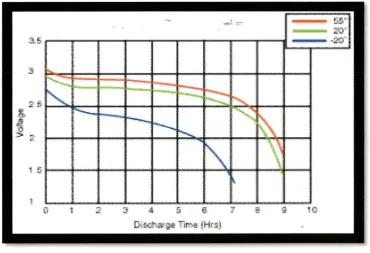
In the electrical vehicle, temperature played a main role to giving batter
[image:24.524.81.452.319.572.2]performance and the durability of the battery.
Figure 2.3: Performance discharge of the volts with different temperature (source