International Journal of Innovative Technology and Exploring Engineering (IJITEE) ISSN: 2278-3075,Volume-8 Issue-12, October 2019
Abstract: The offshore jacket platforms are primarily installed in the large oceans mainly for drilling the crude oil, carbohydrates and production of electricity. The current studies emphasize on the structural performance of offshore deck jacket platform with different bracing systems. Earthquake analysis has been performed to calculate the seismic responses, with the help of bracings to control the seismic induced vibrations of the jacket platforms. For this study, a jacket platform made up of steel members has been modeled and then analyzed under earthquake and wave loadings. This paper mainly deals to compute and compare the seismic behavior of offshore steel deck platform using SAP 2000 v20 software with bracing in the horizontal plane and bracing in both horizontal and vertical planes. The total number of 8 models has been analyzed in the SAP2000 software with bracing i.e. X, V, Inverted V and K in the vertical plane and bracing i.e. X, V, Inverted V and K in both horizontal and vertical plane.A relative study has been carried out in Time period, deck displacement and base shear. Seismic analysis using linear static, i.e. Equivalent static method (ESA) and linear dynamic, i.e. Response spectrum method (RSA) has been performed. Further deck displacement, time period and base shear are determined by Equivalent static method and Response spectrum method for various types of bracing models in both horizontal and vertical planes. Among the all various types of bracing models, Inverted V bracing in the vertical plane is found to be the optimum model among all other models.
Keywords:Offshore Steel Jacket Platform, Base Shear, Time period, ESA, RSA, SAP2000 v20 software.
I. INTRODUCTION
Offshore structure is the installation and construction of jacket platforms in the oceans and seas, mainly for the production and transmission of electricity, oil, gas and other resources. In order to make a reliable design of a platform, it is important to evaluate an exact seismic response. The offshore platforms are subject to various environmental loading during their lifetime. These loads are enforced on the deck platform through natural process such as wind, wave, current, earthquake, snow, ice and earth movements. There are nearby more than 9000 oil and gas offshore deck platforms around the world for drilling oil and gas in the need of hydrocarbons from the oil regions. The overall amount of
Revised Manuscript Received on October 05, 2019.
Md. Yousuf Ahmed PG Student, Department of Civil Engineering, PDA
College of Engineering Kalaburgi-585102, Karnataka, India. Email: [email protected]
Dr. Aravind Kumar Harwalkar Associate Professor Department of
Civil Engineering, PDA College of Engineering Kalaburgi-585102, Karnataka, India.
Email: [email protected]
offshore deck platforms in different bays, gulf and oceans of the world are growing day by day, most of them are of fixed type. Seismic forces must be considered in the design of offshore jacket deck platform for the regions that are called to be seismically active. In order to govern seismic excitation numerous methods are used such as dampers. In this work, it is an attempt to explore the effect of offshore jacket deck platform with bracing in the vertical plane and bracing in both horizontal & vertical planes. Here it is mainly highlighted on static and dynamic analysis of offshore jacket deck platform. Recently, many of the research scholars have worked on the offshore deck structure. Sreelakshmi and Jayalekshmi [1] carried out the studies on response of offshore deck platforms installed with a passive energy dissipation device i.e., friction dampers and they found that friction dampers helps in decreasing deck displacement of the platform up to 65%. Nonlinear analysis of a jacket deck platform under simultaneously wave and earthquake loading have been conducted in the literature [2] and the results showed that the displacement of the deck structure under combination of two loads (earthquake and wave loads) are more than the displacement of earthquake load alone. The studies carried out on grouping of MR dampers and a friction pendulum at the junctions of the cellar deck in order to control earthquake vibrations under Kobe seismic excitation was conducted by Taghikhany T et al [3]. The results showed that MR dampers efficiently help in reducing displacement & acceleration. From the results of time history analysis of the deck platform with Semi Active Tuned Damper reported in the literature [4] showed that Semi Active Tuned Damper can dramatically reduce the acceleration and displacement of the platform. The nonlinear response of a fixed deck platform has been studied under wave loading [5] and it was found that it is crucial to decrease the overall response of an offshore structure subjected to environment loads. The dynamic behaviour of the deck platform for individual and combined wind and wave forces was evaluated [6] and it was found that the maximum deflection is due to combined wind and wave forces when compared to individual force. In the literature [7] the ultimate strength of the fixed jacket platform is analyzed considering the different bracing patterns. The strength of brace-Y is significantly effective when compared to X, K and N bracing. The non-linear pushover analysis of offshore deck structure with different bracing systems considering soil- structure interaction have been studied by S. Ishwarya and R. Senthil [8] and it was found that the type of bracing does not play important part in the seismic
analysis of an offshore platform
Seismic Behaviour of Offshore Steel Jacket
Platform Braced in Horizontal and Vertical
Planes
II. OBJECTIVES OF STUDY
In the current study, it is aimed to determine the behaviour of offshore deck platform subjected to seismic loading. Following are the objectives of the current study:
1. To determine seismic parameters such as base shear, deck displacement and fundamental time period of jacket platform under seismic loading.
2. To study the effect of X, V, Inverted V and K bracing provided in vertical plane on seismic behavior.
3. To compare the effect of bracing in the vertical plane and bracing in both horizontal & vertical plane.
4. To determine the optimum bracing pattern for deck platform from the analysis results of different models.
III. METHODOLOGY
It is an effort to examine the outcome of different bracing patterns for offshore steel deck platform. This thesis generally underscores on analysis of an offshore deck platform by using bracing in the horizontal plane & bracing in both horizontal and vertical plane. The modeling of jacket deck platform structure has been done on the SAP2000 v20 software for Equivalent Static Analysis & Response Spectrum Analysis. The results of SAP2000 software are validated with the results of the literature [1]. After analysis of the jacket deck structure the parameters such as deck displacement, base shear and time period are calculated and then the results are compared for all the analyzed cases.
In the current study, following eight models are considered for the analysis:
1. Jacket deck platform model with X bracing in the vertical plane.
2. Jacket deck platform model with V bracing in the vertical plane.
3. Jacket deck platform model with inverted V bracing in the vertical plane.
4. Jacket deck platform model with K bracing in the vertical plane.
5. Jacket deck platform model with X bracing in vertical plane & bracing in the horizontal plane.
6. Jacket deck platform model with V bracing in vertical plane & bracing in the horizontal plane.
7. Jacket deck platform model with inverted V bracing in vertical plane & bracing in the horizontal plane. 8. Jacket deck platform model with K bracing in vertical
plane & bracing in the horizontal plane. IV. ANALYTICAL MODELLING
A. Offshore Jacket Platform Details
The detail properties of offshore jacket deck platform and the properties of wave loading determined from the API-RP2A [9] used for the analysis are listed in Table- I.
Table- I: Offshore deck platform details
Type of platform Steel Jacket Platform
Type of frame Moment Resisting Frame
No of legs 6 Bottom
Dimension 25m X 15m
Top Dimension 16m X 12m
Size of main deck 24m X 20m
Total height of
platform 90m
Depth of water 70m
Live Load 20KN/m2
Concrete grade M30
Reinforcing steel
grade Fe345
Vertical legs Diameter 1.5m, thickness 0.2m
Horizontal bracing
Diameter 1.25m, thickness 0.15m
Diagonal bracing
Diameter 1.25m, thickness 0.15m
Thickness of slab 250mm
Zone III
Type of soil II
Importance factor 1
Response reduction 5
Seismic zone factor 0.16 for zone III
Wave height 14.86m
Wave time period 21.66Sec
B. Description of the models
International Journal of Innovative Technology and Exploring Engineering (IJITEE) ISSN: 2278-3075,Volume-8 Issue-12, October 2019
Table- II: Description of the models Model
No
Description
1 Jacket deck platform model with X bracing in the vertical plane.
2 Jacket deck platform model with V bracing in the vertical plane.
3 Jacket deck platform model with inverted V bracing in the vertical plane.
4 Jacket deck platform model with K bracing in the vertical plane.
5 Jacket deck platform model with X bracing in vertical plane & bracing in the horizontal plane.
6 Jacket deck platform model with V bracing in vertical plane & bracing in the horizontal plane.
7 Jacket deck platform model with inverted V bracing in vertical plane & bracing in the horizontal plane.
8 Jacket deck platform model with K bracing in vertical plane & bracing in the horizontal plane.
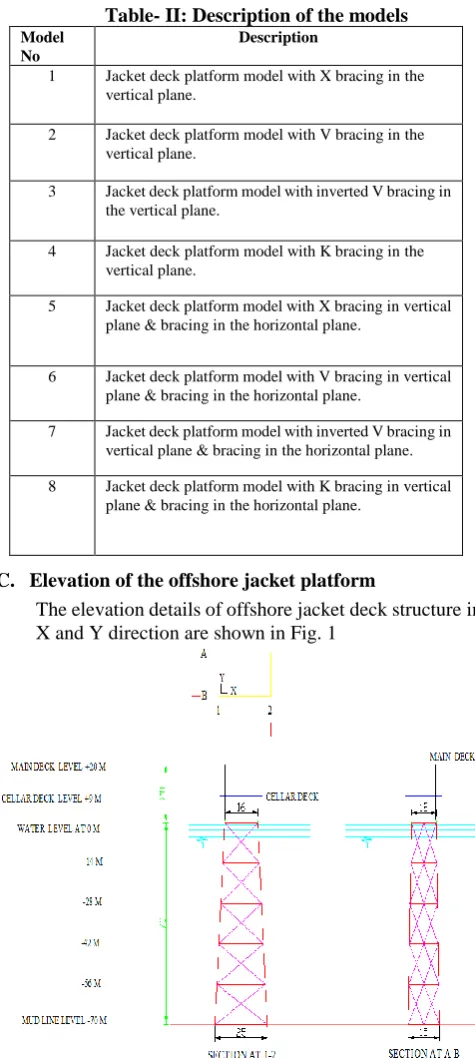
C. Elevation of the offshore jacket platform
The elevation details of offshore jacket deck structure in X and Y direction are shown in Fig. 1
Fig.1. Elevation of the offshore jacket deck platform
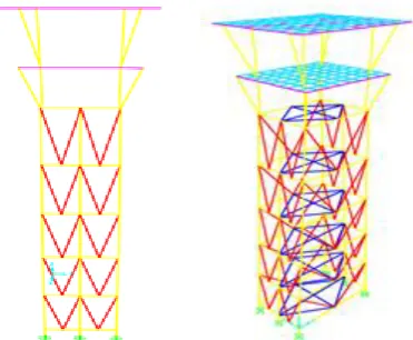
D. Modelling of different models in SAP2000 Software The different bracing models used for the deck platform in the current study are shown in Fig.2 to Fig. 9.
[image:3.595.49.287.49.579.2][image:3.595.322.513.52.215.2]
Fig.2. X bracing in vertical plane
Fig. 3. V bracing in vertical plane
[image:3.595.49.292.369.584.2]Fig. 5. K bracing in vertical plane
[image:4.595.57.242.55.414.2]
Fig. 6. X bracing in vertical plane & bracing in horizontal plane
[image:4.595.321.513.61.235.2]
Fig. 7. V bracing in vertical plane & bracing in horizontal plane
Fig. 8. Inverted V bracing in vertical plane & bracing in horizontal plane
Fig. 9. K bracing in vertical plane & bracing in horizontal plane
V. RESULTS AND DISCUSSION
A. Fundamental time period
[image:4.595.318.511.298.475.2] [image:4.595.66.252.479.632.2]International Journal of Innovative Technology and Exploring Engineering (IJITEE) ISSN: 2278-3075,Volume-8 Issue-12, October 2019
Fig. 10. The fundamental time period of various models The fundamental time period is least with X bracing in horizontal & vertical plane (Model 5) and highest with V bracing in vertical plane (Model 2). The percentage of reduction in the time period for X bracing (Model 5) is 5.29% when compared with V bracing (Model 2), the percentage of reduction when compared with Inverted V bracing (Model 3) is 1.15%, the percentage of reduction when compared with K bracing (Model 4) is 2.66%, the percentage of decrease when compared to (Model 6) is 5.15%, the percentage of decrease when compared to (Model 7) is 1.05% and percentage of decrease when compared to (Model 8) is 2.66%.
B. Deck displacement
[image:5.595.303.550.47.449.2]The variation of deck displacement values determined from ESA, in X and Y directions are shown in Fig.11 and Fig.12 respectively. The corresponding displacements determined from RSA are shown in Fig.13 and Fig.14.
Fig. 11. Deck displacement of bracing in horizontal plane and bracing in both horizontal
[image:5.595.46.292.48.214.2]& vertical plane for ESA along EQ-X
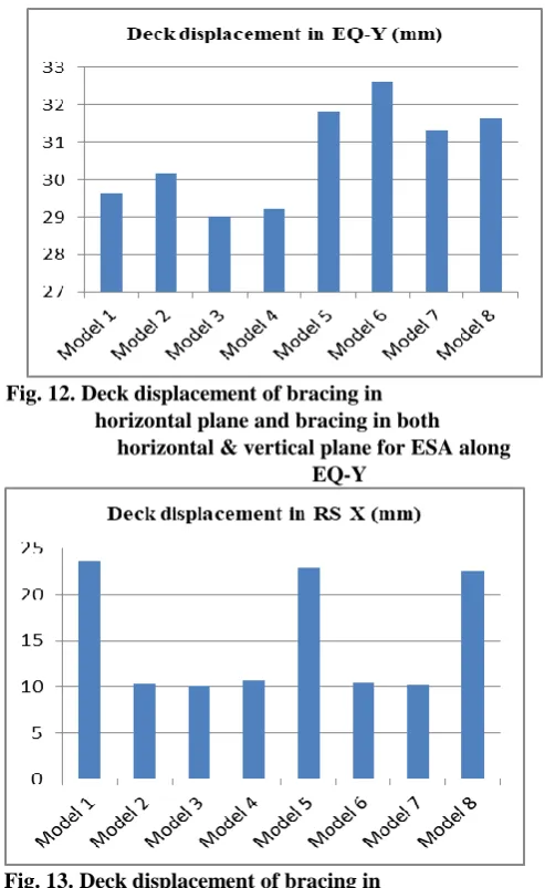
Fig. 12. Deck displacement of bracing in horizontal plane and bracing in both horizontal & vertical plane for ESA along
EQ-Y
Fig. 13. Deck displacement of bracing in horizontal plane & bracing in both horizontal & vertical plane for RSA along EQ-X
[image:5.595.52.294.461.666.2]
Fig. 14. Deck displacement of bracing in horizontal plane and bracing in both horizontal
[image:5.595.302.542.486.669.2]The percentage of reduction in deck displacement (Model 3) for ESA & RSA is 69.47% & 57.28% when compared with X bracing (Model 1), the percentage of reduction for ESA & RSA is 3.81% & 8.15% when compared with V bracing (Model 2), the percentage of reduction for ESA & RSA is 1.98% & 5.34% when compared with K bracing (Model 4), The percentage of reduction in deck displacement with Inverted V bracing (Model 3) for ESA & RSA is 71.50% & 59.63% when compared with X bracing in horizontal & vertical plane (Model 5), percentage of reduction for ESA & RSA is 10.97% & 37.71% when compared with V bracing (Model 6), percentage of reduction for ESA & RSA is 71.31% & 3.08% when compared with Inverted V bracing (Model 7) and percentage of reduction for ESA & RSA is 66.08% & 55.07% when compared with K bracing (Model 8). The reduction in deck displacement shows that Inverted V bracing in the vertical plane (Model 3) is stiffer and less flexible.
C. Base shear:
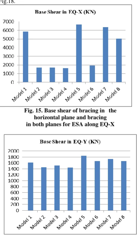
[image:6.595.314.540.49.239.2]The base shear values in X and Y directions resulting from ESA are shown in Fig.15 and Fig.16 respectively. The corresponding results with ESA are shown in Fig.17 and Fig.18.
Fig. 15. Base shear of bracing in the horizontal plane and bracing in both planes for ESA along EQ-X
Fig. 16. Base shear of bracing in horizontal plane and bracing in both horizontal & vertical planes
for ESA along EQ-Y
Fig. 17. Base shear of bracing in horizontal plane and bracing in both horizontal & vertical planes
[image:6.595.306.546.296.465.2]for RSA along RS-X
Fig. 18. Base shear of bracing in horizontal plane and bracing in both horizontal & vertical planes
for RSA along RS-Y
The base shear is least with K bracing in the vertical plane (Model 4) and highest for the (Model 5) with X bracing in horizontal and vertical plane. The percentage of reduction in base shear (Model 4) for ESA & RSA is 72.26% & 64.73% when compared with X bracing (Model 1), the percentage of reduction for ESA & RSA is 3.56% & 64.09% when compared with V bracing (Model 2), the percentage of reduction for ESA & RSA is 4.50% & 7.15% when compared with Inverted V bracing (Model 3).
[image:6.595.49.282.328.728.2]International Journal of Innovative Technology and Exploring Engineering (IJITEE) ISSN: 2278-3075,Volume-8 Issue-12, October 2019
The reduction in base shear shows that K bracing in the vertical plane (Model 4) is very effective in reducing base shear.
VI. CONCLUSIONS
From the results of analytical studies carried out in the current investigation, following conclusions are drawn:
1. The fundamental time period of offshore jacket platform with X bracing is least when compared to other types of vertical plane bracings. The percentage reduction in time period is 5.91% when compared to V bracing, the percentage of reduction when compared to Inverted V bracing is 4.18% and the percentage of reduction is 2.59% when compared to K bracing.
2. The deck displacement of platform with Inverted V bracing is least compared to other types of vertical plane bracings. The percentage reduction in deck displacement is 58.34% when compared to X bracing, the percentage of reduction when compared to V bracing is 8.15% and the percentage of reduction is 5.34% when compared to K bracing.
3. The base shear of platform with K bracing is least compared to other types of vertical plane bracings. The percentage reduction in deck displacement is 64.73% when compared to X bracing, the percentage of reduction when compared to V bracing is 2.81% and the percentage of reduction is 7.15% when compared to Inverted V bracing.
4. The time period is least with Inverted V bracing in horizontal & vertical plane when compared to V bracing in vertical plane, amongst corresponding time period values of all other types of bracing in vertical and horizontal plane. The percentage of reduction when compared to Inverted V bracing in vertical plane is 7.63%. 5. The base shear & deck displacement is least with Inverted V bracing in vertical plane compared to V bracing in horizontal & vertical plane. The percentage of reduction in base shear and deck displacement when compared to bracing in horizontal & vertical plane are 64.95% and 7.08%.
6. The deck displacement, base shear and time period are found to be less for model with bracing in vertical plane only, when compared to models with bracing in both horizontal and vertical planes.
7. The model with Inverted V bracing in vertical plane is found to be optimum model for seismic resistance compared to all other models.
REFERENCES
1. Sreelakshmi M S and Dr. Jayalekshmi R “Seismic Response Control of Offshore Jacket Platform with Friction Damper” International Journal of Scientific & Engineering Research Volume 8, Issue 11, November-2017.
2. Khosro Bargi, S. Reza Hosseini, Mohammad H. Tadayon and Hesam Sharifian “Seismic Response of a Typical Fixed Jacket-Type Offshore Platform under Sea Waves” Open Journal of Marine Science, 2011, 1, 36-42.
3. T. Taghikhany; Sh. Ariana; R. Mohammadzadeh and S. Babaei “The effect of semi-active controller in Sirri jacket seismic vibration control under Kobe earthquake” International Journal for Marine science and Engineering, 3(2), 2013, 77-84.
4. Samira Babaei and Roohollah Amirabadi “Assessment of Semi-Active
Vibration of an Existing Jacket Platform” International Journal of Marine Technology IJMT Vol.6/ summer 2016, 1-10.
5. Shehata E. Abdel Raheem “Nonlinear Analysis of Offshore Structures under Wave Loadings” Journal of Marine Research, 21(1), 2012, 120-124.
6. Harish N and Sukomal Mandal “Analysis of offshore Jacket Platforms” Structural and Engineering Mechanics, 4(2), 2010, 125–138. 7. Muhammad Zubair Muis, Ahmad Yasir Baeda1 and Taufiqur Rachman
“Comparative Study of Structural Geometric to the Ultimate Strength on Fixed Jacket Platform” MATEC Web of Conferences 177, 01007 (2018) 2017.
8. S. Ishwarya and R. Senthil “Inelastic Nonlinear Pushover Analysis of Fixed Jacket-Type Offshore Platform using Different Bracing Systems” Journal of Shipping and Ocean Engineering 6, 2016, 241-254. 9. API-RP2A, “Recommended Practice for planning, Designing and
Constructing Fixed Offshore Platforms”, American Petroleum Institute, Washington D.C., 2002.s
AUTHORS PROFILE
Md. Yousuf Ahmed, PG Student, Department of
Civil Engineering, PDA College of Engineering Kalaburagi Karnataka, India. 585102 Email:
Dr. Aravind Kumar Harwalkar, Associate
Professor, Department of Civil Engineering, PDA College of Engineering Kalaburagi Karnataka, India. 585102 Email: [email protected]