International Journal of Innovative Technology and Exploring Engineering (IJITEE) ISSN: 2278-3075,Volume-8 Issue-3C, January 2019
Abstract: Background/Objectives: Six Sigma methodology is a useful tool for R&D as well as for quality management. We employed Six Sigma methods in development of microlens array for small integrated optical pickup application. Methods/Statistical analysis: The standard DMAIC procedure was employed for carrying out the Six Sigma project. At first, we defined customer needs to plan the project. Secondly, we investigated current level to establish improvement goals. Then, we selected the potential factors affecting the performances of the microlens. We obtained optimum process conditions for the microlens fabrication with design of experiment. Finally, we made management and control plans to maintain the improved results. Findings: A microlens of numerical aperture (NA) 0.85, following the specifications of the Blu-ray disc (BD), was designed, fabricated and evaluated. A novel hybrid lens composed of a refractive lens and a diffractive lens was designed to overcome the difficulties in the fabrication of a high-NA objective lens and to reduce chromatic aberration. The refractive lens was fabricated with glass compression molding technique, and the diffractive lens was fabricated by employing the master molding with electron beam lithography and successive UV embossing process. The refractive lens and the diffractive lens were combined each other on a Si lens holder wafer which was fabricated by photolithography and Si deep reactive ion etching technique. For the evaluation of the optical characteristics of the developed hybrid lens, diffraction efficiency and the wavefront error were measured. The measured average efficiency of the diffractive lens was about 84% and the RMS wavefront error of the hybrid lens was 0.04 rms. Improvements/Applications: The resulting optical performances of the microlens array developed by using the Six Sigma methodology were proved to be sufficient to satisfy the required specifications of optical pickup for BD.
Keywords: Six Sigma, DMAIC, Microlens Array, Refractive Lens, Diffractive Lens
I.INTRODUCTION
Six Sigma methodology is the business process to minimize the waste of resources and maximize the satisfaction of customers by designing and managing usual company activities [1,2]. Six Sigma is the method of approach to introduce various technologies and methods to enterprises for continuous improvement of their core competencies. Since the first introduction of Six Sigma in Motorola in 1987, many companies have adopted the methodology and have been benefited from it in many aspects such as higher productivity, quality improvement and cost reduction for their products and services [3]. Sigma in ‘Six Sigma’ means standard deviation of quality and the quality level corresponding to six sigma
Revised Manuscript Received on January 03, 2019.
Ho-Pyo Hong, Professor, Department of Business Administration,
Gwangju University, Gwangju, Korea
Myung-Bok Lee, Corresponding Author, Professor, Division of
Mechanical and Mold Engineering, Gwangju University, Gwangju, Korea
level means the process where 3.4 defects occur statistically per one million opportunities. The qualities of products or services can be divided into quality of design, quality of production, and quality of use. The quality cost which results from failure of products or services is very significant. The quality cost of design is much more important than the quality cost of production and the quality cost of use, since the poor design quality should result in failure of products finally even if they have been produced precisely according to design specifications. Therefore, applying Six Sigma in R&D stage is very important to reduce the quality cost by preventing wrong design in products. Applying Six Sigma at the R&D stage means accurately understanding customer needs and transforming them into key performance and specifications of the product and deploying it into real product design. This is in agreement with the thought of setting the right goals from the beginning and performing them in the right way.
In this paper, we report the application of the Six Sigma methods in development of microlens array for integrated optical pickup which is the key component for small portable optical disk drive. Microlens array of numerical aperture NA 0.85 was designed, fabricated and evaluated according to the Six Sigma process. We used the DMAIC (define-measure-analyse-improve-control) process for the Six Sigma and described the goals, applied methods and achieved results at each step. By using the process, a fabrication method of a microlens array which can be applied to small optical pickups was established, and the optical performance of the microlens was confirmed by evaluation of optical characteristics.
II.PROPOSEDPROCEDUREANDMETHOD 2.1 Methodology of Six Sigma Process
Several roadmaps can be taken for Six Sigma projects. DMAIC is the general roadmap for Six Sigma which has been successfully employed for quality improvement in product manufacturing and service companies [4-6]. It can also be used in R&D projects as in our case. Table 1 shows the roadmap of the DMAIC project and corresponding goals and major methods employed in each stage of the project.
Development of Microlens for Integrated Optical
Pickup Using Six Sigma Methodology
1
TABLE 1. The DMAIC Roadmap Employed in This Project
Stage Goal Methods
Define
· Define customers and find their needs.
· Select and schedule the project.
· CTQ · VOC
Measure
· Understand present level. · Establish improvement goal.
· MSA · Gauge R&R
Analyse · Select the potential factors. · Draw the vital few X’s.
· Process mapping · C&E matrix
Improve
· Draw the improving plan. · Verify the improvement results.
· DOE · FMEA
Control
· Make management and control plan.
· Standardize the results.
· Control chart · Check list
2.2 Experimental Methods
2.2.1 Optical Design of the Microlens
Code V program was used in optical simulation for the microlens fabrication. A finite conjugate system was employed because it is more preferable than an infinite optical system for the purpose of minimizing number of optical elements. A hybrid lens consisting of a refractive lens and a diffractive lens was designed. The fabrication tolerance of the lens was analyzed using the tolerance analysis function of Code V, and the lens was designed so that fabrication tolerance was sufficiently large.
2.2.2 Fabrication and Evaluation of the Microlens For the fabrication of the refractive lens, an aspheric core was machined and glass raw material was formed by compression molding by using the core. The formed refractive lens was annealed and anti-reflection coated. LAH53 of Ohara, which has a high refractive index and a low dispersion as well as a good formability, was chosen as the glass material of the refractive lens. For the fabrication of the diffractive lens, 3x3 array of diffractive microlens was patterned on a 4” Si wafer by electron beam lithography. Then, the electron beam resist pattern was transferred to a quartz wafer. A diffractive lens master mold with a transparent polymer base film was replicated by UV nanoimprint on the quartz wafer. A lens holder was fabricated by deep reactive ion etching (RIE) of 4” Si wafer to assemble the refractive lens and the diffractive lens. Then, the Si lens holder was eutectically bonded with a pyrex wafer. The diffractive lens master mold was employed to replicate the diffractive lens pattern on the pyrex wafer by UV nanoimprint. Finally, each refractive lens was mounted onto each hole on the lens holder wafer and glued to the holder. For the evaluation of the developed lens unit, diffraction efficiency was measured with a generalized diffraction efficiency measurement method, and the wavefront error of the lens unit was evaluated using a modified Mach–Zehnder interferometer [7].
III.RESULTSANDDISCUSSION 3.1 Stage 1: Define
As shown in Table 1, the goal of this stage is to select and schedule the Six Sigma project. To do this, we should first define our customers and find their needs. Recently, with the advent of the intelligent information society, the necessity of portable ultrahigh-density optical information storage device is rapidly increasing [8]. To implement a small and thin optical pickup for a small-form-factor optical disk drive (SFF ODD) with high density, a small high-NA objective lens is essential. To realize the product, the specification of blu-ray disc (BD), which uses a 405 nm-wavelength laser diode (LD) and an objective lens of NA 0.85, has been targeted. These micro-optical components can be fabricated by employing planar fabrication technologies of semiconductor devices and micro electro-mechanical systems (MEMS). Compared to conventional assembly and adjustment process of various optical elements for optical pickup, this approach of planar process and integrated optics is favorable in view of mass productivity and quality control of micro-optical elements. Therefore, the critical to quality (CTQ) of this project can be said to define and establish the fabrication technology of microlens satisfying the quality of optical pickup for SFF ODD.
3.2 Stage 2: Measure
At this stage, we measure the current technology level through measurement and evaluation, analyze the gap between the performance level requested by the customer and the current level, and establish improvement goals to reach the target. In addition, a measurement system analysis (MSA) is performed to ensure the accuracy of the data used for the phenomena analysis. MSA is the process to evaluate the whole measurement system such as measuring tool, operator, measurement method, measurement environment, in order to obtain reproducibility and repeatability of data [9,10]. It was confirmed that the measurement results are reliable enough through the MSA result of measurement equipments.
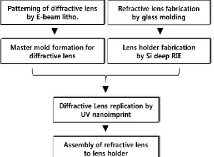
Several differentiating factors should be considered for an optical pickup for SFF ODD using blue LD compared to conventional CD or DVD which use LD of long wavelength. Considering the design issues, we developed a hybrid lens composed of a refractive lens and a diffractive lens. Conventionally, single-element lens with two aspheric surfaces has been employed for high-NA objective lens. In our design, the diffractive lens can be designed to share the burden of an aspheric surface with high refraction power. Therefore, it is possible to use a plano-aspheric refractive lens, which has a lower refraction power than one with two aspheric surfaces. Furthermore, the chromatic aberration can be significantly decreased by using a diffractive lens because Abbe’s numbers of a refractive lens and a diffractive lens have opposite signs [11]. Figure 1 shows the overall process for the fabrication of the hybrid lens. At first, we make a pattern for a diffractive lens designed by optical simulation using electron beam
International Journal of Innovative Technology and Exploring Engineering (IJITEE) ISSN: 2278-3075,Volume-8 Issue-3C, January 2019
then we fabricate a transparent master mold by replicating the diffractive lens pattern. Apart from the mold of diffractive lens, we prepare the refractive lens and a lens holder by glass molding and deep RIE of Si, respectively. Then, we replicate the diffractive lens pattern on the lens holder wafer by UV nanoimprint. Finally, we combine the diffractive lens and the refractive lens by aligning the refractive lens with the imprinted diffractive lens pattern and adhesive bonding the refractive lens to the lens holder.
Fig 1. Fabrication Process for the Hybrid Lens Array.
3.3 Stage 3: Analyse
[image:3.595.57.278.164.326.2]The refractive microlens was fabricated by using glass compression molding technology, and the diffractive microlens was fabricated in a 3x3 two-dimensional array using the electron beam lithography and successive UV nanoimprint process. A lens holder wafer was fabricated by deep RIE of Si to combine the refractive lens and the diffractive lens to each other. We selected the potential factors affecting the fabrication processes of the refractive lens and the diffractive lens as well as the lens holder by process mapping of each fabrication methods. Figure 2 shows the result of process mapping for the fabrication of diffactive lens array and divided each process parameter into controllable and uncontrollable one. The process sequence for the manufacture of the diffractive lens consists of master mold fabrication with electron beam lithography, pattern transfer with RIE, soft polymer mold replication [12,13], UV nanoimprint [14-16], and plasma ashing to remove the residual resin layer.
Fig 2. Process Mapping for the Fabrication of Diffractive Microlens Array (C: Controllable Parameter, U: Uncontrollable Parameter).
We drew the vital few independent variables which influence the optical performances of the microlens by completing the cause-and-effect matrix. Figure 3 shows the cause-and-effect matrix showing the relations between the potential factors and the diffractive lens characteristics in the UV nanoimprint process, which is one of the most important processes for determining the shape and optical performance of the diffractive lens. It can be seen from the figure that the vital few X's which have the high influence on the shape and optical performance of the diffractive lens are the UV exposure time, UV lamp power, and the resin thickness in order of higher importance.
3.4 Stage 4: Improve
To establish the fabrication process conditions of the refractive lens and diffractive lens and assembly methods of the two elements, we carried out the design of experiment (DOE) by selecting the vital few X’s as independent factors. A commercialized software of Minitab was employed for the DOE. The main process parameters and optimized process conditions was found out as a result of the DOE. The
[image:3.595.75.535.347.509.2]complete factorial design using the UV exposure time, UV
power, and the UV-curable resin thickness as 3 factors (X’s) taking 2 levels each was performed. The shape and the optical characteristics of the diffractive lens were selected as the reaction factor (Y). The optimized process parameters in the UV nanoimprint stage were UV exposure time 60 sec, UV lamp power 80 W, and coated thickness of UV-curable resin
1.0 m. According to the process parameters found in DOE,
we implemented the hybrid microlens composed of the refractive lens and the diffractive lens array. Figure 4 shows optical micrographs of a diffraction lens array together with a
magnified view of one diffractive lens and a refractive lens fabricated by an optimization process derived by DOE method, and a schematic diagram of a hybrid lens, which is a combination of a refractive lens and a diffractive lens. In this work, 8-level diffractive lens pattern whose diameter was 746
m, and minimum pitch was 4 m was fabricated by
optimizing the fabrication conditions. The diameter and
height of the refractive lens were 700 m and 500 m,
[image:4.595.101.506.178.369.2]respectively.
Fig 4. Optical Micrographs of (a) Diffraction Lens Array, (b) Magnified View of One Diffractive Lens, and (c) a Refractive Lens Fabricated in This Project, and (d) a Schematic Diagram of a Hybrid Lens, Illustrating the Cross Section of AA’.
We evaluated the optical characteristics of the developed hybrid lens unit. Diffraction efficiency was measured to be 84%, which is above the lower limit of the targeted specification. The wavefront error of the hybrid microlens
evaluated with a modified Mach– Zehnder interferometer
was measured to be 0.04 rms, which is below the upper
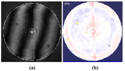
limit of the specification of BD. Figure 5 shows the typical interference fringe pattern and phase map of a hybrid lens unit fabricated in this experiment. The focused spot diameter of irradiated blue light of the hybrid lens unit was 439 nm, which is the value within the specifications. Finally, we summarized the evaluation results of optical performances of the hybrid lens fabricated in this Six Sigma project as a score card in Table 2.
Fig 5. A Typical Interference Fringe Pattern and a Phase Map of Fabricated Hybrid Lens Unit. (a) Interference Fringe, (b) Phase Map.
TABLE 2. The Score Card of the Fabricated Hybrid Lens
Items Unit Spec limit Result
Wave front error rms < 0.045 0.04
Diffraction
efficiency % > 80 84
Spot diameter nm 400 < d < 460 439
3.5 Stage 5: Control
In this stage, we derive measures to control the quality of fabricated microlens and to continuously manage the production line according to the improvement result derived from the previous stage. Control charts are prepared to manage the microlens quality for the main characteristics such as optical properties according to the optimum process conditions. The control chart is a graph showing the trend of data and a control limit line is set to statistically determine the status of the process quality. If the points indicated in the control chart are within the control limit, they are regarded to be in the controlled state. In case these points deviate from the control limit line, the process conditions are checked and managed immediately. Important management points such as key factors of process are also described in check lists and managed strictly in this stage.
IV.CONCLUSION
A microlens of NA 0.85 for SFF optical pickup satisfying the BD specifications was
[image:4.595.55.274.597.721.2]International Journal of Innovative Technology and Exploring Engineering (IJITEE) ISSN: 2278-3075,Volume-8 Issue-3C, January 2019
fabricated and evaluated according to the Six Sigma process. The objective lens unit of the hybrid type composed of a refractive lens and a diffractive lens was designed in order to meet the customers’ needs. The refractive lens was fabricated with glass molding and the diffractive lens was fabricated by master molding with electron beam lithography and successive UV nanoimprint. The process conditions for the fabrication of the hybrid lens were optimized according to the DOE method. As a result of the evaluation of optical characteristics of the hybrid lens, the developed small objective lens was proved to fullfil the required specifications of optical pickup for BD. Therefore, the Six Sigma methodology has been proven to be a very useful tool in the R&D stage as well as in product design and in quality control in mass production line.
ACKNOWLEDGMENT
This study was conducted with research funds from Gwangju University in 2019.
REFERENCES
1. Chowdhury S. Design for Six Sigma: The revolutionary process for achieving extraordinary profits. New Jersey: Prentice Hall; 2002. ISBN 9780793152247.
2. Bertels T. Rath & Strong's Six Sigma Leadership Handbook. New Jersey: John Wiley and Sons; 2003. p. 57-83. ISBN 9780471251248. 3. Antony J, Banuelas R. Key ingredients for the effective implementation
of Six Sigma program. Measuring Business Excellence. 2002 Dec;6(4):20-27. DOI: 10.1108/13683040210451679
4. Hasenkamp T, Olme A. Introducing Design for Six Sigma at SKF. Int J Six Sigma Competitive Advantage. 2008 Apr;4(2):172–189. DOI:10.1504/ IJSSCA.2008.020281
5. Kaushik P, Khanduja D. Application of Six Sigma DMAIC methodology in thermal power plants: A case study. Total Quality Management & Business Excellence. 2009 Feb;20(2):197-207. DOI: 10.1080/14783360802622995
6. Mast JD, Lokkerbol J. An analysis of the Six Sigma DMAIC method from the perspective of problem solving. Int J Production Economics. 2012 Oct;139(2):604-614. DOI: 10.1016/j.ijpe.2012.05.035
7. Lu P, Men L, Sooley K, Chen Q. Tapered fiber Mach-Zehnder interferometer for simultaneous measurement of refractive index and
temperature. Appl Phys Lett. 2009 Apr;94:131110.
DOI:10.1063/1.3115029
8. Luitjens SB, Blum MW, de Boer BM, Fontijn WFJ, van der Aa MAH. Small form factor portable blue drive: power consumption considerations. IEEE Trans Consumer Electron. 2003 Aug;49(3):637-641. DOI: 10.1109/TCE.2003.1233789
9. Douglas C. Introduction to statistical quality control. 7th ed. New Jersey: John Wiley and Sons; 2013. Chap.8. ISBN 9781118146811
10. Wheeler D. EMP III: Evaluating the measurement process & using imperfect data. Knoxville: SPC Press; 2006. ISBN 9780945320678 11. Harm W, Roider C, Jesacher A, Bernet S, Ritsch-Marte M. Dispersion
tuning with a varifocal diffractive-refractive hybrid lens. Opt Express. 2014 Feb;22(5):5260-69. DOI:10.1364/OE.22.005260
12. Plachetka U, Bender M, Fuchs A, Wahlbrink T, Glinsner T, Kurz H. Comparison of multilayer stamp concepts in UV–NIL. Microelectron Eng. 2006 Apr-Sep;83(4-9):944-947. DOI: 10.1016/j.mee.2006.01.041 13. Lee DH, Cho EH, Kim HS, Lee BK, Lee MB, Sohn JS, et al. Multilayer soft mold for UV imprinting the 50 nm pitch dot array. J Vac Sci Technol B. 2008 Mar/Apr;26(2):514-517. DOI: 10.1116/1.2839880 14. Blasi B, Tucher N, Hohn O, Kubler V, Kroyer T, Wellens Ch, et al.
Large area patterning using interference and nanoimprint lithography. Proc SPIE 2016 Apr;9888:98880H. DOI: 10.1117/12.2228458 15. Schleunitz A, Klein JJ, Houbertz R, Vogler M, Gruetzner G. Towards
high precision manufacturing of 3D optical components using UV-curable hybrid polymers. Proc SPIE 2015 Apr;9368:93680E. DOI: 10.1117/12.2076252
16. Kawahara K, Kikuchi T, Natsui S, Suzuki RO. Fabrication of ordered submicrometer-scale convex lens array via nanoimprint lithography