UNIVERSITI TEKNIKAL MALAYSIA MELAKA
The Effects of Cutting Parameter on Workpiece
Surface Layers in the Die Sinking Electrical
Discharge Machine (EDM)
Thesis submitted in accordance with the partial requirements of the Universiti Teknikal Malaysia Melaka for the Bachelor of Manufacturing Engineering
(Manufacturing Process)
By
Mariyam Jameelah Binti Bahari
Faculty of Manufacturing Engineering
UTeM Library (Pind.1/2007)
SULIT
TERHAD
TIDAK TERHAD
(Mengandungi maklumat yang berdarjah keselamatan atau kepentingan Malaysia yang termaktub di dalam AKTA RAHSIA RASMI 1972)
(Mengandungi maklumat TERHAD yang telah ditentukan oleh organisasi/badan di mana penyelidikan dijalankan)
(TANDATANGAN PENULIS)
Alamat Tetap:
322/1 BANDAR BARU SALAK TINGGI, 43900 SEPANG
SELANGOR
Tarikh: 15 MEI 2007
Disahkan oleh:
(TANDATANGAN PENYELIA)
Cop Rasmi:
BORANG PENGESAHAN STATUS TESIS* UNIVERSITI TEKNIKAL MALAYSIA MELAKA
JUDUL:
SESI PENGAJIAN: MEI 2003 – MEI 2007
Saya _____________________________________________________________________
mengaku membenarkan tesis (PSM/Sarjana/Doktor Falsafah) ini disimpan di Perpustakaan Universiti Teknikal Malaysia Melaka (UTeM) dengan syarat-syarat kegunaan seperti berikut:
1. Tesis adalah hak milik Universiti Teknikal Malaysia Melaka.
2. Perpustakaan Universiti Teknikal Malaysia Melaka dibenarkan membuat salinan untuk tujuan pengajian sahaja.
3. Perpustakaan dibenarkan membuat salinan tesis ini sebagai bahan pertukaran antara institusi pengajian tinggi.
4. **Sila tandakan (√)
MARIYAM JAMEELAH BINTI BAHARI
√
DECLARATION
I hereby, declare this thesis entitled “The Effects of Cutting Parameter on Workpiece Surface Layers in the Die Sinking Electrical Discharge Machine (EDM)” is the result of
my own research except as cited in the references.
Signature : ………..
Author’s Name : MARIYAM JAMEELAH BINTI BAHARI
APPROVAL
This thesis submitted to the senate of UTeM and has been accepted as partial fulfilment of the requirements for the degree of Bachelor of Manufacturing
(Manufacturing Process). The members of the supervisory committee are as follow:
……… Main Supervisor
(Official Stamp & Date)
……… Co-supervisor
ABSTRACT
ABSTRAK
DEDICATION
ACKNOWLEDGEMENTS
First and foremost, I would like to express my highest appreciation to my supportive academic supervisor, Mr. Raja Izamshah B. Raja Abdullah for his supervision and support in completing this thesis.
Next, I would like to dedicate my thankfulness to Mr.Hadzley B. Abu Bakar, as my main supervisor for his enthusiastic support and supervision. I would like to acknowledge to (EDM) laboratory technicians, who has been so warmth and kind to provide sincere assistance and good cooperation during the training period. Their co-operation is much appreciated. In addition, I would like to convey thanks to Mr. Akramin B. Mohamad and Mr Sivarao, FKP lecturers, for their assistance, which really spends their time to teach me a lot of knowledge regarding to the DOE.
TABLE OF CONTENTS
Abstract……….……..…i
Abstrak………...ii
Dedication ………....iii
Acknowledgement ………iv
Table of Contents ………..v
List of Figures ………....viii
List of Tables ……….x
Sign and Symbols ……….xi
List of Appendices ………..xii
1.0INTRODUCTION………..1
1.1Statement of the Problem………...2
1.2Objectives………...3
1.3Scope………..3
2.0LITERATURES REVIEW………....4
2.1 Electrical Discharge Machine (EDM)………4
2.2Die-Sinking EDM………...6
2.3Principle of Die sinking EDM………7
2.4 Die Electric Fluid………...8
2.5 Flushing………..9
2.6 Material of Workpiece: ( Mild Steel -AISI 1020 steel )...………...11
2.7 Electrode………...13
2.7.1 Copper Electrode………...13
2.8Surface Texture………15
2.9Surface Roughness (Ra)………...……….16
2.9.2 Surface Effect and Accuracy………..………..21
2.10 Parameter………25
2.10.1 Current………..25
2.10.2 Voltage……….26
2.10.3 Jump Speed………...26
2.11 Overview of DOE………..27
2.11.1 The Role and Implication of DOE………...….28
2.11.2 Orthogonal Array (OA) Experiment………29
2.12 Conclusion of Literature Review.……….…….…31
3.0METHODOLOGY………...33
3.1 Introduction………...33
3.2 Design of Factor (DOE) Methodology……….35
3.2.1 Stage 1: Objective of Experiment………...35
3.2.2 Stage 2: Identification of the Control Factors and Their Levels……...35
3.2.3 Stage 3: Identify Suitable Noise Factor/Response………36
3.2.4 Stage 4: Select the Appropriate Orthogonal Array (OA)………..37
3.2.5 Stage 5: Preparation of the Experiment……….39
3.2.6 Stage 6: Analyzed and Interpret Results of Experiment Trials……...43
3.2.7 Stage 7: Conclusion and Recommendation………...………....44
4.0 RESULTS AND DISCUSSION………...45
4.1 Finding of Surface Roughness………..45
4.1.1 Factorial Design Analysis……….46
4.1.2 Reduced Model……….47
4.1.3 ANOVA Balanced………48
4.1.4 Mathematical Model……….50
5.0 CONCLUSION AND RECOMMENDATIONS………...56
5.1 Conclusion………..………..56
5.2 Recommendations………57
REFERENCES ……….……….58
APPENDICES
A Gantt chart for PSM 1 A Gantt chart for PSM 2 B EDMed set up
LIST OF FIGURES
2.1 Schematic illustration of the electrical-discharge machining process. 5 2.2 A controlled spark discharge removes a very small particle of metal
during each electrical discharge.
5
2.3 Ram-type EDMs plunge a tool, shaped to the form of the cavity required, into a workpiece.
7
2.4a Control spark removes metal during electrical discharge machine. 8
2.4b Erosion process: ball-screw die-sinker. 8
2.5a Down through the electrode. 10
2.5b Up through the workpiece. 10
2.6a By vacuum flow. 11
2.6b By vibration. 11
2.7 Standard terminology and symbol to describe surface finish (Quantity is given in µin).
15
2.8 The Arimethic mean value. 17
2.9 Coordinate used for surface roughness measurement. 18
2.10 Standard lay symbols for engineering surface. 19
2.11 Comparison of surface roughness produced by common production process.
20
2.12 Heat-affected zones in EDM. 21
2.13 Effect of pulse length on surface roughness and wear. 23 2.14 Typical SEM micrographs of the recast layer on the cross-section. 23 2.15 SEM photomicrograph of the recast layer of the tool steel after EDM at
5 A.
24
2.16 Thickness of the recast layer at various EDM conditions. 24
3.2 The 3 steps in designing Orthogonal Array. 37
3.3 Experiment layout preparation. 39
3.4a (a)Copper electrode (b) Mild steel AISI 1020. 40
3.4b Mild steel AISI1020. 40
3.5a Vertical position for electrode. 41
3.5b The tool and the workpiece were submerged in a dielectric fluid. 41
3.6 EDM die sinking Sodick LN2/LQ Series. 41
3.7a Portable Surface Roughness Tester (SJ 301) 42
3.7b The Scanning Electron Microscope (SEM) 42
4.1 Normal Probability Plot of the Effects 46
4.2 Mean Effects Plot (data means) for Ra 46
4.3 Pareto Chart of the Effects standardized (First model) 47
4.4 Pareto Chart of the effects (Second model) 47
4.5 Cube Plot (data means) for Ra 48
4.6 Data of an ANOVA: Ra versus IP 49
4.7 Estimated Coefficient for Ra 50
4.8 Exp. 1; Ra = 2.52µm 52
4.9 Exp. 2; Ra = 8.36µm 52
4.10 Exp. 3; Ra = 2.68µm 52
4.11 Exp. 4; Ra = 7.49µm 52
4.12 Exp. 5; Ra = 3.81µm 52
4.13 Exp. 6; Ra = 5.64µm 52
4.14 Exp. 7; Ra = 3.04µm 53
LIST OF TABLES
2.1 AISI 1020 Steel Composition 12
2.2 Mechanical Properties 13
2.3 Thermal Properties 13
2.4 The Physical Properties of Copper Electrode 15
2.5 Orthogonal Array Designation 30
3.1 The Level of Process Parameter for Copper Electrode 36
3.2 The Setting of EDM Parameters 36
3.3 Orthogonal Array Table 38
3.4 Orthogonal Array Table for Experiment 38
4.1 Data of surface Roughness (Ra) Test 45
4.2 Analysis of Variance for Ra 49
LIST OF ABBREVIATIONS, SYMBOLS, SPECIALIZED
NOMENCLATURE
% - percent
°C - Celsius
µ - micro
µin - micro inch
A - Ampere
ANOVA - analysis of variance cm - centimeter
CNC - computer numerical control
DC - direct current
DOE - design of experiment EDM - electrical discharge machine EWR - electrode wear rate
in - inch
kHz - kilohertz kPa - kilopascal
m - meter
mm - millimeter MPa - mega Pascal
MRR - material removal rate OA - orthogonal Array Ra - arithmetic mean value Rq - root mean square average SEM - scanning electron microscope
V - Volt
LIST OF APPENDIX
A Gantt chart for PSM 1 A Gantt chart for PSM 2 B EDMed set up
CHAPTER 1
INTRODUCTION
1.0 Introduction
Electric discharge machining provides an effective manufacturing technique that enables the production of parts made of special materials with complicated geometry which is difficult to produce by conventional machining processes. Controlling the process parameters to achieve the required dimensional accuracy and finish placed this machining operation in a prominent position.
Electrical Discharge Machine (EDM) is a non traditional manufacturing process based on removing material from a part by means of a series of repeated electrical discharges between tool, called the electrode, and the part being machined in the presence of a dielectric fluid. (Luis et al. 2005)
They are virtually zero forces between the tool and the workpiece, so that very delicate work can be done. The process leaves no burrs on the edges. Its use has expanded very rapidly and now it is widely used to produce large body-forming dies in the automotive industry. (DeGarmo et al. 1997)
The process doesn’t involve mechanical energy, the hardness; strength and toughness of the workpiece material do not necessarily influences the removal rate. The frequency of discharge or the energy per discharge is usually varied to control the removal rate, as are the voltage and current. The removal rate and surface roughness increase with increasing current density and decreasing frequency of spark.
The most important machining performance of EDM are the removal rate, the electrode wear, accuracy and surface texture. In this paper the effect of cutting parameters on workpiece surface layers in the die sinking electrical discharge machine is discussed.
1.1 Statement of the Problem
Modern EDM machinery is capable of machining geometrically complex or hard material component, that are precise and difficult to machine such as heat treated tool steels, composites, super alloy, ceramic, etc. Surface finish produce on machined surface plays an important role in production. It becomes more desirable so as to produce a better surface when hardened materials are machined, requiring no subsequent polishing.
1.2 Objectives
The purposes of this project are:
i. To evaluate the quality of the surface layer produce by different EDM parameters.
ii. To find the significant machining parameter that influences the surface roughness using orthogonal array approach.
iii. To characterize the morphology of EDMed surface of different machining parameters
1.3 Scope
According to the objective, the selected scopes for this project are:
i. To understand the EDM die sinking machining process.
ii. To obtain the surface finish by EDM die sinking with copper electrode.
iii. Study the effects of surface layer on the workpiece by using Scanning Electron Microscope (SEM)
iv. Apply the design of experiment (DOE) and ANOVA approach to analyze the most significant factor that influences the machining performance.
CHAPTER 2
LITERATURE REVIEW
2.1 Electrical Discharge Machine (EDM)
Electrical discharge machining (EDM) is one of the most extensively used non conventional material removal processes. Its unique feature of using thermal energy to machine electrically conductive parts regardless of hardness has been its distinctive advantage in the manufacture of mould, die, automotive, aerospace and surgical components.
EDM does not make direct contact between the electrode and the workpiece eliminating mechanical stresses, chatter and vibration problems during machining. The basis of EDM can be traced as far back as 1770, when English chemist Joseph Priestly discovered the erosive effect of electrical discharges or sparks. (Newman et al. 2003)
However, it was only in 1943 at the Moscow University where Lazarenko exploited the destructive properties of electrical discharges for constructive use. They developed a controlled process of machining difficult-to-machine metals by vapourising material from the surface of metal. The Lazarenko EDM system used resistance–capacitance type of power supply, which was widely used at the EDM machine in the 1950s and later served as the model for successive development in EDM. (Newman et al. 2003)
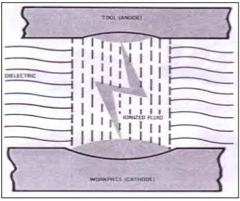
nonconducting) fluid (Figure 2.1) .When the potential difference between the tool
and the workpiece is sufficiently high, a transient spark discharge thorough the fluid, removing a very small amount of metal from the workpiece surface (Figure 2.2).
[image:21.595.190.454.229.397.2]The capacitor discharge is repeated at rates of between 50kHz and 500 kHz, with voltages usually ranging between 50V and 380V and current from 0.1 A to 500 A (Serope et al. 2001).
Figure 2.1: Schematic illustration of the electrical-discharge machining Process. (Serope et al. 2001)
[image:21.595.218.391.483.628.2]2.2 Die-Sinking EDM
Die sinker or sinker EDM a common name for vertical EDM. Taken from the antiquated cavity- making process called hobbing. Hobbing is the process of forcing a pre hardened tool steel shape or hob into the workpiece material under great pressure, effectively cold-forming a cavity for a die or mold. This process was called sinking, a die or die sinking, so the term “sinker” for EDM evolved naturally because an electrode was sunk into the workpiece instead of a hardened hob (Bud et al.
1997).
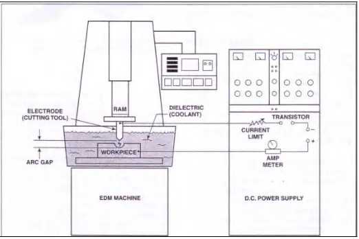
RAM EDMing machines are also referred to as die sinkers or vertical EDMs and range in sizes and automation from manual operating table top systems to large CNC ones. A ram EDM a number of main subsystems:
i. Power supply ii. Dielectric fluid iii. Electrode iv. Servo system
The power supply provides series of DC current Electric discharges between the electrode and the work piece. It also controls:
i. Pulse voltage ii. Current
iii. Pulse frequency iv. Electrode polarity
The die sinking EDM, Figure 2.3 has a cutting tool (electrode) shaped to the
Figure 2.3: Ram-type EDMs plunge a tool, shaped to the form of the cavity required, into a workpiece (Courtesy of Kelmar Associates).
2.3 Principle of Die sinking EDM
According to Krar, the principle of spark erosion was just followed. The workpiece and the tool (electrode) are placed in a working position in such a way that they do not touch each other. The cutting process takes place in a tank where the tool and work are separated by gap that is filled with an insulating fluid.
The workpiece and the tool are both connected to a DC power supply with a cable. When the switch on one cable lead is closed, an electrical potential is applied between the tool and work. Initially, no current flow because the dielectric fluid between the tool and work is an insulator.
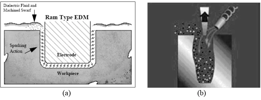
As soon as the gap between them is reduced, a spark jumps across the gap and highly heats a very small area of the work material. The current is then automatically shut off and the discharge channel collapses very quickly. The molten metal on the surface of the material evaporates explosively, forming a small crater (Krar et al. 1998). Figure 2.4(a) shows the control spark removes metal during
(a) (b)
Figure 2.4: (a) Control spark removes metal during electrical discharge machine (by Technical Service Department-Brush Wellman Inc.); (b) Erosion process: ball-screw
die-sinker (Zhao et al. 2003)
The metal particles are washed away by the dielectric fluid and the process is repeated many times per second. As one discharge follows another, the crater continues to get bigger, taking the shape of the electrode.
Figure 2.4 (b) shows the die-sinking process of the conventional ball-screw
driven EDM, in which the electrode moves up and down slowly along with auxiliary flushing required for removal of debris. When machining very deep and narrow features such as a hole, the slow movement of the electrode does not efficiently expel the eroded debris from the electrode/workpiece interface. (Zhao et al. 2003)
2.4 Die Electric Fluid