@
adoptee, ine.
ACB-5500
ACB-5500 User's Manual
51/4"
Winchester Disk Controller
SCSI to ST506
October, 1985
Additional copies of this manual, or other Adaptec literature, may be obtained from:
Adaptec, Inc.
Literature Department 580 Cottonwood Drive
Milpitas, CA 95035
The information in this document is subject to change without notice.
No part of this document may be copied or reproduced in any form or by any means without prior written consent of Adaptec, Inc.
Adaptec, Inc., 580 Cottonwood Drive, Milpitas, California 95035
Copyright 1984
1.0
2.0
3.0
TABLE OF CONTENTS
INTRODUCTION • • • • • • • • • • • 1-1
1.1 Scope • • • • • • • • • • •
·
.
.
• 1-11.2 Reference Documents • •
·
. .
.
.
.
.
.
• • 1-1• 1-1
1.3 ACB-5580 Features
1.4
1.5
Block Layout
.
.
.
Product Specification •
1.5.1 Physical Dimentions
· . .
.
.
.
1.5.2 Power Requirements • • • • • • • •
1.5.3 Environmental Requirements • • • •
• 1-3
• • 1-4
• • 1-4
• 1-4
• 1-4
1.6 Quality Assurance • • • • • • • • • • • 1-4
THEORY OF OPERATION • • •
2.1 System Configuration
.
.
. .
INSTALLATION •
3.1 Unpacking
.
.
.
.
.
.
. .
.
.
2-1 • 2-3• • • 3-1
• 3-1
3.2 Preparation of Installation Area • • • • • . • 3-1
3.3 Installation • • • • • • • • • • • • • • • 3-2
3.4 Configuring the ACB-5500 • • • • • • • • • 3-3
3.5
3.6
3.7
3.4.1 SCSI Reser Option.. • • • • • 3-4
3.4.2 Hard-Sectored/Removable Drives • • • • 3-4
3.4.3
3.4.4
Diagnostic Mode • •
Parity Enable •
3.4.5 SCSI Bus Address
Powering-on the ACB-5500
· .
.
. . .
.
.
· .
. .
.
. .
.
.
• • 3-4
• 3-5
• • 3-5
• 3-5
Communicating with the ACB-5500 •
Formatting with the ACB-5500
.
.
. .
• 3-64.0 SCSI INTERFACE DESCRIPTION • • • •
·
. .
• • 4-1 • 4-1 4.1500504-00
General Description of SCSI •
·
. . · .
.
4.1.1
4.1.2
4.1.3
Bus Signals
. .
.
.
.
.
. .
· . .
• • • 4-2 4.1.1.14.1.1.2
4.1.1.3
Busy (BSY)
.
.
.
.
·
.
.
• 4-2Select (SEL)
Control/Data (C/O)
·
.
.
• • 4-2
4-2
4.1.1.4 Input/Output (I/O) • • • • 4-2
Message (MSG)
Request (REQ)
• • 4-2
• 4-2 4.1.1.5
4.1.1.6
4.1.1.7
4.1.1.8
4.1.1.9
Acknowledge (ACK)
Attention (ATTN)
·
. . . · .
.
4-2Reset (RST) •
· .
.
.
.
.
.
• 4-3
4-3
4.1.1.10 Data Bus (DB: 7-0, Parity) 4-3
Bus Phases
.
. .
·
·
.
·
· ·
·
·
· ·
4-34.1.2.1 Bus Free Phase
·
· · ·
4-44.1.2.2 Arbitration Phase
· ·
· ·
·
4-44.1.2.3 Selection Phase
·
·
·
·
4-44.1.2.4 Rese1ection Phase
·
4-54.1.2.5 Information Transfer Phases
· ·
4-54.1.2.5.1 Command Phase
· · ·
4-74.1.2.5.2 Data Phases
·
·
4-74.1.2.5.3 Status Phase
·
· ·
·
4-74.1.2.5.4 Message Phases
·
·
·
4-74.1.2.6 Signa 1 Restrictions Between
Phases
·
· . · ·
· ·
•·
·
4-8Bus Conditions
.
·
·
•·
·
· · ·
·
· ·
·
4-84.2 4.1.4 4.1.5 4.1.6 4.1.3.1 4.1.3.2
~ttention Condition • • • • 4-8
Reset Condition
· .
.
.
·
.
4-8Phase Sequencing • •
Timing • • • • • •
Electrical Interface
. . . . . 4-9
• • • • • • •. • • 4 -10
·
.
.
.
.
• 4-104.1.7 Connection Diagram • • • • •
Message Specification • • • • •
4.2.1 Message System • • • • • • •
·
. .
. · .
4-11· .
.
.
.
• 4-12· .
.
.
.
• 4-124.2.2 SCSI Message Descriptions • • • • •
4.2.2.1 Single Byte Messages
..
.
4-13 • 4-134.3 Functional Description of SCSI Commands • • • 4-16
4.3.1 Single Command Example • • • • • • • • • 4-16
4.4
4.5
4.3.2
4.3.3
4.3.4
Disconnect/Reconnect Example
Linked Command Example •
Command Queuing Example. •
·
.
4-17
4-17
·
. .
• 4-17Command Structure
.
.
.
. . . .
.
.
.
• 4-184-18 4.4.1 4.4.2 4.4.3 4.4.4 4.4.5 4.4.6 4.4.7 4.4.8 4.4.9
Command Descriptor Block (CDB) • • •
Group Code • • • • • • • • • • • 4-19
Operation Code • •
Logical Unit Number
· .
• • 4-19Command Specific Bits
Relative Address B i t .
Logical Block Address
Number of Blocks •
Control Byte • • •
• 4-19
.
. .
.
. .
• 4-20.
.
.
.
.
. .
.
• 4-20 4-20·
. .
• 4-20• • • • 4-20
5.0
6.0
ST 506 INTERFACE DESCRIPTION •
·
. .
• 5-15.1 Introduction
.
.
.
. .
.
.
. . .
• • • 5-15.2 Interface Signals •
·
.
.
• 5-15.2.1 Optional Lines for Hard-Sectored
and Removable Drives • • • • • • 5-6
5.3 Disk Format • • •
. .
. .
. . .
.
·
. . .
5-6COMMAND DESCRIPTIONS •
.
.
.
. .
. .
• • 6-16.1
6.2
Test Unit Ready (00 H)
.
.
.
.
.
.
.
.
.
• • • • 6-3Rezero Unit (0lH) • . • • • • • •
·
.
.
.
.
• 6-46.3 Request Sense (03H) • • • • • • 6-5
6.3.1 Bad Format on Drive
. . .
.
.
. .
.
6-96.4 Format Unit (04H) • • • • • • • • •
· . .
• 6-106.4.1
6.4.2
Defect Handling • • •
.
.
.
• 6-126-14 Format Unit Data •
6.5 Read (08 H) ••
· .
.
.
. .
6.6
6.7
Write
Seek
·
. .
.
• • • • 6~18
·
.
.
6-206.8 Translate (0F H)
. .
.
• • • 6-22
• • 6-23
.
.
.
6.9 Set Threshold (10 H)
· .
.
.
.
.
6.10 Read/Reset Usage Counter (1l H). •
6.11 Inquiry (12 H) ••
. .
.
.
.
.
.
6.12 Write Data Buffer (13H)
·
.
. .
6.13 Read Data Buffer (14 H) ••
6.14 Mode Select (ISH)
6.15 Reserve (16 H)
.
.
• • 6-25 • 6-26 • 6-28·
. . .
.
• 6-29 • 6-30·
. . .
.
• 6-31·
.
.
·
. .
6-35 6.16 Release (17 H) • ••6.17 Mode Sense (1A H) ••
·
.
. . .
.
.
.
.
• 6-40.
.
. . .
.
• 6-416.18 Start/Stop Un it (lB H) • •
6.19 Receive Diagnostic (1C H).
6.2~ Send Diagnostic (1DH ) • •
6.2~.1 Diagnostic 6~ 6.2~.2 Diagnostic 61
6.2~.3 Diagnostic 62
.
6.2~.4 Diagnostic 63
6.2~.5 Diagnostic 64
6.20.6 Diagnostic 65
6.20.7 Diagnostic 66
6.21 Read Capacity ( 25H)
.
6.22 Read (28H>
.
.
.
.
.
.
6.23 Write (Extended (2A)6.24 Write and Verify (2E H)
6.25 Verify (2F H) ••
.
6.26 Search Data Equal (31H>
6.27 Set Limits (33 H) • • • • • Appendix A, Diagnostic Mode Self-Test
·
.
. . .
.
. .
.
• • 6-42· .
.
.
. .
.
.
• 6-43 • • • • • • 6-44.
.
.
.
· ·
·
· .
.
.
6-46·
·
· ·
· ·
6-46·
·
·
·
·
·
· ·
·
· ·
6-46·
· ·
•· ·
6-46· ·
·
· ·
·
6-46·
·
·
·
·
·
·
·
6-47·
•· ·
·
• 6-47·
·
·
·
·
6-5~· · ·
·
· ·
•·
·
· ·
6-52·
.
.
6-53·
.
.
.
· .
· .
6-54·
. .
.
· .
• • 6-55
· .
.
• 6-566-6~
Fig. 1-1 2-1 2-2 2-3 4-1 4-2 4-3
LIST OF FIGURES
Title
ACB-5500 Board Layout
·
.
.
.
.
. .
.
Page
• • 1-3
ACB-5500 Block Diagram
.
.
.
.
.
ACB-5500 Microcode Structure
Typical SCSI Configurations
. .
.
. .
.
. . .
• •Host Adapter Bus Termination • • • • •
SCSI Bus Pin Assignments • • • • • • • • • •
Group 0 Commands (6-Byte Commands) • • • •
• • 2-2
·
.
.
2-3 2-4• 4-11
• • • • 4-12
4-18
4-4 Group 1 Commands (10-Byte Extended Block Address • • 4-19
4-5 5-1 5-2 6-1 6-2 6-3 6-4 6-5 6-6 6-7
Completion Status Byte • • • • • • •
ACB-5500 Cabling • • • • • • • • • •
· .
• • • • 4-21ST 506 Control Signal Driver/Receiver Circuit
TEST UNIT READY Command • • • • • • • • • • •
REZERO UNIT Command • • • • • • • • • • •
REQUEST SENSE Command
REQUEST SENSE Data • •
.
.
.
. .
·
.
. .
.
.
.
.
FORMAT UNIT Command
. .
. .
.
.
. .
.
. .
Sector Level Defect Skipping
.
.
.
· .
.
Sector Spacing within Cylinders
·
.
.
.
·
.
.
5-2
• • • 5-5
· .
.
6-3 • • • 6.;..4• • 6-5
• • • 6-5
• • • 6-10
·
.
.
6-12· . .
6-136-8 Sector Spar i ng and Over flow Sector s • • • • • • 6-14
6-9' Format Unit Data Block (Drive Formatting) • • • 6-15
6-10 Format Unit Data Block (Cylinder Level Formatting) • 6-17
6-11 READ Command • •
·
.
. .
.
.
. .
.
. .
.
.
.
6-12 WRITE Command
.
.
.
.
. .
.
.
.
.
• • 6-18
6-20
6-13 SEEK Command • •
·
.
.
·
.
. .
.
.
·
.
. .
• 6-226-14 TRANSLATE Command
.
.
·
. . .
• 6-236-15 TRANSLATE Data • • • • • • • 6-24
6-16
6-17
6-18
6-19
6-20
SET THRESHOLD Command
·
. . .
.
.
.
. · . . .
• 6-25READ/RESET USAGE COUNTER Command •
·
.
• • • 6-26READ/RESET USAGE COUNTER Parameters
. .
.
.
• • 6-27INQUIRY Command
·
.
. .
.
.
.
.
. .
.
• • 6-28INQUIRY Parameters
.
.
.
.
• • • 6-286-21 WRITE DATA BUFFER Command
· .
.
.
.
.
.
. .
.
.
6-296-22 READ DATA BUFFER Command • 6-30
6-23 MODE SELECT Command
.
. .
• 6-316-24 Extent Descriptor List • • 6-32
6-25 Drive Parameter List for Soft-Sectored, Fixed Drives 6-33
6-26 Drive Parameter List for Hard-Sectored, Removable
Drives • • • • • • • • 6-34
6-27 RESERVE Command
· . .
.
. . .
.
.
.
. . .
.
• • 6-356-28 Extent Descriptor Format • • • 6-38
6-29 RELEASE Command
.
.
.
. . .
.
• • 6-406-30 MODE SENSE Command •
.
. .
. .
.
• • • • • • 6-416-31 START/STOP UNIT Command
.
.
.
.
.
.
.
.
.
• • • 6-426-43
6-32 RECEIVE DIAGNOSTIC Command •
6-33 RECEIVE DIAGNOSTIC Data 6-44
6-34 SEND DIAGNOSTIC Command .0 .
·
.
.
6-446-36
6-37
6-38
6-39
6-40
6-41
6-42
READ CAPACITY Command
READ CAPACITY Parameters
READ Command
. . .
•. .
·
WRITE Command
.
.
.
•WRITE and VERIFY Command
·
VERIFY Command •
.
.
.
.
SEARCH DATA EQUAL Command
· ·
·
·
•·
·
·
·
·
· ·
·
6-5~•
·
. .
•.
.
•.
. .
.
.
6-51· . ·
•·
· ·
•·
•·
·
·
6-52·
·
·
·
· · · ·
·
•·
· ·
6-53·
·
·
·
·
·
·
•·
6-54·
.
.
.
• • • 6-55·
.
.
.
.
• • 6-566-43 SEARCH DATA EQUAL Argument • • • • • • • • • • • • • 6-58
6-44 SET LIMITS Command • • • • • 6-6~
Table
3-1
3-2
4-1
4-2
5-1
5-2
5-3
5-4
6-1
6-2
6-3
6-4
6-5
6-6
A-I
LIST OF TABLES
Title
Configuration Jumpers
Interleaved Sectors/Track
· .
. .
. .
.
.
.
.
.
.
.
. .
.
.
.
Page
• • 3-4
• • 3-9
Information Transfer Phases
·
.
.
.
. .
• • • • 4-6Message Codes Supported by the ACB-5500
. .
Jl Connector Pin Assignment • •
·
.
.
.
. .
.
.
.
J2, J3, J4, and J5 Connector Pin Assignment.ACB-5500 Soft-Sectored Disk Format
ACB-5500 Hard-Sectored Disk Format • •
·
.
.
.
Command Code Summary
. . .
.
· · .
·
.
·
Class 00 Error Codes in Sense Byte (Drive Errors)
• • 4-13
• • 5-3
• 5-4
• 5-7
• 5-8
.6-1/6-2
·
6-6Class 01 Error Codes in Sense Byte (Target Errors)
·
6-7Class 02 Error Codes (System-Related Errors)
Format Options
. .
.
. .
.
.
SEARCH DATA EQUAL Argument •
Self Test Error States • •
·
· .
·
.
·
•.
· .
·
·
6-8 6-116-59
1.0 INTRODUCTION
The ACB-5500 disk controller provides an intelligent interface from an ANSI X3T9.2 SCSI host interface to four ST506 compatible disk drives.
1.1 SCOPE
This manual contains all of the information necessary to quickly install and operate the ACB-5500 with an SCSI compatible Host Adapter and up to four ST506 disk drives.
1.2 REFERENCE DOCUMENTS
o ANSI X3T9.2 Small Computer System Interface Specification
1.3 ACB-5500 FEATURES
o The ACB-5500 supports four ST506 hard- and soft-sectored drives.
o The ACB-5500 supports a fully arbitrating SCSI system with up to seven other controllers or hosts sharing the SCSI bus.
o The ACB-5500 provides maximum SCSI bus throughput by supporting bus disconnection and reconnection for explicit and implied seeks.
o The ACB-5500 offers complete device independence by auto configuring to any size formatted drive. By storing drive parameters on the drive at format time, the need for host initialization of the controller for various drive types is eliminated.
o The ACB-5500 may handle defects on a sector level by allowing the host to request that spare sectors be reserved on a cylinder basis. This provides formatted disks with constant data capacity and allows cylinder level formatting.
o The ACB-5500, utilizing a 2K dual-ported buffer, eliminates the need for sector interleaving. This allows the host to read a track of data in a single revolution.
o The ACB-5500 reduces selection overhead by allowing the host
to link commands. Once a command is completed, the
con-troller will immediately request and execute the next linked command.
o The ACB-5500 reduces system overhead by queuing commands to
the controller from different hosts. As commands are
com-pleted, the next queued command will be executed.
o The ACB-5500 provides great operating system flexibility by
offering sector lengths of 256, 512, or 1024 bytes. The
sector length is programmed at format time.
o The ACB-5500 supports direct and relative addressing of
logical blocks.
o The ACB-5500 guarantees excellent data integrity by utilizing
a 32-bit error correction code on both the data and 1.0.
fields, SCSI bus parity checking and generation, and data buffer parity checking.
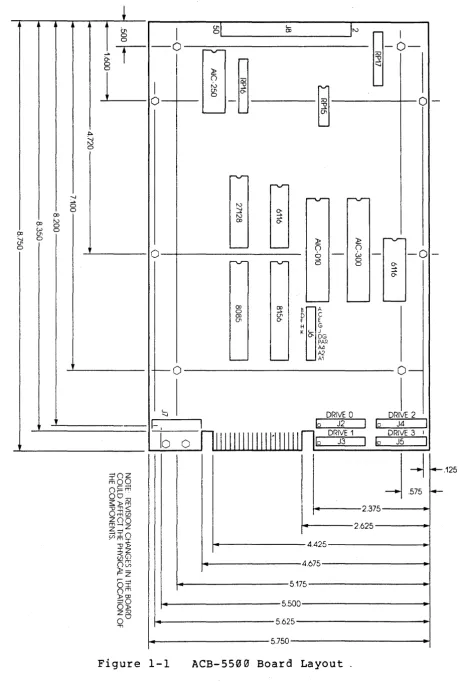
1.4 BLOCK LAYOUT
The component layout of the ACB-5500 is shown in Figure 1-1.
+
.
(;,
I
g;\c- I~
CXl
~-b-0 0
~r
- 0 1'0'"'0
-~
0 ~
L
0I
N~
(}1
0
0
0
' -::. '.J ~ 0
rv-'-J
rvr v
-i:J ~
0 '-J
~
CP N
CP N 0 CP
0-t.:> 0 CP (}1
1'0'"'
'.J 0 ~ ;t::
(}1
0 ' - - - ' - - - 0 0
- 0
0 6 - i..J
-
-rv- rv- 0 0
0 ~
0-~
----
' -CXl ex>B~A
0 U;
D C
CXl
(}1 0- F E H G K c- J
0- DG PAR
A4 f:.2
0 . . . - 0 . . . - A1
- 0
0
-
<-DRIVE 0 DRIVE 2
'-J
1- .
I 10 J2 I b J4 I10
II I I I I I II I I I 1'1 I I I I IDRIVE 1 DRIVE 3 I
0 110 J3
I
10 J5I
j:
f4---iOZ
ffioo
ocrTi r ..
-00;;v $»m O:g~ me/) ZOO m----iz Z----i (/jIO
. m I 4.425
-0» IZ
U50
.125
Om
4.675~z
r~
OI 5175
om »CP
~o 5.500
0» z;;v
0° 5.625
"T'\
[image:16.615.70.530.77.761.2]1.5 PRODUCT SPECIFICATION
1.5.1 PHYSICAL DIMENSIONS
Length: Width: Height:
1.5.2
1.5.3
8.76 inches 5.75 inches
.8 inches
POWER REQUIREMENTS
Voltage (volts)
+5
+12
Tolerance (Units)
4.75 to 5.25
+10.8 to +13
Current (max amps)
1.5
0.300
ENVIRONMENTAL REQUIREMENTS
Operating
Temperature (F/C): 32/0 to 131/55
10% to 95% Humidity:
Ripple (volts, RMS)
.150
.150
Storage
-40/-40 to 167/75 10% to 95%
Altitude (ft.): Sea Level to 10,000 Sea Level to 20,000
Exhaust air flow may be required to keep the air on both sides of the board at or below the maximum operating temperature if ade-quate convective ventilation is not available.
1.6 QUALITY ASSURANCE
The ACB-5500 has been processed through Adaptec's extensive
quality control procedure. All Adaptec custom ICs have been
fully tested at temperature and voltage margins. All boards have
been fabricated and assembled under close quality inspection. All boards have passed complete incircuit test procedures, have endured burn-in testing, and have been fully functionally tested. Adaptec should be notified immediately of any deviations from our high standard of quality.
2.9 THEORY OF OPERATION
The ACB-5500 provides a powerful mechanism for connecting up to
four ST506 compatible disk drives to a host computer via the
Small Computer Systems Interface (SCSI). The SCSI provides a
powerful general purpose device-independent connection usable by a wide range of computing systems.
The ACB-550~ provides all of the data separation circuitry
required to convert 5 Mb/sec NRZ to MFM encoded data. Adaptec's
AIC-250 encode/decode chip designed with a discrete VCO circuit control write precompensation, addresses mark detect and data separation functions.
The ACB-5500 provides all required formatting and data
synchronizing functions for ST506 compatible disk drives. The
formatting function, data serializing/deserializing and ECC checking are provided by Adaptec's proprietary sequencer chip, the AIC-010.
The ACB-5500 provides up to 2K bytes of dual-ported buffering to allow high performance data access even if the attached host
system can only accept data at very low rates. Adaptec's AIC-300
buffer controller provides full dual porting for the buffer memory.
The data transfer path is fully checked, using ECC and buffer
parity checking to assure data integrity. Data integrity is not
compromised by the unchecked control microprocessor.
All low-speed control operations are managed by a powerful 8-bit microprocessor executing instructions from a 16K read-only
con-trol memory. The large control memory allows the implementation
of several optional functions as well as a diagnostic self-tst capability.
The formatting process stores device dependent parameter
informa-tion on the attached disk drives. When the ACB-5500 is powered
up, i t automatically configures all internal tables from the stored parameters so that no drive configuration commands are required from the host system.
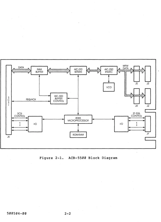
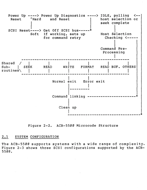
Figure 2-1 shows the ACB-5500 block diagram, and Figure 2-2
S AIC-300 BUFFER
C REQ/ACK CONTROL
S
I J4 J2
SCSI ST-506
CONTROL CONTROL
I/O I/O
J1
J6
Figure 2-1. ACB-5500 Block Diagram
[image:19.618.34.562.39.765.2]Power Up ----> Power Up Diagnostics ----> Reset AHard and Reset
I
SCSI Reset----> Get Off SCSI bus---* Soft If working, sets up
for command retry
I
I
I
Shared /
I
Sub-I
SEEK routines\I
READ WRITE FORMAT
I
I
I
I
IDLE, polling
<--host selection or seek completeI .
Host Selectlon Checking
<---I
Command Pre-Processing
I
I
I
READ BUF. OTHERS
I
I
I .
Normal eXIt Error exit
I
Command linking ---*
I
Clean upI
---*
Figure 2-2. ACB-5500 Microcode Structure
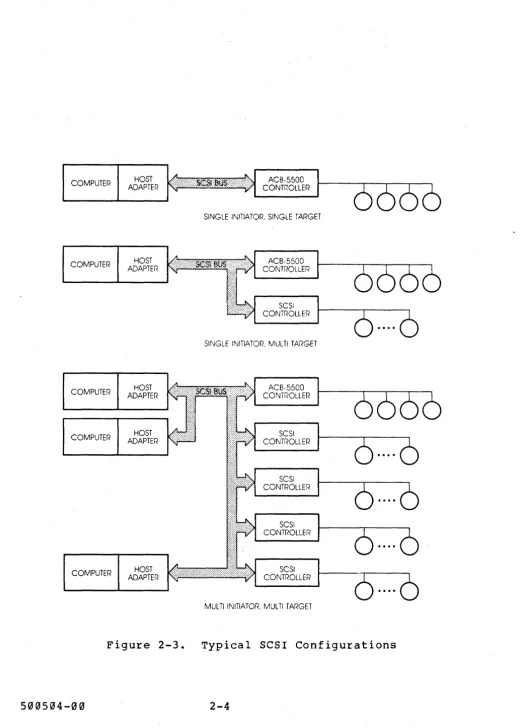
2.1 SYSTEM CONFIGURATION
[image:20.612.54.536.114.736.2]COMPUTER
COMPUTER
COMPUTER
COMPUTER
COMPUTER
HOST ADAPTER
HOST ADAPTER
HOST ADAPTER
HOST ADAPTER
HOST ADAPTER
Figure 2-3.
500504-00
ACB-5500 CONTROLLER
SINGLE INITIATOR, SINGLE TARGET
ACB·5500 CONTROLLER
SCSI CONTROLLER
SINGLE INITIATOR, MULTI TARGET
ACB-5500 CONTROLLER
SCSI CONTROLLER
SCSI CONTROLLER
SCSI CONTROLLER
SCSI CONTROLLER
MULTI INITIATOR. MULTI TARGET
(5· ..
·6
Typical SCSI Configurations
[image:21.617.40.564.38.767.2]3.9 INSTALLATION
The ACB-5500 is a self-contained circuit board. All logical and
electronic functions required for its normal operation are
contained on the circuit board. The ACB-5500 is simple to
install, operate, and maintain.
3.1 UNPACKING
The ACB-5500 is shipped in a protective carton with shock absorbing material and static protecting material completely
surrounding the card. The carton should be examined for external
damage as it is opened. The cards were physically inspected when
packed. Any mechanical damage to the cards should be reported to
the shipper and to Adaptec as soon as possible.
CAUTION
All circuit boards containing VLSI circuitry have some
sensitivity to electro-static discharge. The ACB-5500 is no
exception. Proper handling precautions, including personnel
grounding and work surface grounding, should be taken to prevent circuit stress which can cause premature circuit failure.
3.2 PREPARATION OF INSTALLATION AREA
The ACB-5500 is generally designed into the host system or the
peripheral disk system. Proper attention should be given to the
location of ACB-5500 so that the necessary ventilation, installa-tion clearances, and cabling paths are provided.
The power output is low enough so that convective ventilation will be sufficient if the air and surrounding surfaces are at a
temperature of 55 degrees Centigrade or less. If this
requir'ement cannot be met by the system enclosure in its worst case environment, then the system enclosure must provide for appropriate ventilation and cooling.
Care should be taken to support the card mechanically. Any
appropriate combination of the 8 mounting holes provided can be used, depending on the forces to which the system will be
sub-jected. No conductive material should come in contact with the
Installation clearances, both for the ACB-5500 and the selected power and signal cabling configuration, should be sufficient to optimize system cost, manufacturability, and maintainability.
The ACB-5500 emits a small amount of radio-frequency signals. Extremely sensitive components, such as high band-width analog
sensors, should be properly shielded from the ACB-5500. Normal
cas e con st r u c t ion i s s u f f i c i en t to s hie I d the A CB - 55 00 as
required by the FCC. If FCC compliance is required and the SCSI
leaves the box in which the ACB-5500 is installed, the high frequency signals generated by normal SCSI operation may require connector and cable shielding.
The ACB-5500 and all other partially shielded electronic devices are sensitive to high power high frequency electrical or magnetic
sources. The ACB-5500 should be protected from such sources
while it is operating. In particular, unshielded switching power
supplies should be physically isolated from all electronic boards
and their interconnecting cables. External noise sources, such
as welding machines and radio transmitters, should be similarly
isolated from electronic systems. Cable and connector shielding
may be required in some environments.
An appropriate power source must be provided. Care should be
taken to prevent ground loops and other power disturbances.
Proper programming support must be provided to generate the
required command sequences. Additional program support must be
provided to manage the SCSI protocols. Any system supporting the
ACB-4000 will also support the ACB-5500. Use of the advanced
performance oriented functions will require a more powerful SCSI host adapter that supports disconnect/reconnect, command linking,
and arbitration. Use of the advanced command functions requires
expanded software support. Adaptec's host adapters will provide
the required SCSI protocol services, but must receive the
com-mands to be executed from appropriate system software. Many
other SCSI systems are also available.
3.3 INSTALLATION
The following steps are required for installation of the ACB-5500
into a system properly designed to accept it. These steps are
separate from any other testing and installation procedures required by other portions of the system, but can often be done in conjunction with those other installation steps.
1) Inspect ACB-5500 for obvious physical damage before
installing.
2) Install proper jumpers (see Section 3.4) to enable the
desired ACB-5500 functions and to define the address of the ACB-5500 on the SCSI Bus.
3) Install ACB-5500 with appropriate mounting hardware.
4) Make the required cable connections to the ACB-5500. The cable connections are:
J7 - Power cable
J8 - SCSI cable
J2, J3, J4, JS - ST506 data cable (radial connections
as required) Jl - ST506 control cable.
5) Install ST506 drives according to the manufacturer's
direc-tions. The drives must have appropriate drive select address
and bus terminators set. The last ST506 drive on the control
cable daisy chain must be terminated.
5) Power on the system and perform any power-on test procedures
required by the system.
7) Format the attached drives. (See Section 3.7.)
Note: In a production environment, the drives may be
option-ally formatted by a dedicated ACB-5500 manufacturing work
station before installation. Since all parameters are stored
on the drive by the formatting procedure, further formatting or parameter specification is not required after
installa-t i on. The ACB- 5500 will auto conf igure to the dr i ve
param-eters at power-on time.
8) Perform appropriate system test and verification procedures.
Errors related to drive operation, ACB-5500 operation, SCSI operation, and certain installation errors will be indicated through the normal SCSI error presentation mechanism.
3.4 CONFIGURING THE ACB-5500
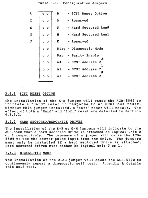
The ACB-5500 has a number of options that must be selected by the installation of hardware jumpers located at position J6 on the
controller. The function of each jumper pair is shown in Table
3-1. The jumper header is designed to accommodate jumpers with
Table 3-1. Configuration Jumpers
A o 0 B - SCSI Reset Option
C 0 0 D - Reserved
E 0 0 F - Hard Sectored Lun~
G o 0 H - Hard Sectored Luni
J 0 0 K - Reserved
o 0 Diag - Diagnostic Mode
o 0 Par
-
Parity Enable2
o 0 A4 - SCSI Address 2
1
o 0 A2 - SCSI Address 2
0
0 0 Al - SCSI Address 2
3.4.1 SCSI RESET OPTION
The installation of the A-B jumper will cause the ACB-5500 to initiate a "Hard" reset in response to an SCSI bus reset. without this jumper installed, a "Soft" reset will result. The effect of both a "Hard" and "Soft" reset are detailed in Section
4.1.3.2.
3.4.2 HARD SECTORED/REMOVABLE DRIVES
The installation of the E-F or G-H jumpers will indicate to the ACB-5500 that a hard sectored drive is attached as logical Unit 0
or 1 respectively. The presence of a jumper will cause the
ACB-5500 to use the sector pulse input from the drive. The jumpers
must only be installed if a hard sectored drive is attached. Hard sectored drives must either be logical unit 0 or 1.
3.4.3 DIAGNOSTIC MODE
The installation of the DIAG jumper will cause the ACB-5500 to
continuously repeat a diagnostic self test. Appendix A details
this self test.
[image:25.620.43.562.43.733.2]3.4.4 PARITY ENABLE
The installation of the PAR jumper will cause the ACB-5500 to c he c k for bus 0 u t (d a t a i n t o t h e A C B - 5500) par i t y err 0 r s • Th i s
jumper should only be installed if all SCSI devices communicating
with the ACB-5500 generate SCSI data parity. The ACB-5500 will
always generate parity on bus in data.
3.4.5 SCSI BUS ADDRESS
The installation of jumper A4, A2, and Al set the SCSI bus
address for the ACB-5500. SCSI devices can have an address of 0
to 7 but no two devices can have the same address.
3.5 POWERING-ON THE ACB-5500
Once the ACB-5500 is properly configured, the controller may be
powered on. When power is supplied to the system, the controller
will enter a power-up mode and wait for a maximum of 18 seconds
for the drive to become ready. During the l8-second power-on
sequence, the controller performs a self test and begins checking
for drive 0, 1, 2, and 3 to become ready. If the host sends a
command requiring access to a drive before i t has become ready
(and before 18 seconds have elapsed) the controller will accept
the command and cont i nue to check for a ready s ta tus. Once the
drive comes ready, the controller will then execute the command;
if 18 seconds elapse, and the drive does not come ready, a DRIVE
NOT READY (04H) error will result. The controller will then
check for a ready status on the next command requiring access to that drive.
Once a drive comes ready, the controller will recalibrate the
head to track 0. If the drive started at track 0, the controller
will step the head off of track 0 to confirm that the drive can
seek and that the track 0 signal was valid. With the drive's
ability to seek confirmed, the controller then seeks back to t r a c k 0. Th e d r i ve act u a tor (i f i t can be see n) a pp ear s tom a k e
a short 'bl ip. '
The controller then attempts to read from track 0, parameter
information, which is written during formatting. If the drive is
unformatted, or had been formatted by other than an Adaptec c on t roll e r , the par am e t e r i n for mat ion i s not pre sen t • Th e
controller then sets "blown format" to warn the user that the
drive is unusable, the reset sequence is stopped and the
controller is ready for a command. The drive must be formatted
to allow a READ or WRITE access to disk data.
If the drive is correctly formatted, the controller will seek the drive to the last cylinder and read the largest block address
present. The parameter information and largest block addresses
Once the last block address has been read, the controller will seek the drive back to track 0, stopping several- times in 'zones' to read the devect counyt within each zone. This defect count is also saved in the controller to asllow i t to better predict the
location of a block on the disk for accurate seeking.
Once a drive is formatted, the host can determine the drive size
(READ CAPACITY, 258 , command) and self-configure without any
driver software modlfication. This device independence provides
a major advantage for host systems using true SCSI controllers over the SASI-like units that send parameters at a reset and with commands.
3.6 COMMUNICATING WITH THE AC8-5500
The SCSI bus is a simple bus to interface. However, a quick
reading of the SCSI spec may leave you lost due to its extreme
attention to detail. Also, some SASI-like controllers exist on
the market which allow some deviation from the ANSI/SCSI
protocol. The important point to remember in designing a drive
routine is that once the controller is started by the host, THE
CONTROLLER CONTROLS THE SCSI BUS. The controller drives the data
direction line (I/O), the phase lines (C/O and MSG) and initiates
data transfers (REQ). The host drive should make no assumptions
about the bus phases or byte counts. In addition, the controllr
can (and wi 11) change phases betwen operations whi Ie going
through intermediate phases. Thus, the phase lines (C/O and MSG)
are only valid when the controller asserts REQ. Do not write
your driver or allow your hardware to follow phases when REQ is not active or i t may be 'fooled'- by phase changes between REQ. Also, other controllers only support some 6-byte commands, thus some users have set up counters in their software to send a
6-byte command. Since the ACB-5500 controller supports 6 and
10-byte commands, the hardware/software should not count out the command bytes but rather should send command bytes as long as the
controller requests them. Trust the controller; i t 'knows' how
many bytes it needs.
The sequence of operations for a single command used in the simplest of SCSI applications would be:
1) Select the controller onto the bus (wake i t up). Be sure
select remains asserted until the controller responds Busy.
2) Send the ACB-5500 the appropriate command bytes until i t
changes phases (do not count bytes). If too many or too few
bytes are REQuested, check for valid command op code and proper SCSI REQ/ACK timing.
3) If required, send/receive data until phase changes (do not
count bytes; controller will determine data direction).
4) Receive (REQ/ACK cycle) 1 status byte and save for evaluation
(See Section 4.5).
5) Receive (REQ!ACK cycle) 1 message byte (See Section 4.2).
6) Check status byte. If Busy bit set, resend command; if
Check bit set, send REQUEST SENSE (03 H) command to get error. 3.7
---
FORMATTING WITH THE ACB-5500----
---A sample MODE SELECT command for a Seagate ST412-type drive is described below:
Step 1: MODE SELECT Command
Drive Type: Seagate ST412: 306 cylinders 4 heads
28 uS step rate
Reduced write current at cylinder 256 write precompensation at cylinder 256
Hex Description
MODE SELECT Command
15 OP Code (ISH) for MODE SELECT
00 Formatting Lun0
00 Reserved
00 Reserved
16 Number of data bytes appended (16H)
00 Reserved
Extent Descriptor List
00 Reserved
00 Reserved
08 Length of drive descriptor list
00 Density code
00 Reserved
00 Reserved
00 Reserved
00 High byte of block size to be formatted (256 bytes)
01 Middle byte of block size to be formatted
00 Low byte of block size to be formatted
01 01 02 32 04 01 00 01 00 00 01
Drive Parameter List
Interface code (must be 01) High byte of cylinder count
Hard sector drive or removable cartridge Low byte of cylinder count
Total number of heads
Note: Two additional bytes would be added for a hard-sectored or removable drive (See Section 6.14).
After the MODE SELECT has been transferred to the controller and good completion status has been sent to the host, the drive may be formatted.
Step 2: FORMAT UNIT
Interleave of 1:1
Fill data fields with E5H
1 defect at head 2, cylinder 11, 256 bytes from index 2 space sectors per cylinder
Hex
04 IE
E5 00 01 00
FORMAT UNIT command
Description
Op code (04 H for FORMAT UNIT command)
Lun0 and indicate fill character and defect descriptor appended
Character to be filled in data fields High byte of interleave (must be 00) Low byte of interleave
Reserved
FORMAT UNIT Data Block
00 Format entire unit
02 Allocate 2 spare sectors per cylinder
00 High byte of length of defect list
08 Low byte of length of defect list
00 High byte of cylinder number of defect
00 Middle byte of cylinder number of defect
0B Low byte of cylinder number of defect
02 Head number of defect
00 High byte of defect bytes from index
00 Middle byte of defect bytes from index
01 Middle byte of defect bytes from index
00 Low byte of defect bytes from index
The same procedure can be used for formatting single cylinders. Section 6.4.2 contains details on changes required to the FORMAT UNIT command for cylinder level formatting.
The ACB-5500 allows you to select the desired interleave factor
with the FORMAT UNIT command. The interleave can range from zero
to the number of blocks per track, minus 1. The number
represents the number of physical blocks between consecutive logical block numbers, thus an interleave of 1 means that the sectors are consecutive.
The use of an interleave factor 1 allows a maximum transfer rate but will only be effective with a host adapter and system capable
of very high transfer rates. On the other hand, the use of
interleaving can maximize the storage capacity of your drive.
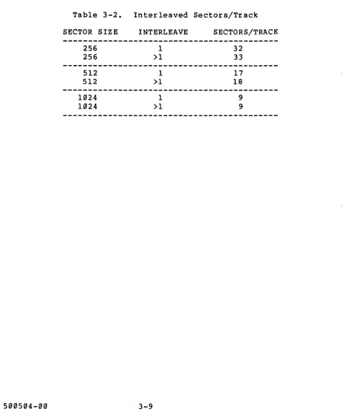
Table 3-2 shows the number of formatted sectors per track for different block sizes and interleaves when using soft sectored drives.
Table 3-2. Interleaved Sectors/Track
SECTOR SIZE
256 256
512 512
1024 1024
INTERLEAVE
1
>1
1
>1
1
>1
SECTORS/TRACK
32 33
17
18
9
[image:30.615.57.570.164.758.2]4.9 SCSI INTERFACE DESCRIPTION
This section briefly describes the SCSI protocol implemented by
the Adaptec ACB-5500 controller. The SCSI protocols are
described in detail in the ANSI X3T9.2 Small Computer System Interface Specification, version 14.
4.1 GENERAL DESCRIPTION OF SCSI
This system interface provides an efficient method of
communica-tion between a maximum of 8 computers and peripheral I/O devices.
The eight-port daisy-chained bus defined by the SCSI specifica-tion supports the following features:
o Single or multiple host system
o Multiple peripheral devices and device types
o Multiple overlap of peripheral device operations
o Bus contention resolution through arbitration on a prioritized
basis
o Asynchronous data transfer at up to 1.5 MBytes/sec.
o Host-to-host communication.
Communication on the bus is allowed between two bus ports at a
time. A maximum of eight (8) bus ports are allowed. Each port
is attached to a n SCSI device (e.g., controller or host adapter) •
. When two devices communicate with each other on the bus, one acts
as an Initiator and the other acts as a Target. The Target
(typically a controller) executes the operation. A device will
usually have a fixed role as an Initiator or Target, but some
devices may be able to assume either role. The ACB-5500 always
assumes a Target role.
An Initiator, or attached host adapter, may address up to four
logical units on an ACB-5500. Each logical unit is a separate ST
506 disk drive having the characteristics (i.e., capacity) with
which it was formatted. The ACB-5500 manages them as independent
Access to the SCSI bus is handled through arbitration. The arbitrating SCSI device with the highest bus address is given
priority. The Initiator selects a Target. The Target then
manages all further communications, requesting commands from the Initiator, transferring the required data, and transmitting
ending status. A Target may reselect an Initiator to complete a
disconnected operation.
Data transfers on the bus are asynchronous and follow adef i ned
REQUEST/ACKNOWLEDGE protocol. One eight-bit byte of information
may be transferred with each handshake.
4.1.1 BUS SIGNALS
The SCSI bus consists of 9 control signals and 9 data signals.
These are described below:
4.1.1.1 BUSY (BSY)
BSY is an "or-tied" signal which indicates that the bus is in use.
4.1.1.2 SELECT (SEL)
SEL is an "or-tied" signal used by an Initiator to select a Target or by a Target to reselect an Initiator.
4.1.1.3 CONTROL/DATA (C/O)
C/D is a Target-driven signal to indicate whether CONTROL or DATA
information is on the data bus. Assertion indicates CONTROL.
Outbound control information is a command while inbound control information is status.
4.1.1.4 INPUT/OUTPUT (I/O)
I/O is a Target-driven signal which controls the direction of data movement on the data bus relative to an Initiator.
A~sertion indicates INPUT to the Initiator.
4.1.1.5 MESSAGE (MSG)
MSG is a Target-driven signal indicating the MESSAGE phase.
4.1.1.6 REQUEST (REQ)
REQ is a Target-driven signal indicating a request for a REQ/ACK data transfer handshake.
4.1.1.7 ACKNOWLEDGE (ACK)
ACK is an Initiator-driven signal, in response to a target REQ,
indicating the transfer of a byte to or from the ACB-5500
4.1.1.8 ATTENTION (ATTN)
ATTN is an Initiator-driven signal indicating the ATTENTION condi-tion. ATTN is a request from the Initiator to transmit a message to the ACB-5500.
4.1.1.9 RESET (RST)
RST is an "or-tied" signal indicating the RESET condition. The
ACB-55~~ never initiates a RESET condition.
4.1.1.1~ DATA BUS (DB: 7-~, PARITY)
Eight data bit signals, plus a parity bit signal, comprise the DATA BUS. DB(7) is the most significant bit and has the highest priority during arbitration. Significance and priority decrease with decreasing bit number with the least significant being DB (") •
Each of the eight data signals DB(7) through DB(0) is uniquely assigned as a Target or Initiator bus address (i.e., DEVICE
1.0.). The Device ID is set in an ACB-5500 by jumpers AI, A2,
and A4.
Data parity, DB(P), is odd. The ACB-5500 always generates correct bus parity for inbound transfers. A jumper is installed to enable the ACB-5500 to check outbound parity for those systems that support parity. All Initiators must support parity if the ACB-5500 parity check is enabled.
4.1.2 BUS PHASES
The bus has eight distinct operational phases and cannot be in more than one phase s imul taneously. Deta i led phase informati on and timing specifications are contained in the ANSI X3T9.2 SCSI Specification.
0 BUS FREE 0 ARBITRATION 0 SELECTION 0 RESELECTION
0 COMMAND \
0 DATA
INFORMATION TRANSFER PHASES
0 STATUS
4.1.2.1 BUS FREE PHASE
The BUS FREE phase, indicating that the bus is available for use, is entered by the deassertion and passive release of all bus signals. Once the BUS FREE phase is detected, the active initia-tor must deassert and passively release all bus signals (within a BUS CLEAR DELAY) after deassertion of BSY.
Devices sense BUS FREE when SEL and BSY are not asserted (simultaneously within a DESKEW DELAY of 45 nsec) and the RESET condition is not active.
4.1.2.2 ARBITRATION PHASE
The ARBITRATION phase allows one SCSI device to gain control of the bus. Once a device that wants to arbitrate for the bus detects the BUS FREE phase, i t waits a BUS FREE DELAY, 800 nsec, and then asserts BSY with its own 1.0. bit on the Data Bus. (Data parity is not guaranteed valid during ARBITRATION.)
After an ARBITRATION DELAY, the device examines the data bus. If a higher priority 1.0. is on the bus or a select from another device is present, the device clears itself from arbitration by releasing the BSY and 1.0. signals. If the device determines that its own 1.0. is the highest priority, it leaves BSY asserted and asserts SELECT. ARBITRATION is then complete.
4.1.2.3 SELECTION PHASE
During the SELECTION phase, the I/O signal is deasserted so that this phase can be distinguished from the RESELECTION phase. The ACB-5500 operates in both arbitrating and non-arbitrating sys-tems. In non-arbitrating systems, there may be only one Initia-tor. It may raise select with the Target 1.0. asserted whenever the BUS FREE Phase is p~esent.
In arbitrating systems, the SELECTION phase is entered with both BSY and SEL asserted; the Initiator then waits a minimum of a Bus C I ear 0 e 1 a y p 1 usa Bus Set tIe 0 e 1 a y be for e d r i v i n g the- D A T A bus with the Target 1.0. and its own 1.0. After two DESKEW DELAYS, the Initiator then releases BSY. If only one Initiator is installed, and no disconnection is supported, the Initiator need not provide its own 1.0.
On detecting the condition that Select and its own 1.0. are asserted, and BSY and I/O are not asserted, the selected Target examines the DATA bus for the Initiator 1.0. and responds by asserting BSY.
After a minimum of two DESKEW DELAYS, 90 nsec., (following the
detection of BSY from the Target), the Initiator deasserts SEL
and may change the DATA signals.
The Initiator may "time out" the SELECTION phase by deasserting
the I.D. bits on the bus. If, after a TIMEOUT DELAY, 250 msec,
BSY has not been asserted, one of the selection timeout proce-dures specified in the ANSI X379.2 SCSI specification will be followed. The ACB-5500 drives BSY within 250 microseconds of
detecting SEL and its own 1.0. If parity checking is enabled,
Bus Out parity must be valid during the selection phase.
4.1.2.4 RESELECTION PHASE
If an Initiator supports reconnection, the ACB-5500 can release the SCSI bus for other activities while the disk devices are
performing mechanical motions. The Initiator informs the
ACB-5500 that it can support reconnection by transmitting the proper bits in the Identify MESSAGE OUT right after the Selection phase. The ACB-5500 will then disconnect at the proper times, first presenting a Save Pointers message and a Disconnect message to
the Initiator. The Save Pointers message indicates to the
Initiator that i t must preserve all necessary information to later continue the operation when reconnect takes place.
After successfully gaining control of the SCSI by winning
arbi-tration, the Target has both BSY and SEL asserted. It then
informs the Initiator that i t desires reconnection by asserting
the I/O signal. The ACB-5500 then drops BSY. The reselected
Initiator then asserts BSY. When the ACB-5500 sees the
Initia-tor's BSY, i t raises BSY and drops SEL, causing the Initiator to drop BSY, ending in the same state as i t would be for a normal
selection. The ACB-5500 then informs the Initiator which device
is being reconnected with an Identify MESSAGE IN. The Initiator then restores all the necessary state information to continue the or i gin a lope rat ion •
. 4.1.2.5 INFORMATION TRANSFER PHASES
The COMMAND, DATA, STATUS and MESSAGE phases are all used to
transfer data or control information through the SCSI bus.
The C/D, I/O and MSG signals are used to differentiate the
various INFORMATION TRANSFER phases. Note that these signals are
Table 4-1. Information Transfer Phases
--I SIGNAL I
MSG
I
C/DI
I/O3 0 0
3 0 1
0 1 0
3 1 1
1 0 0
1 3 1
1 1 0
1 1 1
NOTES: 3
1
INIT ACB-5533
PHASE NAME
DATA OUT DATA IN COMMAND STATUS
Reserved Reserved
MSG OUT MSG IN
--_
..= SIGNAL DEASSERTION
= SIGNAL ASSERTION
= INITIATOR
= TARGET
DIRECTION OF INFORMATION XFER
(INIT to ACB-5533) (ACB-5533 to INIT) (INIT to ACB-5533) (ACB-5530 to INIT)
(INIT to ACB-5533) (ACB-5533 to INIT)
The INFORMATION TRANSFER phases use the REQ/ACK handshake to control data transfer. Each REQ/ACK allows the transfer of one byte of data. The handshake starts with the Target asserting the REQ signal. The Initiator responds by asserting the ACK signal, indicating a byte transfer. The Target th~n deasserts the REQ signal and the Initiator responds by deasserting the ACK signal.
with I/O signal asserted, data will be input to the Initiator from the ACB-5530. The ACB-5500 ensures that valid data is available on the bus (at the Initiator port) before the assertion of R E Qat the In i t i at 0 r po r t. Th e d a t a r em a ins val i dun t i l the
assertion of ACK by the Initiator. The Initiator must ensure that data has been read from the bus before asserting ACK. The ACB-5530 compensates for cable skew and the skew of its own drivers. The ACB-5533 always guarantees good parity on inbound data transfers.
With the I/O signal not asserted, data will be output from the Initiator to the ACB-5533. The Initiator must ensure valid data on the bus (at the Target port) before the assertion of ACK on the bus. The Initiator should compensate for cable skew and skew of its own drivers. Valid data must remain on the bus until the ACB-5530 deasserts REQ. The ACB-5503 will optionally check parity on the outbound data transfers.
[image:37.613.65.556.44.340.2]During each INFORMATION TRANSFER phase, the BSY line remains asserted, the SEL line remains deasserted, and the ACB-5500 will
continuously envelop the REQ/ACK handshake(s) with the C/O, I/O
and MSG signals in such a manner that these control signals are valid for at least a BUS SETTLE DELAY before the REQ of the first handshake and remain valid until the deassertion of ACK at the end of the last handshake.
4.1.2.5.1 COMMAND PHASE
The COMMAND phase is used by the ACB-5500 to obtain Command Descriptor Blocks from the Initiator.
The ACB-5500 asserts the C/O signal and deasserts the I/O and MSG signals during the REQ/ACK handshake(s) of this phase.
4.1.2.5.2 DATA PHASES (DATA IN/DATA OUT)
The DATA phase includes both the DATA IN phase and DATA OUT phase.
The DATA IN phase is used by the ACB-5500 to input device data or
state information to the Initiator. The ACB-5500 asserts the I/O
signal and deasserts the C/O and MSG signals during the REQ/ACK handshake(s) of this phase.
The DATA OUT phase is used by the ACB-5500 to obtain write data
and control parameters from the Initiator. The ACB-5500
deasserts the C/O, I/O and MSG signals during the REQ/ACK hand-shake(s) of this phase.
4.1.2.5.3 STA!I'US PHASE
The STATUS phase is used by the ACB-5500 to send status
informa-tion to the Initiator. Controller status contains information
relating to the completion of the last command executed. Section
4.5 details the status information implemented in the ACB-5500.
The Target asserts C/O and I/O and i t deasserts the MSG signal during the REQ/ACK handshake(s) of this phase.
4.1.2.5.4 MESSAGE PHASES (MESSAGE IN/MESSAGE OUT)
The MESSAGE phase includes both MESSAGE IN and MESSAGE OUT
phases. Section 4.2.2 details the messages information
imple-mented in the ACB-5500.
The MESSAGE IN phase is used by the ACB-5500 to present a
message to the Initiator. The ACB-5500 asserts C/O, I/O and MSG
The MESSAGE OUT phase is used by the ACB-550~ to obtain a message from the Initiator. The ACB-5500 invokes this phase only in response to the ATTENTION condition from the Initiator. In response to the ATTENTION condition, the ACB-5500 asserts C/O and MSG and deasserts the I/O signal during the REQ/ACK handshake(s) of this phase. The Target handshakes byte(s) in this phase until
the ATTN signal goes false.
4.1.2.6 SIGNAL RESTRICTIONS BETWEEN PHASES
When the BUS is between phases, the following restrictions apply to the bus signals:
o The BSY, SEL, REQ and ACK signals may not change.
o The C/O, I/O, MSG and DATA signals may change.
o The ATTN and RST signals may change as defined under the descriptions for the ATTENTION and RESET conditions.
4.1.3 BUS CONDITIONS
The bus has two asynchronous conditions: The ATTENTION condition and the RESET condition. These conditions cause certain BUS DEVICE actions and can alter the bus phase sequence.
4.1.3.1 ATTENTION CONDITION
ATTENTION allows the Initiator to signal the ACB-55~0 of a wait-ing message. The ACB-55~0 may access the message by invoking a MESSAGE OUT phase.
The Initiator creates the ATTENTION condition by asserting ATTN at any time except during the ARBITRATION and BUS FREE phase.
The ACB-55~~ responds when ready with the MESSAGE OUT phase. The Initiator keeps ATTN asserted if more than one byte is to be transferred.
The Initiator can only deassert the ATTN signal during the RESET condition, during a BUS FREE phase, or while the REQ signal is asserted and before the ACK signal is asserted during the last REQ/ACK handshake of a MESSAGE OUT phase.
While the ATTN is asserted, the Initiator must continue to respond to the Target command or data transfers since the Target may not process the ATTN immediately.
4.1.3.2 RESET CONDITION
The RESET condition, created by the assertion of RST, is used to immediately clear all devices from the bus and to reset these devices and their associated equipment.
RESET can occur at any time and takes precedence over all other
phases and conditions. Any device (whether active or not) can
invoke the RESET condition. On RESET, all devices immediately
(within a BUS CLEAR DELAY, 800 nsec) deassert and passively
release all bus signals except RST itself.
The RESET condition stays on for at least one RESET HOLD TIME, 25
usee. During the RESET condition, no bus signal except RST can
be assumed valid.
Regardless of the prior bus phase, the bus resets to a BUS FREE
phase following a RESET condition.
By setting jumpers A-B on the ACB-5500 jumper header (J6), the user can select either a hard reset mode or a soft reset mode.
When the jumper is installed, a hard reset mode is established. When in hard reset mode, a RESET condition will force the ACB-5500 to clear all uncompleted commands, to release all reserva-tions including dual port reservareserva-tions, and to return all other modes, including mode select, set limits, and diagnostic states
to their power on default conditions. The next time a drive is
selected from the Initiator, the drive and all its mode select parameters will be re-initialized.
When the jumper is not installed at position A-B, a soft reset
mode is established. After clearing the SCSI bus information and
waiting until. the Reset Condition has ended, the ACB-5500 will attempt to complete any uncompleted commands which were fully
identified. All SCSI device reservations and operating modes are
preserved. The ANSI X3T9.2 SCSI specification defines the
condi-tions under which commands are considered completely identified and completed.
4.1.4 PHASE SEQUENCING
Phases are used on the bus in a prescribed sequence. In all
systems, the RESET condition can interrupt any phase and is
always followed by the BUS FREE phase. (Any other phase can also
be followed by the BUS FREE phase.)
The normal progression is from BUS FREE to ARBITRATION, from ARBITRATION to SELECTION or RESELECTION and from SELECTION or RESELECTION to one or more of the INFORMATION TRANSFER phases